
Specifications


Table Of Contents
- Product description
- External component identification
- Illustrated parts catalog
- Removal and replacement procedures
- Preliminary replacement requirements
- Component replacement procedures
- Service tag
- Computer feet
- Battery
- Switch cover and keyboard
- Memory module
- Optical drive
- Speakers
- WWAN module
- Palm rest
- Hard drive
- WLAN module
- Display assembly on computers with 15-in displays
- Top cover
- Power button board
- RTC battery
- Display assembly on computers with 14-in displays
- Bluetooth module
- Modem module
- USB connector assembly
- Heat sink and fan
- Processor
- System board
- SIM
- Computer Setup
- Specifications
- Computer specifications
- 14.1-in WXGA display specifications
- 15.6-in WXGA display specifications
- Hard drive specifications
- DVD-ROM Drive specifications
- DVD±RW Double-Layer Combo Drive specifications
- Blu-ray Disc ROM Drive with SuperMulti DVD±R/RW Double-Layer specifications
- System DMA specifications, Windows Vista and XP
- System interrupt specifications, Windows Vista
- System interrupt specifications, Windows XP
- System I/O address specifications, Windows Vista
- System I/O address specifications, Windows XP
- System memory map specifications, Windows Vista
- System memory map specifications, Windows XP
- Screw listing
- Torx T8M2.5×6.0 screw
- Torx T8M2.5×4.0 screw
- Phillips PM2.0×2.0 screw
- Phillips PM2.0×3.0 screw
- Phillips PM2.0×3.0 screw
- Phillips PM2.5×6.0 screw
- Phillips PM2.5×11.0 captive screw
- Phillips PM3.0×4.0 screw
- Phillips PM2.0×4.0 screw
- Phillips PM2.5×3.0 screw
- Phillips PM2.5×4.5 screw
- Phillips PM2.5×3.0 broadhead screw
- Phillips PM2.5×7.0 screw
- Phillips PM2.5×9.0 captive screw
- Phillips PM3.0×8.0 screw
- Backup and recovery
- Connector pin assignments
- Power cord set requirements
- Recycling
- Index
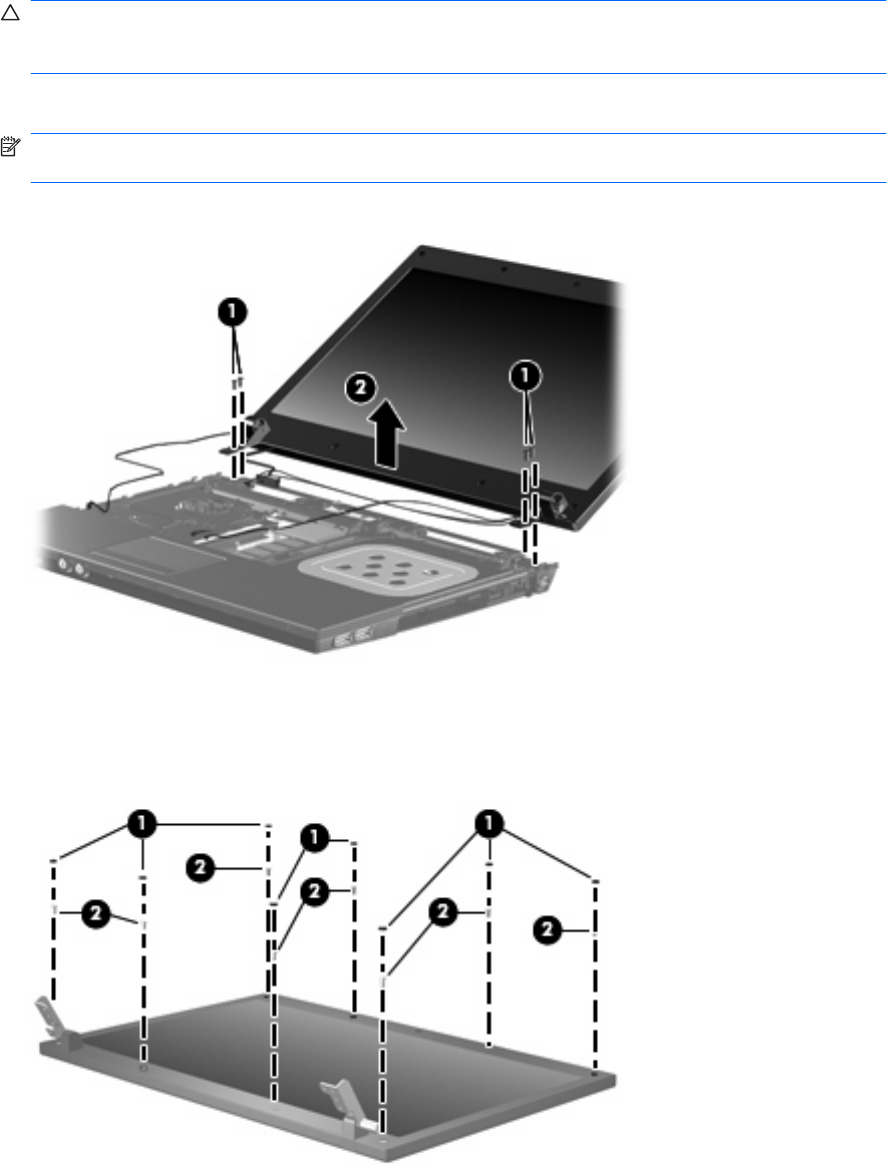
Remove the display assembly:
1. Position the computer right-side up with the front toward you.
2. Open the computer as far as possible.
CAUTION: Support the display assembly when removing the following screws. Failure to support
the display assembly can result in damage to the display assembly and other computer
components.
3. Remove the four Phillips PM2.5×4.5 screws (1) that secure the display assembly to the computer.
NOTE: When replacing the display assembly, only replace the four bottom screws. The top screw
on each side is replaced when you install the top cover.
4. Lift the display assembly up and off the computer (2).
5. If it is necessary to replace the display bezel, display enclosure, or display hinges, remove the eight
rubber screw covers (1) and the eight Phillips PM2.5×6.0 screws (2) that secure the display bezel
to the display assembly. The rubber screw covers are available in the Rubber Kit, spare part number
535793-001.
98 Chapter 4 Removal and replacement procedures