Notice The information in this guide is subject to change without notice. Compaq Computer Corporation shall not be liable for technical or editorial errors or omissions contained herein; nor for incidental or consequential damages resulting from the furnishing, performance, or use of this material. This guide contains information protected by copyright. No part of this guide may be photocopied or reproduced in any form without prior written consent from Compaq Computer Corporation.
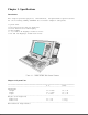
Chapter 1. Specifications Introduction This chapter provides physical, environmental, and performance specifications for the following COMPAQ PORTABLE 486c Personal Computer subsystems: o o o o o o System Unit Full Function 101/102 Key Keyboard Active Matrix Color VGA Display Power Supply 3 1/2 inch 1.44 Megabyte Diskette Drive 210 and 120 Megabyte Fixed Disk Drives Chapter 1.1 System Unit ============================================================================= U.S.
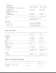
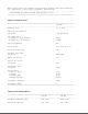
Temperature Operating 50oF to 104oF 10oC to 40oC Nonoperating -22oF to 140oF -30oC to 60oC Relative Humidity (noncondensing) Operating 20% to 80% 20% to 80% Nonoperating 5% to 90% 5% to 90% Maximum Unpressurized Altitude Operating 10,000 ft 3,050 m Nonoperating 30,000 ft 9,150 m ----------------------------------------------------------------------------Cooling 12 VDC fan 12 VDC fan ----------------------------------------------------------------------------Shock 40g, 11 ms, half sine (nonoperating) -------
Width 8.3 inch 21.1 cm ----------------------------------------------------------------------------Diagonal Size 10.4 inch 26.
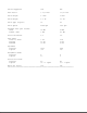
NOTE: These values are maximum values based on nominal operating conditions for temperature, line voltage, frequency, and altitude. ----------------------------------------------------------------------------* 60W maximum available through EISA expansion slots. ============================================================================= Chapter 1.5 Diskette Drive ============================================================================= 1.
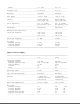
Drives Supported One One Form Factor 3 1/2 inch 3 1/2 inch Drive Height 1 inch 1 inch Drive Weight 1.3 lb 1.3 lb Drive Type (logical) 51 50 Drive Speed 4500 rpm 3399 rpm Transfer Rate (per second) Head Buffer (max) 20 MB 5 MB 12 MB 4.
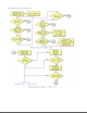
Chapter 2. Power On Self Test (POST) Introduction This chapter lists the subassemblies checked by the Power On Self Test (POST) and briefly describes the types of error codes that can occur. The chapter also includes problem isolation procedures and a flowchart for quick reference. Chapter 2.1 POST POST is a series of diagnostic tests that runs automatically on the COMPAQ PORTABLE 486c Personal Computer when it is turned on.
5. Access the fixed disk drive. You will know that the fixed disk drive password is set when the DriveLock icon (see illustration of DriveLock icon below) appears on the screen. If this occurs, you must enter the fixed disk drive password to continue. IMPORTANT: It is not necessary to access the fixed disk drive in order to run the Diagnostics diskette; however, complete system testing cannot be done without access to the complete system.
1. Disconnect the AC power. 2. Disassemble the computer to reach the I/O board (refer to Chapter 5). 3. Locate the power on password switch (SW5) on the I/O board; set the switch to ON (Figure 2-1). 4. Reconnect AC power. 5. Turn on the computer and allow it to complete POST. 6. Turn the computer off. 7. Set switch SW5 to OFF. 8. Disconnect AC power. 9. Reassemble the computer (refer to Chapter 5). 10. Reconnect the AC power. 11. Turn on the computer and allow it to complete POST.
troubleshooting information.
Chapter 3. Error Messages and Codes This chapter contains Power On Self Test (POST) messages, Diagnostic error codes, and memory error codes for the COMPAQ PORTABLE 486c Personal Computer. The messages and codes appear in tables that list the message or error code, a description of the error or its probable cause, and the action recommended to resolve the error condition. Chapter 3.
Mismatch configuration not updated 174 - EISA Configuration/ Slot Mismatch 1 Short EISA board not found 175 - EISA Configuration/ Slot Mismatch 1 Short EISA board added, configuration not updated 176 - Slot with Unreadable ID 1 Short EISA board in slot that should contain ISA board 177 - Configuration 1 Short Incomplete EISA Not Complete configuration ----------------------------------------------------------------------------Message Beeps Probable Cause Recommended Action -----------------------
and retest. Run Diagnostics. Replace the I/O board. ----------------------------------------------------------------------------605 - Diskette Drive 2 Short Mismatch in Run COMPAQ EISA Type Error drive type Configuration utility. ----------------------------------------------------------------------------610 - External None External Storage Turn on External Storage Module Module connected Storage Module or Failure. Hit but turned off disconnect from F1 when ready. computer.
----------------------------------------------------------------------------1782 - Disk None Fixed disk drive 1. Run Diagnostics. Controller controller error 2. Check and/or Failure replace the power distribution board. 3. Replace the fixed disk drive. ----------------------------------------------------------------------------Message Beeps Probable Cause Recommended Action ----------------------------------------------------------------------------1790 - Disk 0 Error None Fixed disk drive 1.
Diagnostic error codes occur if the system recognizes a problem while running the Diagnostics program (refer to the SUPPORT SOFTWARE MAINTENANCE AND SERVICE GUIDE for additional information on running the Diagnostics software). These error codes help identify possible defective subassemblies. Tables 3-2 through 3-12 list possible error codes, a description of the error condition, and the action required to resolve the error condition.
unexpected 101 - 95 Coprocessor and processor board conflict 101 - 96 Refer to Authorized Compaq Dealer Service Bulletin No. 84. ----------------------------------------------------------------------------Error Recommended Code Description Action ----------------------------------------------------------------------------102 - 01 Coprocessor initial status The following steps apply word incorrect to error codes 102 - xx: 1. Run COMPAQ EISA 102 - 02 Coprocessor initial control Configuration utility.
103 - 03 DMA word controller test failed 104 - 01 Interrupt controller master test failed 104 - 02 Interrupt controller slave test failed 104 - 03 Interrupt controller software RTC is inoperative 105 - 01 Port 61 bit 6 not at zero 105 - 02 Port 61 bit 5 not at zero 105 - 03 Port 61 bit 3 not at zero 105 - 04 Port 61 bit 1 not at zero 105 - 05 Port 61 bit 0 not at zero 105 - 06 Port 61 bit 5 not at one 105 - 07 Port 61 bit 3 not at one 105 - 08 Port 61 bit 1 not at one -----------------
109 - 02 CMOS clock rollover test failed 109 - 03 CMOS clock test, CMOS not properly initialized ----------------------------------------------------------------------------Error Recommended Code Description Action ----------------------------------------------------------------------------110 - 01 Programmable timer load Replace the processor board data test failed and retest for error codes 103 - xx through 114 - xx. 110 - 02 Programmable timer dynamic test failed 110 - 03 Programmable Timer No.
113 - 50 BIOS dispatch of processor 113 - 51 Processor is unavailable or nonexistent 113 - 52 Time out waiting for completion of test 113 - 54 Time out waiting for serial semaphore 113 - 56 Unexpected interrupt occurred during test 114 - 01 Speaker test failed ============================================================================= Table 3-3.
204 - 02 Error during saving program memory in address test ----------------------------------------------------------------------------Error Recommended Code Description Action ----------------------------------------------------------------------------204 - 03 Error during restore of The following steps apply program memory in to error codes 203 - xx address test through 211 - xx: 1. Replace the memory 204 - 04 A20 address test failed module and retest. 2.
page not present 211 - xx Random Pattern Test 211 - 01 Memory random pattern test failed 211 - 02 Error during saving program memory and random pattern in write/read test 211 - 03 Error during restore of program memory and random pattern in write/read test 211 - 04 Insufficient memory to perform test 211 - 05 Inverted pattern compare, but RAM correct ============================================================================= Table 3-4.
----------------------------------------------------------------------------Error Recommended Code Description Action ----------------------------------------------------------------------------303 - 08 Keyboard LED test, The following steps apply command byte restore to error codes 301 - xx test failed through 304 - xx: 1. Check the keyboard 303 - 09 Keyboard LED test, LEDs connection. If failed to light disconnected, turn off the computer and 304 - 01 Keyboard typematic test connect the keyboard.
402 - 09 Printer interrupt and data register failed 402 - 10 Printer interrupt and control register failed ----------------------------------------------------------------------------Error Recommended Code Description Action ----------------------------------------------------------------------------402 - 11 Printer interrupt, data, and The following steps apply control register failed to error codes 401 - xx through 403 - xx: 402 - 12 Printer interrupt and 1.
507 - 01 Video 40 x 25 Mode Test Failed 508 - 01 Video 320 x 200 Mode Color Set 0 Test Failed 509 - 01 Video 320 x 200 Mode Color Set 1 Test Failed 510 - 01 Video 640 x 200 Mode Test Failed 511 - 01 Video Screen Memory Page Test Failed 512 - 01 Video Gray Scale Test Failed 514 - 01 Video White Screen Test Failed 516 - 01 Video Noise Pattern Test Failed ============================================================================= Table 3-7.
610 - 02 Exceeded maximum hard error limit 610 - 03 Previously exceeded maximum soft error limit ----------------------------------------------------------------------------Error Recommended Code Description Action ----------------------------------------------------------------------------610 - 04 Previously exceeded The following steps apply maximum hard error limit to error codes 600 - xx through 610 - xx: 610 - 05 Failed to reset controller 1. Replace the diskette and retest.
3. Check and/or replace drive cable and retest. 4. Replace the I/O board and retest. ----------------------------------------------------------------------------699 - 00 Diskette drive/media ID 1. Replace the media. error, rerun COMPAQ 2. Run COMPAQ EISA EISA Configuration utility Configuration utility. ============================================================================= Table 3-8.
1101 - 14 Serial Port Test; DRIVER/RECEIVER data failure 1101 - 15 Serial port test modem detection 1101 - 16 Serial port test, modem ROM checksum 1101 - 17 Serial port test, tone detection 1101 - 18 Serial port test, COM3 set to invalid interrupt 1101 - 19 Serial port test, COM4 set to invalid interrupt 1109 - 01 Clock register initialization failure 1109 - 02 Clock register rollover failure ----------------------------------------------------------------------------Error Recommended Code De
1201 - 08 UART TX/RX buffer failure 1201 - 09 INTERRUPT circuit failure 1201 - 10 COM1 set to invalid interrupt 1201 - 11 COM2 set to invalid interrupt 1201 - 12 DRIVER/RECEIVER control signal failure ----------------------------------------------------------------------------Error Recommended Code Description Action ----------------------------------------------------------------------------1201 - 13 UART control signal The following steps apply interrupt failure to error codes 1201 - xx through 1
1202 - 21 Modem timed out waiting for SYNC (analog loopback answer mode) 1202 - 22 Modem timed out waiting for modem response (analog loopback answer mode) 1202 - 23 Modem exceeded data block retry limit (analog loopback answer mode) 1203 - xx Modem External Termination Test 1203 - 01 Modem external TIP/RING failure 1203 - 02 Modem external DATA TIP/RING failure 1203 - 03 Modem line termination failure 1204 - xx Modem Auto Originate Test 1205 - xx 2. 3.
1210 - 08 Modem timed out waiting for remote response 1210 - 09 Modem exceeded maximum redial limit 1210 - 10 Line quality prevented remote connection 1210 - 11 Modem timed out waiting for remote connection 1210 - 17 Tone detection failure ============================================================================= Table 3-10.
select test failed 2. 1716 - xx Fixed disk drive conditional format test failed 1717 - xx Fixed disk drive Error Correction Code test failed 1719 - xx Fixed disk drive power mode test 1719 - 01 Exceeded maximum soft error limit 1719 - 02 Exceeded maximum hard error limit 1719 - 03 Previously exceeded maximum soft error limit 1719 - 04 Previously exceeded maximum hard error limit 1719 - 05 Failed to reset controller 1719 - 06 Fatal error while reading 3. drive and retest.
1719 - 47 Failed to park heads 1719 - 48 Failed to move disk table to RAM ----------------------------------------------------------------------------Error Recommended Code Description Action ----------------------------------------------------------------------------1719 - 49 Failed to read media in The following steps apply file write test to error codes 1700 - xx through 1719 - xx: 1719 - 50 Failed file I/O write test 1. Replace the fixed disk drive and retest. 1719 - 51 Failed file I/O read test 2.
1719 - 68 Failed to read long 1719 - 69 Failed to read drive size from controller 1719 - 70 Failed translate mode 1719 - 71 Failed nontranslated mode 1719 - 72 Bad track limit exceeded 1719 - 73 Previously exceeded bad track limit 1719 - 74 Failed sleep mode 1719 - 75 Failed idle mode 1719 - 76 Failed standby mode 1719 - 77 Failed to change mode 1719 - 78 Exceeded spinup time limit ============================================================================= Table 3-11.
1906 - 08 Unable to servo write ----------------------------------------------------------------------------Error Recommended Code Description Action ----------------------------------------------------------------------------1906 - 09 Unable to format The following steps apply to error codes 1901 - xx 1906 - 10 Format mode error through 1906 - xx: 1. Replace the tape 1906 - 11 Drive recalibration error cartridge and retest. 2. Replace the tape 1906 - 12 Tape not servo written drive and retest. 3.
1906 - 34 No data detected 1906 - 35 Power on reset occurred 1906 - 91 Power lost during test ============================================================================= Table 3-12.
2420 - 01 Video attribute test failed 2421 - 01 Video 640 x 200 graphics mode test failed 2422 - 01 Video 640 x 350 16 color set test failed 2423 - 01 Video 640 x 350 64 color set test failed 2424 - 01 Video monochrome text mode test failed 2425 - 01 Video monochrome graphics mode test failed 2431 - xx Video 640 x 480 graphics mode test failed 2432 - xx Video 320 x 200 graphics mode test failed ============================================================================= Table 3-13.
| | | | | | | | | | | | | | | | | | | | | | | | | | | | | | | | | | | | | | | | | | | | | 08, 10, 20, 40, 80, ?? 00 01 02 04 08 10 20 40 80 ?? = = = = = = = = = = parity bit data bit 0 data bit 1 data bit 2 data bit 3 data bit 4 data bit 5 data bit 6 data bit 7 unable to determine failed data bit. ------------------------ Failed byte. Values are 0, 1. -------------------------- Always 000. ----------------------------- Failed address.
Chapter 4. Illustrated Parts Catalog This chapter provides an illustrated parts breakdown and identifies the spare parts for the standard features of the COMPAQ PORTABLE 486c Personal Computer. Chapter 4.
Table 4-1. System Unit ============================================================================= Description Spare Part Number ----------------------------------------------------------------------------1. System Chassis 128937-001 2. Front Bezel 128946-001 3. Rear Panel Handle Connector Cover Enhanced Option Cover 128938-001 4. Base Panel 128948-001 5. Tilt Base 135999-001 6. Power Supply 128898-001 7. Fan Assembly 128901-001 8. Keylock 135901-001 9. AC Power Cord (U.S.
============================================================================= Description Spare Part Number ----------------------------------------------------------------------------1. Front Bezel 128946-001 2. Display Assembly Display Shield 128902-001 3. Backlight Assembly Display Shield 136964-001 4. Video Cable 128903-001 5. Display Inverter Board 128900-001 ============================================================================= Mass Storage Devices Table 4-3.
Table 4-4. Cables ============================================================================= Description Spare Part Number ----------------------------------------------------------------------------1. Power Distribution Board 128935-001 2.
Table 4-5. COMPAQ PORTABLE 486c Personal Computer Processor Board Connectors ============================================================================= 1. Memory Module Connectors, Slots 2, 3, and 4 2. Intel 486 33 MHz Microprocessor Connector 3. System ROM Connector 4. Real Time Clock/Battery Connector 5. Memory Module Connector, Slot 1 ============================================================================= I/O Board Table 4-6.
Table 4-7. Processor and Standard Board Assemblies and Subassemblies ============================================================================= Item Description Spare Part Number ----------------------------------------------------------------------------1. Processor Board 128897-001 2. 4 Megabyte Memory Module 118741-001 3. System ROM 128939-001 4. Real Time Clock/Battery 126570-001 5. I/O Board 128949-001 6. Video Board 128899-001 7. Display Inverter Board 128900-001 8.
Table 4-8. Keyboards ============================================================================= Description Spare Part Number ----------------------------------------------------------------------------1. U.S. English 128958-001 2. Keyboard template 128934-001 3. UK English 128958-003 * 4. German 128958-004 * 5. French 128958-005 * 6. Italian 128958-006 * 7. Spanish 128958-007 * 8. Danish 128958-008 * 9. Norwegian 128958-009 * 10. Swedish/Finnish 128958-010 * 11. Swiss 128958-011 * 12.
----------------------------------------------------------------------------System Unit: System Chassis 128937-001 Front Bezel 128946-001 Rear Panel 128938-001 Handle Connector Cover Enhanced Option Cover Base Panel 128948-001 Tilt Base 135999-001 Power Supply 128898-001 Fan Assembly 128901-001 Keylock 135901-001 AC Power Cord (U.S.
Belgian 128958-018 Documentation: Service Aids Kit 105264-001 Maintenance and Service Guides: COMPAQ PORTABLE 486c Personal Computer 128987-001 Options and Peripherals Volume 1 120577-001 Options and Peripherals Volume 2 120577-001 Options and Peripherals Volume 3 120577-001 Support Software 120576-001 Operations Guide 128940-001 COMPAQ PORTABLE 486c PERSONAL COMPUTER TECHNICAL REFERENCE GUIDE 128822-001 COMPAQ SERVICE QUICK REFERENCE GUIDE 106854-001 Diagnostics 3 1/2 inch 720 Kbyte Diskette * User Progr
Screw Kit 6-32, MA, TH, T-15, CS 136967-001 Screw Kit 6-32 x 1/4, Torx, TT, HI, T/WSr 119548-001 Screw Kit 6-32 x 1/4, S-Torx, PNHD 136966-001 Screw Kit 6-32 x 1/4, TAPTITE, HT 128212-001 Screw Kit 136974-001 6-32 x 1/2, S-Torx, TT =============================================================================
Chapter 5. Removal and Replacement Procedures Introduction This chapter provides module level removal and replacement procedures for the COMPAQ PORTABLE 486c Personal Computer. After completing all removal and replacement procedures, run the Diagnostics program to verify that all components operate properly. Refer to the SUPPORT SOFTWARE MAINTENANCE AND SERVICE GUIDE for information on installing new or updated utilities when adding or removing options. Chapter 5.
grounding are necessary precautions to prevent damage. precautions to protect equipment from static damage: Use the following o To avoid hand contact, transport products in static safe containers such as tubes, bags, or boxes. o Protect all electrostatic parts and assemblies by conductive or approved containers or packaging. o Keep electrostatic sensitive parts in their containers until they arrive at static free stations. o Place items on a grounded surface before removing them from their container.
Grounding Workstations To provide a grounded workstation, do the following: o Cover workstations with approved static dissipating material. Provide a wrist strap connected to work surface and properly grounded tools and equipment. o Use static dissipating mats, heel straps, or air ionizers to give added protection. o Handle electrostatic sensitive components, parts, and assemblies by the case or PCB laminate. Handle them only at static free workstations. o Avoid contact with pins, leads, or circuitry.
o Conductive foam o Conductive table top workstations with ground cord of 1 megohm resistance o Static dissipating table or floor mats with hard tie to ground o Field service kits o Static awareness labels o Wrist straps and footwear straps providing 1 megohm ñ 10% resistance o Material handling packages - Conductive plastic bags - Conductive plastic tubes - Conductive tote boxes - Metal tote boxes - Opaque shielding bags - Transparent metallized shielding bag - Transparent shielding tubes Chapter 5.
5.9 5.10 5.11 5.12 5.13 5.14 5.15 5.16 | | | | | | | | |-| |-| | | |-| | | | | | |-| |-- | | |-| |-| |-- |-- Real Time Clock/Battery POWER SUPPLY FAN ASSEMBLY I/O BOARD BASE PANEL MASS STORAGE DEVICES |-- Diskette Drive |-- Fixed Disk Drive ACTIVE MATRIX COLOR DISPLAY |-- Front Bezel |-- Display Assembly |-- Backlight Assembly |-- Display Inverter Board |-- Speaker Assembly POWER DISTRIBUTION BOARD KEYLOCK Chapter 5.
3. Disconnect all external devices (printer, monitor, and other devices) from the computer. >>>>>>>>>>>>>>>>>>>>>>>>>>>>>>>>>>>>>>><<<<<<<<<<<<<<<<<<<<<<<<<<<<<<<<<<<<<<< CAUTION Static electricity can damage the CMOS components. Be sure that you are properly grounded before performing any of the following procedures. >>>>>>>>>>>>>>>>>>>>>>>>>>>>>>>>>>>>>>><<<<<<<<<<<<<<<<<<<<<<<<<<<<<<<<<<<<<<< CAUTION Screws in this system are not interchangeable.
2. Using a nonconductive probe, remove the access cover (Figure 5-3). 3. Disconnect the keyboard cable by gently pulling the keyboard connector tab (Figure 5-4).
4. Carefully remove the keyboard cable from the cable slot (Figure 5-4). To replace the keyboard, reverse the steps in the above illustrations. Chapter 5.6 Rear Panel To remove the rear panel, complete the following steps: 1. Push the tilt adjustment buttons on the sides of the computer in and tilt the display assembly forward (Figure 5-5).
2. Lift the handle and remove two screws, using a Torx T-15 screwdriver (Figure 5-5). 3. Pull the rear panel out and up, until the bottom latches are released from the slots (Figure 5-6). To replace the rear panel, complete the following steps: 1.
with the appropriate slots. 2. Slide the rear panel down and forward, and secure with the two screws using a Torx T-15 screwdriver. Chapter 5.7 Options Cover To remove the options cover, complete the following steps: 1. Remove the rear panel (Section 5.6). 2. Using a Torx T-15 screwdriver, remove three screws from the top of the options cover (Figure 5-7). 3. Loosen two slotted screws (Figure 5-8). 4. Lift the options cover off of the slotted screws (Figure 5-8).
To replace the options cover, reverse the steps in the above illustration. Chapter 5.8 Standard Boards Video Board To remove the video board, complete the following steps: 1. Remove the rear panel (Section 5.6). 2. Remove the options cover (Section 5.7). 3. Remove any expansion boards from the expansion slots (Refer to the COMPAQ PORTABLE 486c Personal Computer Reference Guide).
(Figure 5-9). 5. Carefully disconnect the video cable from the video board (Figure 5-9). 6. Using a Torx T-10 screwdriver, remove the screw securing the video board (Figure 5-9). 7. Carefully pull the video board out of the slot (Figure 5-9). To replace the video board, reverse the steps in the above illustration. Processor Board To remove the processor board, complete the following steps: 1. Remove the rear panel (Section 5.6). 2. Remove the options cover (Section 5.7). 3.
5. Carefully pull the processor board out of the slot (Figure 5-10). To replace the processor board, reverse the steps in the above illustration. System ROM To remove the system ROM from the processor board, complete the following steps: 1. Remove the rear panel (Section 5.6). 2. Remove the options cover (Section 5.7). 3. Remove the video board (Section 5.8). 4. Remove the processor board. 5. Locate the system ROM on the processor board (Figure 5-11).
6. Using the ROM removal tool, grasp the ROM and gently pull up until it is released from the socket (Figure 5-11). To replace the system ROM, reverse the steps in the above illustration. NOTE: When replacing the system ROM, align Pin 1 with the dot on the system ROM socket. Real Time Clock/Battery To remove the real time clock/battery, complete the following steps: 1. Remove the rear panel (Section 5.6). 2. Remove the options cover (Section 5.7). 3. Remove the video board (Section 5.8). 4.
>>>>>>>>>>>>>>>>>>>>>>>>>>>>>>>>>>>>>>><<<<<<<<<<<<<<<<<<<<<<<<<<<<<<<<<<<<<<< WARNING The real time clock/battery contains a lithium battery that may explode if mishandled. Do not abuse, recharge, disassemble, or dispose of in fire. Use only replacement real time clock/battery modules supplied by Compaq Computer Corporation (part no. 126570-001).
3. Using a Torx T-15 screwdriver, remove three screws securing the power supply to the I/O board (Figure 5-13). 4. Pull out the power supply with the switch bezel attached (Figure 5-13). 5. Remove the switch bezel from the power supply (Figure 5-13). To replace the power supply, reverse the steps in the above illustration. Chapter 5.10 Fan Assembly To remove the fan assembly, complete the following steps: 1. Remove the rear panel (Section 5.6). 2. Remove the options cover (Section 5.7). 3.
4. Using a Torx T-10 screwdriver, remove the screw securing the fan assembly (Figure 5-14). 5. Slide the fan assembly out (Figure 5-14). To replace the fan assembly, reverse the steps in the above illustration. Chapter 5.11 I/O Board To remove the I/O board, complete the following steps: 1. Remove the rear panel (Section 5.6). 2. Remove the options cover (Section 5.7). 3. Remove the video board (Section 5.8). 4. Remove the processor board (Section 5.8). 5. Remove the power supply (Section 5.
8. Disconnect the fan assembly cable (Figure 5-15). 9. Using a Torx T-10 screwdriver, remove the screw securing the internal keyboard connector to the display pan (Figure 5-15). 10. Using a Torx T-15 screwdriver, remove seven screws securing the I/O board (Figure 5-15). To replace the I/O board, reverse the steps in the above illustration. Chapter 5.
2. Position the computer on the rear panel (Figure 5-16). 3. Using a Torx T-15 screwdriver, remove the screw from the base panel (Figure 5-16). 4. Remove the base panel by sliding it out toward the diskette drive side of the computer (Figure 5-16). To replace the base panel, reverse the steps in the above illustration. Chapter 5.13 Mass Storage Devices Diskette Drive To remove the diskette drive, complete the following steps: 1. Remove the base panel (Section 5.12). 2.
3. Using a Torx T-15 screwdriver, remove the screws securing the diskette drive cage; then swing the drive cage out (Figure 5-17). 4. Using a Torx T-15 screwdriver, remove four screws securing the diskette drive to the drive cage (Figure 5-17). To replace the diskette drive, reverse the steps in the above illustration. Fixed Disk Drive To remove the fixed disk drive, complete the following steps: 1. Remove the base panel (Section 5.12). 2.
3. Using a Torx T-15 screwdriver, remove the screws securing the fixed disk drive cage; then swing the drive cage out (Figure 5-18). 4. Lift the fixed disk drive out of the cage and remove the shock mounts (Figure 5-19). To replace the fixed disk drive, reverse the steps in the above illustrations.
Chapter 5.14 Active Matrix Color Display Front Bezel To remove the front bezel, complete the following steps: 1. Remove the keyboard (Section 5.5). 2. Pull the brightness and volume controls off (Figure 5-20). 3. Remove four plastic screw covers from the front bezel (Figure 5-20). >>>>>>>>>>>>>>>>>>>>>>>>>>>>>>>>>>>>>>><<<<<<<<<<<<<<<<<<<<<<<<<<<<<<<<<<<<<<< WARNING The display inverter board contains high voltage.
Display Assembly To remove the display assembly, complete the following steps: 1. Remove the keyboard (Section 5.5). 2. Remove the front bezel (Section 5.14). >>>>>>>>>>>>>>>>>>>>>>>>>>>>>>>>>>>>>>><<<<<<<<<<<<<<<<<<<<<<<<<<<<<<<<<<<<<<< WARNING The display inverter board contains High Voltage. Avoid contact with all surfaces of the display inverter board when removing the display assembly.
>>>>>>>>>>>>>>>>>>>>>>>>>>>>>>>>>>>>>>><<<<<<<<<<<<<<<<<<<<<<<<<<<<<<<<<<<<<<< CAUTION When removing or inserting cables with ZIF connectors, do not pull, twist, or apply tension to cables. >>>>>>>>>>>>>>>>>>>>>>>>>>>>>>>>>>>>>>><<<<<<<<<<<<<<<<<<<<<<<<<<<<<<<<<<<<<<< NOTE: The ZIF connectors in this product have mechanical latches that either slide forward and lift up or slide up to open. Be sure the latches on the ZIF connectors are opened before attempting to remove the cable. 4.
4. Place the display assembly screen down on a soft, clean surface. 5. Using a Phillips screwdriver, remove the four screws securing the display assembly to the backlight assembly (Figure 5-22). 6. Carefully release the display assembly cables from the four corner brackets (Figure 5-22). 7. Release the five tabs securing the backlight assembly to the display assembly (Figure 5-22). To replace the backlight assembly, reverse the steps in the above illustration.
1. Remove the keyboard (Section 5.5). 2. Remove the front bezel (Section 5.14). 3. Remove the display assembly (Section 5.14). >>>>>>>>>>>>>>>>>>>>>>>>>>>>>>>>>>>>>>><<<<<<<<<<<<<<<<<<<<<<<<<<<<<<<<<<<<<<< WARNING The display inverter board contains high voltage. surfaces of the board. Avoid contact with all >>>>>>>>>>>>>>>>>>>>>>>>>>>>>>>>>>>>>>><<<<<<<<<<<<<<<<<<<<<<<<<<<<<<<<<<<<<<< CAUTION When removing or inserting cables with ZIF connectors, do not pull, twist, or apply tension to cables.
6. Pull the display inverter board insulator aside to gain access to the screws (Figure 5-23). 7. Using a Torx T-15 screwdriver, remove five screws securing the display inverter board (Figure 5-23). To replace the display inverter board, reverse the steps in the above illustration. Speaker Assembly To remove the speaker assembly from the display inverter board, complete the following steps: 1. Remove the keyboard (Section 5.5). 2. Remove the front bezel (Section 5.14). 3.
4. Carefully release the speaker assembly tabs and remove the speaker assembly from the display inverter board (Figure 5-24). To replace the speaker assembly, reverse the steps in the above illustration. Chapter 5.15 Power Distribution Board To remove the power distribution board, complete the following steps: 1. Remove the keyboard (Section 5.5). 2. Remove the front bezel (Section 5.14).
on the display inverter board (Figure 5-25). 4. Turn the computer around and remove the rear panel (Section 5.6). 5. Remove the options cover (Section 5.7). 6. Remove the video board (Section 5.8). 7. Remove the processor board (Section 5.8). 8. Remove the power supply (Section 5.9). 9. Remove the fan assembly (Section 5.10). 10. Remove the I/O board (Section 5.11). 11. Remove the base panel (Section 5.12). 12.
13. Using a Torx T-15 screwdriver, remove four screws securing the power distribution board (Figure 5-27). 14. Carefully pull the I/O cables, diskette drive cable, fixed disk drive cable, and power cable through their respective slots and remove the power distribution board (Figure 5-27). To replace the power distribution board, reverse the steps in the above illustrations.
Chapter 5.16 Keylock To remove the keylock, complete the following steps: 1. Remove the rear panel (Section 5.6). 2. Remove the options cover (Section 5.7). 3. Using a flathead screwdriver, remove the metal clip securing the keylock (Figure 5-28). 4. Pull the keylock out of the computer (Figure 5-28).
To replace the keylock, reverse the steps in the above illustration. Chapter 5.17 Memory Expansion Some of the memory expansion alternatives for the COMPAQ PORTABLE 486c Personal Computer are shown in Table 5-3. Memory modules can be added in combinations of 2, 4, and 8 megabytes for a total of 32 megabytes. NOTE: Memory modules can be installed in any combination and in any available slot. However, slot 1 must contain a memory module. Table 5-3.
4 MB 2 MB 8 MB 8 MB 22 MB 4 MB 4 MB 8 MB 8 MB 24 MB 4 MB 8 MB 8 MB 8 MB 28 MB | | | | | | | | | | 8 MB 8 MB 8 MB 8 MB 32 MB =============================================================================
Chapter 6. Jumper and Switch Information This chapter provides the switch settings for the COMPAQ PORTABLE 486c Personal Computer I/O board. The I/O board contains six switches. The default settings shown in the following table are set for the computer as configured by Compaq Computer Corporation. These settings need to be changed only when the system configuration changes. Table 6-1 lists the switch settings and describes the function of each switch.
SW5 ON OFF Enabled Disabled Controls the power on password. OFF is the default position and enables the power on password feature. ON will clear the power on password. ----------------------------------------------------------------------------SW6 ON Enabled Allows the configuration OFF Disabled memory to be cleared. OFF is the default position and allows configuration memory to remain unchanged. ON clears the configuration memory.