
Product manual


R
2800 LAURA LANE • MIDDLETON, WI 53562 • (800) 288-9383 • FAX (608) 836-9044 • www.tcsbasys.com
4
either be done from the face of the controller using the
keypad and display or by individually direct connecting
controllers to the QD2040. On units without displays,
controller addressing is done by direct connect to
QD2040. (see Control Addressing section and Controller
Programming with the QD2040 in the Setup and
Programming Section)
Mounting
The QD2040 is designed to either be mounted in a
PP2000 panel, on a wall or it may be set on a table
or shelf. The PP200 panel, is custom fabricated and
designed specifically to house the QD2040 and various
other controls. When mounting to a wall, use the
QD2040 mounting bracket and select a sturdy wall made
of masonry, wood or metal. When mounting to dry
wall, it is recommended that you first attach a wood or
metal back plate to the wall and then mount the QD2040
bracket assembly to the back plate.
When selecting a location to mount the QD2040, be
sure to allow room for cable connections and locate the
unit in an area away from excessive dust, heat sources,
moisture, or direct sunlight. The ideal environment is
a server room. The temperature of the room can not
exceed 77ºF (25ºC), with good ventilation manditory.
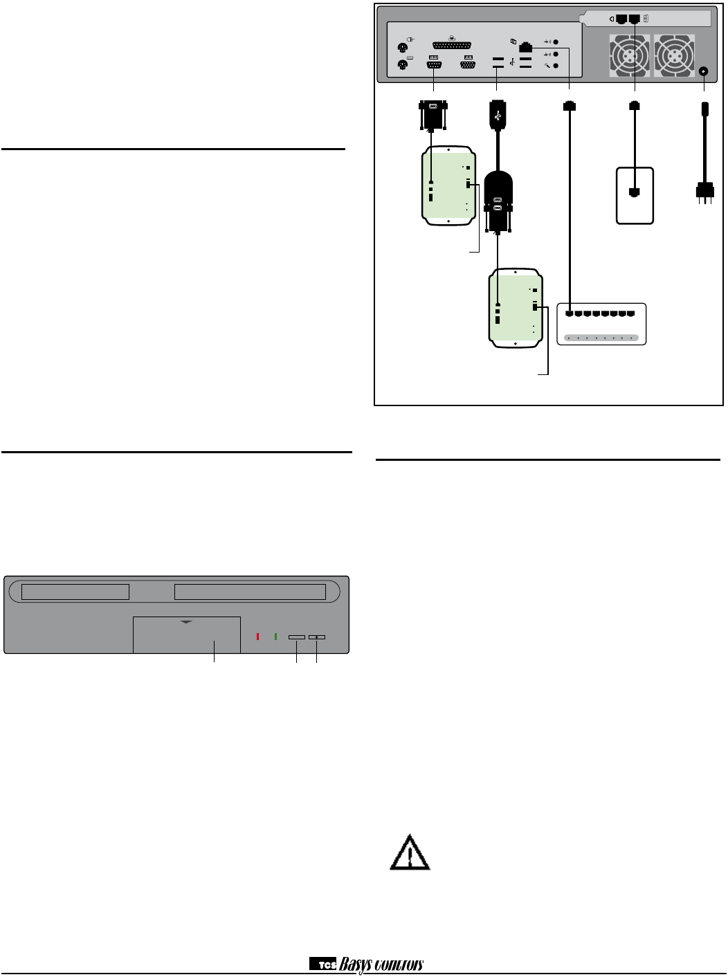
Connections
To power the QD2040, attach the power cord to the
QD2040 and insert the power plug into a 120 VAC
socket. Upon connection the QD2040 may power up
automatically. If it does not, simply press the power
button.
To connect the QD2040 to a LAN, connect an Ethernet
cable (not included) to the RJ-45 connection on the
back of the QD2040. Connect the other end to the LAN
network hub.
For dial-in access to the QD2040 or for dial-up ISP
function, connect phone line from modem connection on
QD2040 to phone line jack. For dial-in function it is not
necessary to have dedicated phone line. A line sharing
interface may be utilized to share line with another line
such as a fax line. A dedicated line is required for dial-up
ISP functionality.
Controller Network Wiring and Setup
To access your controllers through Ubiquity browser
software, you will need to create an "RS485" network by
connecting all of the controllers "A" terminals together,
"B" terminals together and REF together, using 18 or 20
AWG twisted, shielded 3 conductor (triple) wire.
If a port has more than 32 Controllers or is longer than
4000 Ft., you will need a bus repeater, QD1011a. You
will need a bus repeater for each group of 32 units.
When connecting controllers on a network, you may use
any one of a number of wiring configurations, such as
"daisy chain", "star", etc., as long as all "A" terminals
are connected to a common wire all "B" terminals are
connected to a different, yet common wire and all “Ref”
terminals conected to a third wire.
The integrity of the "A", "B" and “REF” wiring runs must
be maintained or the network will not communicate
properly.
CAUTION:You must maintain proper polarity of A, B
and REF connections (see figure). All shields
must be tied together, taped off to prevent
any accidential connections then grounded
at one end of the network. Caution should
be taken to avoid running wire near power
wires, frequency drives, fluorescent lights,
ballasts, etc., which can all compromise the
communications signal. Care should also
be taken to leave as little wire exposed as
possible.
POWER
Phone line
Power cord
Modem
Power
ETHERNET HUB
Ethernet
QD1010
RS485
Serial
To RS485
Control Network
QD1010
PI1000
USB
To RS485
Control Network
Ethernet Cable (Not Included)
* If additional ports are
needed, a multi-port
USB hub can be used.
Additional
USB Ports
Reset
Button
PWR
RESET
HOO
Power
Button