User’s Guide Compaq P710 Color Monitor Compaq P910 Color Monitor Compaq P1210 Color Monitor
CONTENTS Features ............................................................ 1 Internal Preset Memory Capability ................... 3 Power Management Function .......................... 3 DDC .................................................................. 3 Location Considerations .................................. 4 Cleaning Your Monitor ..................................... 4 Unpacking ........................................................ 5 Tilt/Swivel Base ......................................
1 INTRODUCTION • For use in a variety of applications, the monitor complies with UL 1950, CSA C22.2 No.950 and EN60950 for safety, FCC Class-B, VCCI Class-B and EN55022 Class-B for EMI, MPR-II, ISO 9241-3, ISO9241-7 and ISO9241-8 for ergonomics. The monitor also complies with TCO’99 guideline for environmental safe use. • The world's standard DIAMONDTRON NF CRT upgraded with improved focus and convergence for super sharp and pure picture images.
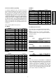
17" Model To minimize adjustment needs, the factory has preset popular display standards into the monitor, as shown in Table 1. If any of these display standards are detected by the microprocessor, the picture size and position are automatically adjusted. All of the factory presets may be overwritten by adjusting the user controls. This monitor is capable of automatically storing up to 15 additional display standards (22" model) or 16 additional display standards (17" and 19" models).
Location Considerations When setting up and using the monitor, keep the following in mind: For optimum viewing, avoid placing the monitor against a bright background or where sunlight or other light sources may reflect on the display area of the monitor. Place the monitor just below eye level. • Place the monitor away from strong magnetic or electromagnetic fields, such as high capacity transformers, electric motors, large current power lines, steel pillars, etc....
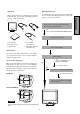
Quick Operation Chart After you unpack the box you should have all of the items indicated below. Save the box and packing materials in case you transport the monitor. To summarize the steps in connecting your computer with the color monitor and setting the necessary controls and switches, refer to the chart below. 2 1 3 Connect the color monitor and computer with the necessary cords and cables. See Section 3. INSTALLATION AND CONNECTION 5 4 Turn on the color monitor. 1. Color Monitor 2.
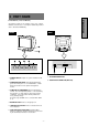
2 PART NAME ENGLISH Control Names (17" & 19" Models) See figures below for the location of the user controls, indicator and connectors. Each part is identified by number and is described individually. REAR FRONT D-SUB D-sub 7. AC POWER CONNECTOR 1. POWER SWITCH: A push-on / push-off switch for AC power. 8. SIGNAL INPUT CONNECTOR (DB9-15P) 2. POWER-ON INDICATOR: This indicator illuminates green when AC power is on, and illuminates amber when the monitor is in the power management modes. 3.
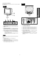
Control Names (22" Model) See figures below for the location of the user controls, indicator and connectors. REAR FRONT FRONT ENGLISH SIGNAL-A SIGNAL-B 1/2 3 SIGNAL-A SIGNAL-B 1/2 3 9 7. AC POWER CONNECTOR 1. POWER SWITCH: A push-on / push-off switch for AC power. 8. SIGNAL INPUT CONNECTOR (SIGNAL A):DB9-15P 2. POWER-ON INDICATOR: This indicator illuminates green when AC power is on, and illuminates amber when the monitor is in the power management modes. 9.
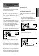
3 INSTALLATION AND CONNECTION Signal Cable Connection On the back of the monitor two kinds of plug-in connections are provided: AC power connector for the AC input, DB915P connector for video signal input. The DB9-15P(VGA) connector is provided for compatible analog RGB outputs from your computer. Connecting to VGA Compatible System AC Power Connection The figure below shows the SC-B104 cable connection to the Video Graphics Array (VGA) port in any VGA compatible system.
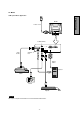
22" Model USB System Basic Application ENGLISH REAR Power Cord SIGNAL-A SIGNAL-B 21 3 DownstreamPorts SIGNAL-A SIGNAL-B 1 2 3 USB Cable Upstream Port Signal Cable Computer Scanner Camera Keyboard NOTE The computer is required to have Windows® 98 or later installed and USB functions.
Installation of USB Function 1. Power on the display monitor and then the computer. 2. Start "Enumeration" from the Windows® Desktop. NOTE NOTE • During the enumeration of the USB Hub, connect the keyboard and mouse, to the computer and not to the downstream ports on the display monitor. After the enumeration, the keyboard and mouse can be used by connecting to the downstream ports, if they are USBcompliant. • Do not unplug the USB cable during the enumerations.
4 OSD (On Screen Display) How to adjust the screen (5) Adjust by pressing or button. The monitor has an OSD(On Screen Display) function. The following procedure shows how to adjust the screen using the OSD function. (6) If you don't press any button for about 12 seconds, the OSD screen will disappear. (1) Turn on the monitor. The 22" model OSD can be turned off quickly by pressing the OSD OFF button. (2) Press button screen.
Adjustment Items 22" Model Items MOIRE CANCEL LEVEL CLAMP PULSE POSITION VIDEO LEVEL DEGAUSS POWER SAVE CONTROL LOCK OSD POSITION ALL RESET GTF AUTO ADJUST DIAGNOSIS LANGUAGE Function Adjusts the contrast level. Adjusts the black level of the screen Select the desired color from Color 1, Color 2, and Color 3 presets. Adjusts the red-color balances for the selected color. Adjusts the green-color balances for the selected color. Adjusts the blue-color balances for the selected color.
22" Model Group Icon Item Icon Item BRIGHT Press the Plus Button To decrease the contrast. To increase the contrast. To decrease the brightness. To increase the brightness. COLOR NO To select color 1, color 2, color 3. R-GAIN To decrease red color level of the color mode selected by "COLOR NO". To increase red color level of the color mode selected by "COLOR NO". G-GAIN To decrease green color level of the color mode selected by "COLOR NO".
22" Model Group Icon Item Icon Press the Minus Button Press the Plus Button Item FINE PICTURE MODE To select the status which provides the most pleasing image. To adjust the horizontal beam alignment on the full screen area. VERT-CONVERGENCE To adjust the vertical beam alignment on the full screen area. CORNER PURITY(TL) To adjust the purity condition on the top-left corner. CORNER PURITY(TR) To adjust the purity condition on the top-right corner.
Adjustment Items 19" Model X = Available Items Function A B C Adjusts the contrast level. X X BRIGHT Adjusts the black level of the screen X X COLOR TEMPERATURE Adjusts the color temperature of the image on the screen. X X HORIZ-SIZE Adjusts the horizontal size of the image on the screen. X HORIZ-PHASE Adjusts the horizontal position of the image on the screen. X VERT-SIZE Adjusts the vertical size of the image on the screen.
19" Model Group Icon Item Icon Item BRIGHT To decrease the brightness. To increase the brightness. COLOR TEMPERATURE To decrease the color temperature. To increase the color temperature. HORIZ-SIZE To narrow the width of the image on the screen. To expand the width of the image on the screen. HORIZ-PHASE To move the image on the screen to the left. To move the image on the screen to the right. VERT-SIZE To narrow the height of the image on the screen.
19" Model Group Icon Item Icon Item Press the Minus Button Press the Plus Button To adjust the horizontal beam alignment on the full screen area. VERT-STATIC To adjust the vertical beam alignment on the full screen area. MOIRE CANCEL LEVEL To decrease the level of the moire-clear wave. CORNER PURITY(TL) To adjust the purity condition on the top-left corner. CORNER PURITY(TR) To adjust the purity condition on the top-right corner.
Adjustment Items 17" Model X: Available Items VIDEO LEVEL DEGAUSS POWER-SAVE CONTROL LOCK DIAGNOSIS LANGUAGE Adjusts the contrast level. Adjusts the black level of the screen. Adjusts the color temperature of the image on the screen. Adjusts the horizontal size of the image on the screen. Adjusts the horizontal position of the image on the screen. Adjusts the vertical size of the image on the screen. Adjusts the vertical position of the image on the screen.
17" Model Group Icon Item Icon Item BRIGHT Press the Plus Button To decrease the contrast. To increase the contrast. To decrease the brightness. To increase the brightness. SCREEN COLORTEMPERATURE HORIZ-SIZE To move the image to the left. To move the image to the right. To narrow the height of the image on the screen. To expand the height of the image on the screen. To move the image down. To move the image up. TOP-PIN To collapse the center of the image.
5 TROUBLESHOOTING ITEMS TO CHECK PROBLEM LOCATION • Contrast and brightness controls. • Front • Power switch. • AC power cord disconnected. • Front • Rear • Signal cable disconnected. • Computer power switch. • Power management function is active. • Rear • Computer • Press any key on the keyboard or move the mouse. • Signal cable disconnected. • Computer power switch. • Power management function is active. • Rear • Computer • Press any key on the keyboard or move the mouse.
ITEMS TO CHECK PROBLEM LOCATION Abnormal Picture • Thin vertical black lines on one or both sides of the screen. This minor condition is caused by grille element overlap which can occur during shipping. Black vertical lines are visible on the screen. – Position an open white window over the affected area of the screen and maximize the brightness and contrast controls. This will cause localized heating of the overlap which will clear in a few minutes.
6 SPECIFICATIONS 22" Model 55cm/22"(51cm/20" Diagonal Viewable Image) Mask type Aperture grille Gun In-line Deflection angle 90° Phosphors Aperture grille pitch Red, Green, Blue EBU (medium short persistence) 0.24mm Phosphor pitch 0.25mm Face Plate Anti-glare, Anti-reflection and Anti-static coating Focusing method Dynamic Beam Forming (DBF) INPUT SIGNAL Video Sync 0.7Vp-p analog RGB Separate H, V sync. SIGNAL INTERFACE Input Connectors Input Impedance DB9-15P x 2 75 Ω (video), 2.
19" Model INPUT SIGNAL SIGNAL INTERFACE SCANNING FREQUENCY RESOLUTION (HxV) 50cm/19"(46cm/18" Diagonal Viewable Image) Mask type Aperture grille Gun In-line Deflection angle 90° Phosphors Red, Green, Blue EBU (medium short persistence) Aperture grille pitch 0.24mm Face Plate Anti-glare, Anti-reflection and Anti-static film Focusing method Video Dynamic Beam Forming (DBF) 0.7 or 1.0Vp-p analog RGB Sync Input Connector Separated H, V sync.
17" Model 45cm/17"(41cm/16" Diagonal Viewable Image) Mask type Aperture grille Gun In-line Deflection angle 90° Phosphors Red, Green, Blue EBU (medium short persistence) Aperture grille pitch 0.25mm Face Plate Anti-glare, Anti-reflection and Anti-static film Focusing method Video Dynamic Beam Forming (DBF) 0.7Vp-p analog RGB Sync Input Connector Separated H, V sync. or Composite sync DB9 - 15P SCANNING Input Impedance Horizontal 75 Ω (video), 2.2k Ω (sync.
7 APPENDIX Monitor Signal Input Connector (DB9-15P) Approx. 1.8m (Female) DB9-15P 5 3 4 9 10 15 13 6 6 12 DB9-15P(Male) 12 12 9 13 13 Pin No.
Regulatory Compliance Notices Federal Communications Commission Notice This equipment has been tested and found to comply with the limits for a Class B digital device, pursuant to Part 15 of the FCC Rules. These limits are designed to provide reasonable protection against harmful interference in a residential installation.
Canadian Notice This Class B digital apparatus meets all requirements of the Canadian Interference-Causing Equipment Regulations Avis Canadien Cet appareil numérique de la classe B respecte toutes les exigences du Règlement sur le matériel brouilleur du Canada. European Union Notice Products with the CE Marking comply with both the EMC Directive (89/336/EEC) and the Low Voltage Directive (73/23/EEC) issued by the Commission of the European Community.
216028-001