Maintenance and Service Guide HP Compaq nx6115 and nx6125 Notebook PCs Document Part Number: 389608-001 August 2005 This guide is a troubleshooting reference used for maintaining and servicing the notebook. It provides comprehensive information on identifying notebook features, components, and spare parts; troubleshooting notebook problems; and performing notebook disassembly procedures.
© Copyright 2005 Hewlett-Packard Development Company, L.P. Microsoft and Windows are U.S. registered trademarks of Microsoft Corporation. AMD, Sempron, Turion, and combinations thereof, are trademarks of Advanced Micro Devices, Inc. Bluetooth is a trademark owned by its proprietor and used by Hewlett-Packard Company under license. The information contained herein is subject to change without notice.
Contents 1 Product Description 1.1 1.2 1.3 1.4 1.5 Features . . . . . . . . . . . . . . . . . . . . . . . . . . . . . . . . . . . 1–2 Resetting the Notebook . . . . . . . . . . . . . . . . . . . . . . . 1–4 Power Management. . . . . . . . . . . . . . . . . . . . . . . . . . 1–5 External Components . . . . . . . . . . . . . . . . . . . . . . . . 1–6 Design Overview. . . . . . . . . . . . . . . . . . . . . . . . . . . 1–22 2 Troubleshooting 2.1 Computer Setup. . . . . . . . . . . . . . . . . . . . . . . . .
Contents 5.6 Workstation Precautions . . . . . . . . . . . . . . . . . . . . . . 5–6 5.7 Grounding Equipment and Methods . . . . . . . . . . . . . 5–7 6 Removal and Replacement Procedures 6.1 Serial Number . . . . . . . . . . . . . . . . . . . . . . . . . . . . . . 6–1 6.2 Disassembly Sequence Chart . . . . . . . . . . . . . . . . . . 6–2 6.3 Preparing the Notebook for Disassembly . . . . . . . . . 6–4 6.4 Hard Drive. . . . . . . . . . . . . . . . . . . . . . . . . . . . . . . . . 6–6 6.5 Notebook Feet .
1 Product Description The HP Compaq nx6115 and nx6125 Notebook PCs offer advanced modularity, AMD Turion™ 64 mobile technology and Mobile AMD Sempron™ processors, and extensive multimedia support.
Product Description 1.1 Features ■ The following processors are available, varying by notebook model: ❏ AMD Turion 64 ML-40 (2.2-GHz) ❏ AMD Turion 64 ML-37 (2.0-GHz) ❏ AMD Turion 64 ML-34 (1.8-GHz) ❏ AMD Turion 64 ML-32 (1.8-GHz) ❏ AMD Turion 64 ML-30 (1.6-GHz) ❏ AMD Turion 64 ML-28 (1.6-GHz) ❏ Mobile AMD Sempron 3100+ (1.80-GHz) ❏ Mobile AMD Sempron 3000+ (1.80-GHz) ❏ Mobile AMD Sempron 2800+ (1.60-GHz) ■ The following displays are available, varying by notebook model: ❏ 15.
Product Description ■ Full-size Windows keyboard with embedded numeric keypad ■ TouchPad pointing device, including a dedicated vertical scroll region. ■ Integrated 10 Base-T/100 Base-TX (HP Compaq nx6115 only) and 10 Base-T/100 Base-TX/1000 Gigabit (HP Compaq nx6125 only) Ethernet local area network (LAN) network interface card (NIC) with RJ-45 jack ■ Integrated high-speed 56K modem with RJ-11 jack Integrated wireless support for Mini PCI IEEE 802.11a/b/g or 802.
Product Description ■ Support for the following optical drives: ❏ DVD±RW and CD-RW Combo Drive ❏ DVD/CD-RW Combo Drive ❏ DVD-ROM drive ❏ CD-ROM drive Connectors: ❏ Audio-out (headphone) ❏ Audio-in (microphone) ❏ Universal Serial Bus (USB) v. 2.0 (3 ports) ❏ Power ❏ External monitor ❏ RJ-11 (modem) ❏ RJ-45 (network) ❏ IEEE 1394 ❏ Travel battery ❏ Digital Media Slot (HP Compaq nx6125 models only) ❏ S-Video-out (HP Compaq nx6125 models only) ❏ Docking connector (HP Compaq nx6125 models only) 1.
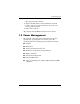
Product Description 3. Wait approximately 5 minutes. 4. Replace the RTC battery and reassemble the notebook. 5. Connect AC power to the notebook. Do not reinsert any battery packs at this time. 6. Turn on the notebook. All passwords and all CMOS settings have been cleared. 1.3 Power Management The notebook comes with power management features that extend battery operating time and conserve power.
Product Description 1.4 External Components The external components on the front of the notebook are shown below and described in Table 1-1. Front Components Table 1-1 Front Components Item Component Function 1 Wireless light On: An integrated wireless device, such as a wireless LAN device and/or a Bluetooth® device, is turned on. 2 Power/standby light Green: The notebook is on. Blinking green: The notebook is in standby mode. Off: The notebook is off or in hibernation.
Product Description Table 1-1 Front Components (Continued) Item Component Function 3 Battery light Amber: A battery pack is charging. Green: A battery pack is close to full charge capacity. Blinking amber: A battery pack that is the only available power source has reached a low-battery condition. When the battery reaches a critical low-battery condition, the battery light begins blinking more quickly.
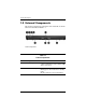
Product Description The external components on the right side of the notebook are shown below and described in Table 1-2.
Product Description Table 1-2 Right-Side Components Item Component Function 1 Optical drive Holds an optical disc. 2 RJ-11 (modem) jack Connects a modem cable.
Product Description The external components on the left side of the notebook are shown below and described in Table 1-3. Left-Side Components Table 1-3 Left-Side Components Item Component Function 1 Vent Enables airflow to cool internal components. Ä 2 1–10 To prevent overheating, do not obstruct vents. Using the notebook on a soft surface, such as a pillow, blanket, rug, or thick clothing, may block airflow. External monitor port Connects an external monitor.
Product Description Table 1-3 Left-Side Components (Continued) Item Component Function 3 1394 port Connects an optional IEEE 1394 device, such as a camcorder. 4 USB ports (2) Connect USB 1.1- and 2.0-compliant devices to the notebook using a standard USB cable, or connect an optional External MultiBay II to the notebook. The MultiBay II must also be connected to an external power source. 5 Audio-in (microphone) jack Connects an optional stereo or monaural microphone.
Product Description The external components on the rear panel of the notebook are shown below and described in Table 1-4.
Product Description Table 1-4 Rear Panel Components Item Component Function 1 Security cable slot Attaches an optional security cable to the notebook. Ä Security solutions are designed to act as deterrents. These deterrents may not prevent a product from being mishandled or stolen. 2 Battery bay Holds a battery pack. 3 Power connector Connects an AC adapter or an optional combination power adapter. 4 RJ-45 (network) jack Connects a network cable. 5 USB port Connects USB 1.1- and 2.
Product Description The standard keyboard components of the notebook are shown below and described in Table 1-5. Standard Keyboard Components Table 1-5 Standard Keyboard Components Item Component Function 1 Function keys Execute frequently used system functions when pressed in combination with the fn key. 2 caps lock key Enables caps lock and turns on the caps lock light. 3 fn key Executes frequently used system functions when pressed in combination with a function key or the esc key.
Product Description Table 1-5 Standard Keyboard Components (Continued) Item Component Function 4 Windows logo key Displays the Microsoft Windows Start menu. 5 Windows applications key Displays a shortcut menu for items beneath the pointer. 6 Arrow keys Moves the cursor around the screen. 7 Keypad keys Can be used like the keys on an external numeric keypad. 8 num lock key Enables numeric lock, turns on the embedded numeric keypad, and turns on the num lock light.
Product Description The notebook top components are shown below and described in Table 1-6. Top Components Table 1-6 Top Components Item Component Function 1 Display lid switch Puts the notebook in standby if the display is closed while the notebook is turned on. 2 Power/standby button When the notebook is: Off, press the button to turn on the notebook. In standby, briefly press the button to exit standby. In hibernation, briefly press the button to exit hibernation.
Product Description Table 1-6 Top Components (Continued) Item Component Function 3 Info Center button (HP Compaq nx6125 models only) Launches Info Center, which enables you to quickly open the following software solutions: Altiris Local Recovery, Contact HP, Help and Support, Options Demo, ProtectTools Security Manager, Software Setup, System Information, and Wireless Assistant. 4 Wireless button Turns the wireless functionality on or off, but does not create a wireless connection.
Product Description The notebook TouchPad components are shown below and described in Table 1-7.
Product Description Table 1-7 TouchPad Components Item Component Function 1 TouchPad Moves the pointer and selects or activates items on the screen. Can be set to perform other mouse functions, such as scrolling, selecting, and double-clicking. 2 Left and right TouchPad buttons Function like the left and right buttons on an external mouse. 3 Fingerprint reader HP Compaq nx6125 models only) Allows a fingerprint logon to Windows instead of using a password.
Product Description The external components on the bottom of the notebook are shown below and described in Table 1-8. Bottom Components Table 1-8 Bottom Components Item Component Function 1 Primary battery bay Holds the primary battery pack. 2 Primary battery locking latch Secures the primary battery pack into the battery bay. 3 Docking connector (HP Compaq nx6125 models only) Connects the notebook to an optional HP Advanced Docking Station or HP Docking Station.
Product Description Table 1-8 Bottom Components (Continued) Item Component Function 5 Memory module compartment Contains the memory module slots. 6 Hard drive bay Holds the hard drive. 7 Primary battery release latch Releases the primary battery pack from the battery bay.
Product Description 1.5 Design Overview This section presents a design overview of key parts and features of the notebook. Refer to Chapter 4, “Illustrated Parts Catalog,” to identify replacement parts, and Chapter 6, “Removal and Replacement Procedures,” for disassembly steps.
2 Troubleshooting Å WARNING: Only authorized technicians trained by HP should repair this equipment. All troubleshooting and repair procedures are detailed to allow only subassembly-/module-level repair. Because of the complexity of the individual boards and subassemblies, do not attempt to make repairs at the component level or modifications to any printed wiring board. Improper repairs can create a safety hazard.
Troubleshooting Accessing Computer Setup The information and settings in Computer Setup are accessed from the File, Security, Tools, and Advanced menus. 1. Open Computer Setup by turning on or restarting the notebook. Press f10 while the F10 = Based Setup message is displayed in the lower-left corner of the screen. ❏ To change the language, press f2. ❏ To view navigation information, press f1. ❏ To return to the Computer Setup menu, press esc. 2. Select the File, Security, Tools, or Advanced menu. 3.
Troubleshooting 4. To confirm the restoration, press f10. 5. Select File > Save changes and exit, and then follow the instructions on the screen. When the computer restarts, the factory settings are restored, and any identification information you have entered is saved. Selecting from the File Menu Table 2-1 File Menu Select To Do This System Information ■ View identification information about the notebook and any battery packs in the system.
Troubleshooting Selecting from the Security Menu Table 2-2 Security Menu Select To Do This Administrator password Enter, change, or delete an HP Administrator password. Power-on password Enter, change, or delete a power-on password. Password options ■ Enable/Disable stringent security. ■ Enable/Disable required password on restart. DriveLock passwords Enable/disable DriveLock; change a DriveLock user or master password.
Troubleshooting Selecting from the Tools Menu Table 2-3 Tools Menu Select To Do This HDD Self Test options Run a quick or comprehensive self-test on any hard drive in the system. Battery Information View information about any battery packs in the notebook. Memory Check ■ Run a self-test on memory modules in the notebook. ■ View information about memory modules installed in the notebook.
Troubleshooting Selecting from the Advanced Menu Table 2-4 Advanced Menu Select To Do This Language (or press f2) Change the Computer Setup language. Boot options ■ Enable/Disable MultiBoot, which sets a startup sequence that can include most bootable devices and media in the system. ■ Set the boot order. Device options ■ Swap the functions of the fn key and left ctrl key. ■ Enable/Disable multiple pointing devices at startup.
Troubleshooting 2.2 Troubleshooting Flowcharts Table 2-5 Troubleshooting Flowcharts Overview Flowchart Description 2.1 “Flowchart 2.1—Initial Troubleshooting” 2.2 “Flowchart 2.2—No Power, Part 1” 2.3 “Flowchart 2.3—No Power, Part 2” 2.4 “Flowchart 2.4—No Power, Part 3” 2.5 “Flowchart 2.5—No Power, Part 4” 2.6 “Flowchart 2.6—No Video, Part 1” 2.7 “Flowchart 2.7—No Video, Part 2” 2.8 “Flowchart 2.8—Nonfunctioning Docking Device (if applicable)” 2.9 “Flowchart 2.
Troubleshooting Table 2-5 Troubleshooting Flowcharts Overview (Continued) Flowchart Description 2.14 “Flowchart 2.14—No OS Loading, Optical Drive” 2.15 “Flowchart 2.15—No Audio, Part 1” 2.16 “Flowchart 2.16—No Audio, Part 2” 2.17 “Flowchart 2.17—Nonfunctioning Device” 2.18 “Flowchart 2.18—Nonfunctioning Keyboard” 2.19 “Flowchart 2.19—Nonfunctioning Pointing Device” 2.20 “Flowchart 2.
Troubleshooting Flowchart 2.1—Initial Troubleshooting Begin troubleshooting. N Go to Is there power? “Flowchart 2.2—No Power, Part 1.” Y N Check LED board, speaker connections. Beeps, LEDs, or error messages? N Y Go to All drives working? N Go to Is there video? (no boot) Y “Flowchart 2.6—No Video, Part 1.” N Keyboard/ pointing device working? Y N Go to Is the OS loading? N Go to Is there sound? Y “Flowchart 2.9—No Operating System (OS) Loading.” Y “Flowchart 2.15—No Audio, Part 1.
Troubleshooting Flowchart 2.2—No Power, Part 1 No power (power LED is off). Remove from docking device (if applicable). N N Power up on battery power? Go to Power up on battery power? Reset power.* “Flowchart 2.3—No Power, Part 2.” Y Y N N Power up on AC power? Power up on AC power? Reset power.* Go to “Flowchart 2.4—No Power, Part 3.” Y Y Y Power up in docking device? Done *NOTES N 1. Reset the power cables in the docking device and at the AC outlet. 2.
Troubleshooting Flowchart 2.3—No Power, Part 2 Continued from “Flowchart 2.2—No Power, Part 1.” Visually check for debris in battery socket and clean if necessary. Y Power on? Done N Check battery by recharging it, moving it to another notebook, or replacing it. N Replace power supply (if applicable). Power on? Y N Go to Done Power on? “Flowchart 2.4—No Power, Part 3.
Troubleshooting Flowchart 2.4—No Power, Part 3 Continued from “Flowchart 2.3—No Power, Part 2.” Plug directly into AC outlet. Y Power LED on? Done N Reseat AC adapter in notebook and at power source. Y Power on? Done N External N Try different outlet. Power outlet active? Y Internal or external AC adapter? Replace external AC adapter. N Internal Go to “Flowchart 2.5—No Power, Part 4.” Replace power cord.
Troubleshooting Flowchart 2.5—No Power, Part 4 Continued from “Flowchart 2.4—No Power, Part 3.” Open notebook. Y Loose or damaged parts? N Reseat loose components and boards and replace damaged items. Close notebook and retest. N Power on? Replace the following items (if applicable). Check notebook operation after each replacement: 1. Internal DC-DC converter* 2. Internal AC adapter 3. Processor board* 4.
Troubleshooting Flowchart 2.6—No Video, Part 1 No video. Docking Device Go to Stand-alone or docking device? *NOTE: To change from internal to external display, use the hotkey combination. “Flowchart 2.7—No Video, Part 2.” Stand-alone Internal or external display*? Y Adjust brightness. A Adjust brightness. Press lid switch to ensure operation. Y Video OK? Done N Internal External Video OK? Y Done N Video OK? Done N Replace the following one at a time. Test after each replacement. 1.
Troubleshooting Flowchart 2.7—No Video, Part 2 Continued from “Flowchart 2.6—No Video, Part 1.” Remove notebook from docking device, if connected. Adjust display brightness. Check brightness of external monitor. N Y Go to “A” in “Flowchart 2.6—No Video, Part 1.” Video OK? Y Video OK? Done N Check that notebook is properly seated in docking device, for bent pins on cable, and for monitor connection. Try another external monitor.
Troubleshooting Flowchart 2.8—Nonfunctioning Docking Device (if applicable) Nonfunctioning docking device. Reset power cord in docking device and power outlet. Check voltage setting on docking device. Reinstall notebook into docking device. Y Reset monitor cable connector at docking device. Docking device operating? N Y Docking device operating? N Remove notebook, reset all internal parts, and replace any damaged items in docking device.
Troubleshooting Flowchart 2.9—No Operating System (OS) Loading No OS loading.* Reset power cord in docking device and power outlet. No OS loading from hard drive, go to “Flowchart 2.10—No OS Loading, Hard Drive, Part 1.” No OS loading from diskette drive, go to “Flowchart 2.13—No OS Loading, Diskette Drive.” No OS loading from CD-ROM or DVD-ROM drive, go to “Flowchart 2.14—No OS Loading, Optical Drive.” No OS loading from network, go to “Flowchart 2.20—No Network/Modem Connection.
Troubleshooting Flowchart 2.10—No OS Loading, Hard Drive, Part 1 OS not loading from hard drive. Y Nonsystem disk message? N Go to “Flowchart 2.11—No OS Loading, Hard Drive, Part 2.” Reseat external hard drive. Y OS loading? Done N N Boot from CD? N Y Boot from diskette? Check the Setup utility for correct booting order. Y Change boot priority through the Setup utility and reboot. N Boot from hard drive? N Y Boot from hard drive? Done Y 2–18 Go to “Flowchart 2.
Troubleshooting Flowchart 2.11—No OS Loading, Hard Drive, Part 2 Continued from “Flowchart 2.10—No OS Loading, Hard Drive, Part 1.” Reseat hard drive. N 1. Replace hard drive. 2. Replace system board. CD or diskette in drive? Y Hard drive accessible? Y Done N Remove diskette and reboot. Run FDISK. Y Boot from hard drive? N Done N Hard drive partitioned? Y N Y N Go to “Flowchart 2.13—No OS Loading, Diskette Drive.
Troubleshooting Flowchart 2.12—No OS Loading, Hard Drive, Part 3 Continued from “Flowchart 2.11—No OS Loading, Hard Drive, Part 2.” N System files on hard drive? Install OS and reboot. Y Y Y Virus on hard drive? OS loading from hard drive? Clean virus. N Done N Y Run SCANDISK and check for bad sectors. Diagnostics on diskette? Replace hard drive. N N Can bad sectors be fixed? Run diagnostics and follow recommendations. Replace hard drive. Y N Boot from hard drive? Fix bad sectors.
Troubleshooting Flowchart 2.13—No OS Loading, Diskette Drive Y OS not loading from diskette drive. Reseat diskette drive. OS loading? Done N Y N Bootable diskette in drive? Nonsystem disk message? N Y N Check diskette for system files. Try different diskette. Go to Boot from another device? “Flowchart 2.17—Nonfunctioning Device.” Y Y N Diskette drive enabled in the Setup utility? 1. Replace diskette drive. 2. Replace system board. Nonsystem disk error? Enable drive and cold boot notebook.
Troubleshooting Flowchart 2.14—No OS Loading, Optical Drive Y No OS loading from CD-ROM or DVD-ROM drive. N Install bootable disc and reboot notebook. Bootable disc in drive? Disc in drive? Y N Install bootable disc. Try another bootable disc. Y Boots from CD or DVD? Done N Y Boots from CD or DVD? Reseat drive. Done N N Booting from another device? Y Y Booting order correct? N Go to “Flowchart 2.17—Nonfunctioning Device.” Reset the notebook. Refer to Go to Section 1.
Troubleshooting Flowchart 2.15—No Audio, Part 1 Y Turn up audio internally or externally. No audio. Audio? Done N N Y Notebook in docking device (if applicable)? Go to Internal audio? Undock N “Flowchart 2.16—No Audio, Part 2.” Y Replace the following docking device components one at a time, as applicable. Check audio status after each change. Go to “Flowchart 2.16—No Audio, Part 2.” 1. Reset docking device audio cable. 2. Replace audio cable. 3. Replace speaker. 4.
Troubleshooting Flowchart 2.16—No Audio, Part 2 Continued from “Flowchart 2.15—No Audio, Part 1.” N Audio driver in OS configured? Reload audio drivers. Y N Correct drivers for application? Load drivers and set configuration in OS. Y Connect to external speaker. N Audio? Y Replace audio board and speaker connections in notebook (if applicable). Y Audio? Done N 1. Replace internal speakers. 2. Replace audio board (if applicable). 3. Replace system board.
Troubleshooting Flowchart 2.17—Nonfunctioning Device Nonfunctioning device. Reseat device. Unplug the nonfunctioning device from the notebook and inspect cables and plugs for bent or broken pins or other damage. Y Clear CMOS. Fix or replace broken item. Any physical device detected? N Reattach device. Close notebook, plug in power, and reboot. Go to “Flowchart 2.9—No Operating System (OS) Loading.” Replace hard drive. N Device boots properly? N Replace NIC.
Troubleshooting Flowchart 2.18—Nonfunctioning Keyboard Keyboard not operating properly. Connect notebook to good external keyboard. N External device works? Replace system board. Y Reseat internal keyboard connector (if applicable). N Replace internal keyboard or cable. OK? Y Y Done OK? Done N Replace system board.
Troubleshooting Flowchart 2.19—Nonfunctioning Pointing Device Pointing device not operating properly. Connect notebook to good external pointing device. N Replace system board. External device works? Y Reseat internal pointing device connector (if applicable). N Replace internal pointing device or cable. OK? Y Y Done OK? Done N Replace system board.
Troubleshooting Flowchart 2.20—No Network/Modem Connection No network or modem connection. N Network or modem jack active? Replace jack or have jack activated. Y Y Connect to nondigital line. Digital line? N Y N NIC/modem configured in OS? Reload drivers and reconfigure. Done OK? N Y Disconnect all power from the notebook and open. Replace NIC/modem (if applicable). Y Reseat NIC/modem (if applicable). OK? Done N Replace system board.
3 Software Update and Recovery 3.1 Software Updates To stay current with the newest technology and maintain optimal performance, install the latest versions of HP software on your computer as they become available. To update HP software: 1. Identify your computer model, product category, and series or family. Prepare for a system ROM update by identifying the ROM version currently installed on the computer. For more information, refer to “Accessing Computer Information.
Software Update and Recovery Accessing Computer Information Before you access the updates for your computer, collect the following information: ■ The product category is Notebook. ■ The product family name and series number are printed on the display bezel. ■ Model information is provided on the serial number label on the bottom of the computer.
Software Update and Recovery Obtaining the Support Software CD The Support Software CD provides HP software updates and installation instructions. The CD includes device drivers, ROM updates, and utilities. To purchase the current Support Software CD or a subscription that provides both the current version and future versions of the CD, visit the HP Web site at http://www.hp.com. Software Updates and the HP Web Site Most software on the HP Web site is packaged in compressed files called SoftPaqs.
Software Update and Recovery To download a ROM update: 1. Access the page on the HP Web site that provides software for your computer: ❏ Select Start > Help and Support, and then click a software update link. – or – ❏ Visit the HP Web site at http://www.hp.com/support. 2. Follow the instructions on the screen to identify your computer and access the ROM update you want to download. 3. At the download area: a. Identify the ROM update that is later than the ROM version currently installed on your computer.
Software Update and Recovery ROM installation procedures vary. Follow any instructions that are displayed on the screen after the download is complete. If no instructions are displayed: 1. Open Windows Explorer by selecting Start > All Programs > Accessories > Windows Explorer. 2. In the left pane of the Windows Explorer window: a. Click My Computer and then your hard drive designation. (The hard drive designation is typically Local Disk C.) b. Open the folder on your hard drive that contains the update.
Software Update and Recovery 2. Follow the instructions on the screen to find the software you want to update. 3. At the download area, select the software you want and follow the download instructions on the Web page. a note of the path to the location on your hard drive ✎ Make where the ROM package will be downloaded. You may need to access the ROM package after it has been downloaded. 4.
Software Update and Recovery Safeguarding Your Data Software or devices added to the computer can cause your system to become unstable. To safeguard your documents, store personal files in the My Documents folder and periodically create a backup copy of the My Documents folder. Altiris Local Recovery Altiris Local Recovery is a preloaded application that protects the files on your computer by storing copies of files, called snapshots.
Software Update and Recovery Using System Restore Points System Restore is an operating system feature that allows you to reverse undesirable changes to your computer by restoring the computer to an earlier state, called a restore point. A restore point is a “snapshot” of your software, drivers, and operating system files at a particular time.
Software Update and Recovery Restoring to a Restore Point To restore the computer to a previous date and time when it was functioning optimally: 1. Select Start > Help and Support. 2. Click System Restore. The System Restore window opens. 3. Click Restore my computer to an earlier time, and then click Next. 4. Follow the on-screen instructions. Reinstalling Applications Applications preinstalled or preloaded on your computer can be reinstalled by using the Recovery disc or a third-party software disc.
Software Update and Recovery Reinstalling Applications from the Hard Drive To reinstall a preloaded application or utility from your hard drive: 1. Select Start > All Programs > Software Setup, and then follow the instructions on the screen. 2. When you are prompted to select the software you want to reinstall, select or clear the appropriate check boxes. Reinstalling Applications from Discs To reinstall applications from discs: 1. Insert the disc into the optical drive.
Software Update and Recovery 1. Connect the computer to external power through the AC adapter and turn on the computer. 2. Immediately insert the Operating System disc into the computer. 3. Press and hold the power/standby button for at least 5 seconds to turn off the computer. 4. Press the power/standby button again to turn on the computer. 5. When prompted, press any key to start from the disc. After a few minutes, you may need to select your language, and then the Setup Wizard opens.
Software Update and Recovery Reinstalling the Operating System Ä CAUTION: To protect your personal data and the software installed on the computer, back up your data before reinstalling the operating system. See the Windows online Help utility to learn more about backing up your files. Select Start > Help and Support. Then type “backup” in the Search box. the reinstallation, you may be prompted for your ✎ During Product Key.
Software Update and Recovery 4. Press the power/standby button again to turn on the computer. 5. When prompted, press any key to start from the disc. After a few minutes, you may need to select your language, and then the Setup Wizard opens. 6. Press enter to continue. A licensing agreement page is displayed. 7. Press f8 to accept the agreement and continue. The “Setup” page is displayed. 8. Press esc to continue installing a new copy of the operating system instead of repairing it. 9.
Software Update and Recovery Reinstalling Device Drivers and Other Software After the operating system installation process is complete, you must reinstall drivers. To reinstall drivers, use the Recovery disc included with the computer: 1. While running Windows, insert the Recovery disc into the optical drive. 2. If you do not have autorun enabled: a. Select Start > Run. b. Then type D:\SWSETUP\APPINSTL\SETUP.EXE where D indicates the optical drive. 3.
4 Illustrated Parts Catalog This chapter provides an illustrated parts breakdown and a reference for spare part numbers. 4.1 Serial Number Location When ordering parts or requesting information, provide the notebook serial number and model number located on the bottom of the notebook.
Illustrated Parts Catalog 4.
Illustrated Parts Catalog Table 4-1 Spare Parts: Notebook Major Components Item Description Spare Part Number 1 Display assemblies (include wireless antenna boards and cables) 15.0-inch, SXGA+WVA, TFT 15.
Illustrated Parts Catalog Notebook Major Components 4–4 Maintenance and Service Guide
Illustrated Parts Catalog Table 4-1 Spare Parts: Notebook Major Components (Continued) Item Description 4 Keyboards Brazil Czech Republic Denmark Europe France French Canada Germany Greece Hungary Iceland Israel Italy Japan Korea Latin America The Netherlands Norway 5 Spare Part Number 393568-201 393568-221 393568-081 393568-021 393568-051 393568-121 393568-041 393568-151 393568-211 393568-DD1 393568-BB1 393568-061 393568-291 393568-AD1 393568-161 393568-331 393568-091 Heat sink (includes thermal pa
Illustrated Parts Catalog Notebook Major Components 4–6 Maintenance and Service Guide
Illustrated Parts Catalog Table 4-1 Spare Parts: Notebook Major Components (Continued) Item Description Spare Part Number 6 Processors (include thermal paste) AMD Turion 64 ML-40 2.2-GHz AMD Turion 64 ML-37 2.0-GHz AMD Turion 64 ML-34 1.8-GHz AMD Turion 64 ML-32 1.8-GHz AMD Turion 64 ML-30 1.6-GHz AMD Turion 64 ML-28 1.6-GHz Mobile AMD Sempron 3100+ (1.80-GHz) Mobile AMD Sempron 3000+ (1.80-GHz) Mobile AMD Sempron 2800+ (1.
Illustrated Parts Catalog Notebook Major Components 4–8 Maintenance and Service Guide
Illustrated Parts Catalog Table 4-1 Spare Parts: Notebook Major Components (Continued) Item Description Spare Part Number 12 RTC battery 393588-001 13 Speaker 393563-001 14 System boards For use on HP Compaq nx6125 models For use on HP Compaq nx6115 models 393569-001 393570-001 15 Optical drives (include bezel) 24X Max CD-ROM drive 8X Max DVD-ROM drive 24X Max DVD/CD-RW Combo Drive 8X Max DVD±RW and CD-RW Combo Drive DVD±RW and CD-RW Combo Drive, Dual Layer Drive 16 17 393537-001 393538-001
Illustrated Parts Catalog Notebook Major Components 4–10 Maintenance and Service Guide
Illustrated Parts Catalog Table 4-1 Spare Parts: Notebook Major Components (Continued) Spare Part Number Item Description 18 Memory modules (333-MHz, DDR, PC2700) 19a 19b 20 1024 MB 512 MB 256 MB 393573-001 393572-001 393571-001 Miscellaneous Plastics Kit 393593-001 Includes: Memory module compartment cover (includes 2 captive screws) Hard drive cover (includes 2 captive screws) Not illustrated: Notebook feet PC Card slot space saver ExpressCard slot space saver Hard drives (include frame and co
Illustrated Parts Catalog 4.
Illustrated Parts Catalog 4.
Illustrated Parts Catalog 4.
Illustrated Parts Catalog Table 4-4 Mass Storage Devices Spare Part Number Information Spare Part Number Item Description 1 Hard drives (include frame and connector) 5400-rpm 80-GB 60-GB 40-GB 2 393548-001 393546-001 393544-001 4200-rpm 80-GB 60-GB 40-GB 30-GB 393547-001 393545-001 393543-001 393542-001 Optical drives (include bezel) 24X Max CD-ROM drive 8X Max DVD-ROM drive 24X Max DVD/CD-RW Combo Drive 8X Max DVD±RW and CD-RW Combo Drive DVD±RW and CD-RW Combo, Dual Layer Drive Maintenance and
Illustrated Parts Catalog 4.6 Miscellaneous (Not Illustrated) Table 4-5 Miscellaneous (Not Illustrated) Spare Part Information Description Spare Part Number Label Kit 393592-001 Adjustable notebook stand 372420-001 HP Advanced Docking Station 374504-001 HP Docking Station 374803-001 65 watt AC adapter 338136-001 Screw Kit (includes the following screws; refer to Appendix C, “Screw Listing,” for more information on specifications and usage 393596-001 ■ ■ ■ ■ Phillips PM2.5×6.
Illustrated Parts Catalog Table 4-5 Miscellaneous (Not Illustrated) Spare Part Information (Continued) Description Spare Part Number Power cords For use in: Australia and New Zealand 350188-011 Belgium, Europe, Finland, France, Germany, Greece, the Netherlands, Norway, Portugal, Spain, and Sweden 350188-021 Canada, French Canada, Latin America, Taiwan, Thailand, and the United States 350188-001 Denmark 350188-081 Hong Kong and the United Kingdom 350188-031 Israel 350188-BB1 Japan 350188-291
Illustrated Parts Catalog 4.
Illustrated Parts Catalog Table 4-6 Sequential Part Number Listing (Continued) Spare Part Number Description 377407-291 802.11a/b/g WLAN mini PCI communications card for use in Japan 385894-001 6-cell, 4.8-AHr battery pack 385895-001 6-cell, 4.4-AHr battery pack 392557-001 802.11b/g WLAN mini PCI communications card for use in the United States 392557-002 802.11b/g WLAN mini PCI communications card for use in the rest of the world 392557-291 802.
Illustrated Parts Catalog Table 4-6 Sequential Part Number Listing (Continued) Spare Part Number Description 393548-001 5400-rpm, 80-GB hard drive (includes frame and connector) 393549-001 6-cell, 4.4-AHr battery pack 393551-001 15.0-inch, XGA, TFT display assembly (include wireless antenna boards and cables) 393552-001 15.0-inch, SXGA+WVA, TFT display assembly (include wireless antenna boards and cables) 393554-001 Display bracket with hinges for use on models with 14.
Illustrated Parts Catalog Table 4-6 Sequential Part Number Listing (Continued) Spare Part Number Description 393567-001 Heat sink (includes thermal paste) 393568-001 Keyboard for use in the United States 393568-021 Keyboard for use in Europe 393568-031 Keyboard for use in the United Kingdom 393568-041 Keyboard for use in Germany 393568-051 Keyboard for use in France 393568-061 Keyboard for use in Italy 393568-071 Keyboard for use in Spain 393568-081 Keyboard for use in Denmark 393568-09
Illustrated Parts Catalog Table 4-6 Sequential Part Number Listing (Continued) Spare Part Number Description 393568-221 Keyboard for use in Czech Republic 393568-231 Keyboard for use in Slovakia 393568-241 Keyboard for use in Poland 393568-251 Keyboard for use in Russia 393568-281 Keyboard for use in Thailand 393568-291 Keyboard for use in Japan 393568-331 Keyboard for use in the Netherlands 393568-AA1 Keyboard for use in the People’s Republic of China 393568-AB1 Keyboard for use in Taiw
Illustrated Parts Catalog Table 4-6 Sequential Part Number Listing (Continued) Spare Part Number Description 393577-001 AMD Turion 64 ML-34 1.8-GHz processor (includes thermal paste) 393578-001 AMD Turion 64 ML-37 2.0-GHz processor (includes thermal paste) 393579-001 AMD Turion 64 ML-40 2.2-GHz processor (includes thermal paste) 393580-001 Mobile AMD Sempron 3100+ (1.60-GHz) processor (includes thermal paste) 393581-001 Mobile AMD Sempron 3100+ (1.
Illustrated Parts Catalog Table 4-6 Sequential Part Number Listing (Continued) Spare Part Number Description 393590-001 PC Card assembly without Smart Card reader, for use on HP Compaq nx6125 models 393591-001 PC Card assembly without Smart Card reader, for use on HP Compaq nx6115 models 393592-001 Label Kit 393593-001 Miscellaneous Plastics Kit 393594-001 Miscellaneous Cable Kit 393595-001 Bracket Kit 393596-001 Screw Kit 393597-001 Fan 395742-001 AMD Turion 64 ML-28 1.
5 Removal and Replacement Preliminaries This chapter provides essential information for proper and safe removal and replacement service. 5.
Removal and Replacement Preliminaries 5.2 Service Considerations The following sections include some of the considerations that you should keep in mind during disassembly and assembly procedures. you remove each subassembly from the notebook, place ✎ As the subassembly (and all accompanying screws) away from the work area to prevent damage. Plastic Parts Using excessive force during disassembly and reassembly can damage plastic parts. Use care when handling the plastic parts.
Removal and Replacement Preliminaries 5.3 Preventing Damage to Removable Drives Removable drives are fragile components that must be handled with care. To prevent damage to the notebook, damage to a removable drive, or loss of information, observe the following precautions: ■ Before removing or inserting a hard drive, shut down the notebook. If you are unsure whether the notebook is off or in hibernation, turn the notebook on, and then shut it down through the operating system.
Removal and Replacement Preliminaries 5.4 Preventing Electrostatic Damage Many electronic components are sensitive to electrostatic discharge (ESD). Circuitry design and structure determine the degree of sensitivity. Networks built into many integrated circuits provide some protection, but in many cases, the discharge contains enough power to alter device parameters or melt silicon junctions.
Removal and Replacement Preliminaries 5.5 Packaging and Transporting Precautions Use the following grounding precautions when packaging and transporting equipment: ■ To avoid hand contact, transport products in static-safe containers, such as tubes, bags, or boxes. ■ Protect all electrostatic-sensitive parts and assemblies with conductive or approved containers or packaging. ■ Keep electrostatic-sensitive parts in their containers until the parts arrive at static-free workstations.
Removal and Replacement Preliminaries 5.6 Workstation Precautions Use the following grounding precautions at workstations: ■ Cover the workstation with approved static-shielding material (refer to Table 4-2, “Static-Shielding Materials”). ■ Use a wrist strap connected to a properly grounded work surface and use properly grounded tools and equipment. ■ Use conductive field service tools, such as cutters, screwdrivers, and vacuums.
Removal and Replacement Preliminaries 5.7 Grounding Equipment and Methods Grounding equipment must include either a wrist strap or a foot strap at a grounded workstation. ■ When seated, wear a wrist strap connected to a grounded system. Wrist straps are flexible straps with a minimum of one megohm ±10% resistance in the ground cords. To provide proper ground, wear a strap snugly against the skin at all times. On grounded mats with banana-plug connectors, use alligator clips to connect a wrist strap.
Removal and Replacement Preliminaries Table 5-1 shows how humidity affects the electrostatic voltage levels generated by different activities.
6 Removal and Replacement Procedures This chapter provides removal and replacement procedures. There are 60 screws and nuts, in 8 different sizes, that may have to be removed, replaced, or loosened when servicing the notebook. Make special note of each screw and screw lock size and location during removal and replacement. Refer to Appendix C, “Screw Listing,” for detailed information on screw and nut sizes, locations, and usage. 6.
Removal and Replacement Procedures 6.2 Disassembly Sequence Chart Use the chart below to determine the section number to be referenced when removing notebook components. Disassembly Sequence Chart Section Description 6.3 Preparing the Notebook for Disassembly Battery pack # of Screws Removed 0 6.4 Hard Drive 2 loosened to remove the hard drive cover 4 to disassemble the hard drive 6.5 Notebook Feet 0 6.6 Bluetooth Board 1 6.
Removal and Replacement Procedures Disassembly Sequence Chart (Continued) Section Description # of Screws Removed 6.16 Mini PCI Communications Card 0 Å To prevent an unresponsive system and the display of a warning message, install only a Mini PCI device authorized for use in your notebook by the governmental agency that regulates wireless devices in your country. If you install a device and then receive a warning message, remove the device to restore notebook functionality.
Removal and Replacement Procedures 6.3 Preparing the Notebook for Disassembly Before you begin any removal or installation procedures: 1. Shut down the notebook. If you are unsure whether the notebook is off or in hibernation, turn the computer on, and then shut it down through the operating system. 2. Disconnect all external devices connected to the notebook. 3. Disconnect the power cord. Battery Pack Spare Part Number Information 6-cell, 4.8-AHr 6-cell, 4.4-AHr 6-cell, 4.
Removal and Replacement Procedures b. Slide the battery pack lock latch 1 to the right. (The battery pack disengages from the notebook.) c. Slide and hold the battery pack release latch 2 to the right. d. Slide the battery pack forward 3 and remove it. Removing the Battery Pack Reverse the above procedure to install the battery pack.
Removal and Replacement Procedures 6.4 Hard Drive Hard Drive Spare Part Number Information 5400-rpm 80-GB 60-GB 40-GB 393548-001 393546-001 393544-001 4200-rpm 80-GB 60-GB 40-GB 30-GB 393547-001 393545-001 393543-001 393542-001 1. Prepare the notebook for disassembly (refer to Section 6.3). 2. Loosen the 2 Phillips PM2.5×6.0 screws 1 that secure the hard drive cover to the notebook. 3. Lift the right side of the hard drive cover and swing it to the left 2. 4. Remove the hard drive cover.
Removal and Replacement Procedures 5. Grasp the mylar tab 1 on the right side of the hard drive and slide the hard drive to the right 2 to disconnect it from the system board. 6. Remove the hard drive from the hard drive bay 3.
Removal and Replacement Procedures 7. Remove the 4 Phillips PM3.0×5.0 hard drive frame screws 1 from each side of the hard drive. 8. Lift the frame straight up 2 to remove if from the hard drive. Removing the Hard Drive Frame Reverse the above procedure to reassemble and install the hard drive.
Removal and Replacement Procedures 6.5 Notebook Feet The notebook feet are adhesive-backed rubber pads. The feet are included in the Miscellaneous Plastics Kit, spare part number 393593-001.
Removal and Replacement Procedures 6.6 Bluetooth Board Bluetooth Board Spare Part Number Information Broadcomm Bluetooth wireless board (includes Bluetooth board cable) 393566-001 1. Prepare the notebook for disassembly (refer to Section 6.3). 2. Remove the hard drive cover and hard drive (Section 6.4). 3. Position the notebook with the front toward you.
Removal and Replacement Procedures 4. Remove the Phillips PM1.5×3.0 screw 1 that secures the Bluetooth board to the notebook. 5. Slide the Bluetooth board forward 2 and out of the clip in the top cover. 6. Remove the Bluetooth board from the notebook 3. 7. Disconnect the Bluetooth board cable 4 from the board. Removing the Bluetooth Board Reverse the above procedure to install a Bluetooth board.
Removal and Replacement Procedures 6.7 Memory Module Memory Module Spare Part Number Information 1024 MB 512 MB 256 MB 393573-001 393572-001 393571-001 1. Prepare the notebook for disassembly (refer to Section 6.3). 2. Position the notebook with the rear panel toward you. 3. Loosen the 2 Phillips PM2.5×6.0 screws 1 that secure the memory module compartment cover to the notebook. 4. Lift the rear edge of the cover up and swing it toward you 2. 5. Remove the memory module compartment cover.
Removal and Replacement Procedures 6. Spread the retaining tabs 1 on each side of the memory module socket to release the memory module board. (The edge of the module opposite the socket rises away from the notebook.) 7. Slide the module away from the socket at an angle 2. 8. Remove the memory module board. modules are slotted 3 to prevent incorrect installation ✎ Memory into the memory module socket. Removing the Memory Module Reverse the above procedure to install a memory module.
Removal and Replacement Procedures 6.8 Optical Drive Optical Drive Spare Part Number Information 24X Max CD-ROM drive 8X Max DVD-ROM drive 24X Max DVD/CD-RW Combo Drive 8X Max DVD±RW and CD-RW Combo Drive DVD±RW and CD-RW Combo, Dual Layer Drive 393537-001 393538-001 393539-001 393540-001 393541-001 1. Prepare the notebook for disassembly (Section 6.3). 2. Remove the memory module compartment cover (Section 6.7). 3. Position the notebook with the right side toward you.
Removal and Replacement Procedures 4. Remove the Torx T8M2.5×9.0 screw 1 that secures the optical drive to the notebook. 5. Insert a thin tool, such as an unbent paper clip 2, into the media tray release hole and release the media tray. 6. Use the media tray to slide the optical drive out of the notebook 3. 7. Remove the optical drive. Removing the Optical Drive Reverse the above procedure to install an optical drive.
Removal and Replacement Procedures 6.9 Switch Cover Switch Cover Spare Part Number Information For use on HP Compaq nx6125 models For use on HP Compaq nx6115 models 393561-001 393562-001 1. Prepare the notebook for disassembly (Section 6.3). 2. Remove the 3 Torx T8M2.5×4.0 screws 1 and the Torx T8M2.5×9.0 screw 2 that secure the switch cover to the notebook.
Removal and Replacement Procedures 3. Turn the notebook display-side up with front toward you. 4. Open the notebook as far as possible. 5. Insert a flat blade screwdriver into the 2 notches in the switch cover (one behind the f1 and f2 keys 1, one behind the pause and insert keys 2) and lift up 3 until the front edge of the switch cover disengages from the notebook.
Removal and Replacement Procedures 6. Use a flat blade screwdriver to separate the left 1 and right hinge covers 2 from the notebook and release the switch cover.
Removal and Replacement Procedures 7. Disconnect the power button board cable from the system board. 8. Remove the switch cover. Removing the Switch Cover Reverse the above procedure to install the switch cover.
Removal and Replacement Procedures 6.10 Power Button Board Power Button Board Spare Part Number Information Power button board (includes power button board cable) 393583-001 1. Prepare the notebook for disassembly (Section 6.3). 2. Remove the switch cover (Section 6.9). 3. Turn the switch cover upside down with the hinge covers toward you.
Removal and Replacement Procedures 4. Remove the Torx T8M2.5×4.0 screw 1 that secures the power button board to the switch cover. 5. Remove the power button board 2. Removing the Power Button Board Reverse the above procedure to install the power button board.
Removal and Replacement Procedures 6.
Removal and Replacement Procedures 3. Remove the 4 Torx T8M2.5×4.0 screws that secure the keyboard to the notebook.
Removal and Replacement Procedures 4. Lift the rear edge of the keyboard up and swing it forward until it rests on the palm rest.
Removal and Replacement Procedures 5. Release the zero insertion force (ZIF) connector to which the keyboard cable is attached and disconnect the keyboard cable. Disconnecting the Keyboard Cable 6. Remove the keyboard. Reverse the above procedure to install the keyboard.
Removal and Replacement Procedures 6.12 Fan Fan Spare Part Number Information Fan 393597-001 1. Prepare the notebook for disassembly (Section 6.3). 2. Remove the switch cover (Section 6.9). 3. Remove the keyboard (Section 6.11). 4. Disconnect the fan cable 1 from the system board. 5. Remove the 3 Torx T8M2.5×7.0 screws 2 that secure the fan to the notebook. 6. Remove the fan 3. Removing the Fan Reverse the above procedure to install the fan.
Removal and Replacement Procedures 6.13 Heat Sink Heat Sink Spare Part Number Information Heat sink (includes thermal paste) 393567-001 1. Prepare the notebook for disassembly (Section 6.3) and then remove the following components: a. Switch cover (Section 6.9) b. Keyboard (Section 6.11) c. Fan (Section 6.
Removal and Replacement Procedures 2. Remove the 4 Torx T8M2.5×7.0 screws 1 that secure the heat sink to the notebook. 3. Lift the right side of the heat sink 2 to disengage it from the processor. 4. Slide the heat sink up and to the right 3 to remove it. to the adhesive quality of the thermal paste located ✎ Due between the heat sink and processor, it may be necessary to move the heat sink from side to side to detach the heat sink from the processor.
Removal and Replacement Procedures thermal paste should be thoroughly cleaned from the ✎ The surfaces of the heat sink 1 and processor 2 each time the heat sink is removed. Thermal paste should be reapplied to both surfaces before the heat sink is reinstalled. Thermal paste is included with all heat sink and processor spare part kits. Replacing the Thermal Paste Reverse the above procedure to install the heat sink.
Removal and Replacement Procedures 6.14 Processor Processor Spare Part Number Information AMD Turion 64 ML-40 2.2-GHz AMD Turion 64 ML-37 2.0-GHz AMD Turion 64 ML-34 1.8-GHz AMD Turion 64 ML-32 1.8-GHz AMD Turion 64 ML-30 1.6-GHz AMD Turion 64 ML-28 1.6-GHz 393579-001 393578-001 393577-001 395742-001 395743-001 395744-001 Mobile AMD Sempron 3100+ (1.80-GHz) Mobile AMD Sempron 3000+ (1.80-GHz) Mobile AMD Sempron 2800+ (1.60-GHz) 393582-001 393581-001 393580-001 1.
Removal and Replacement Procedures 2. Slide the tip of the processor socket release arm toward the display 1 until it clears the notch 2 on the processor socket. 3. Swing the processor socket release arm to the left 3 as far as it will go. 4. Lift the processor straight up and remove it 4. gold triangle 5 on the processor should be aligned in the ✎ The front right corner when you install the processor. Removing the Processor Reverse the above procedure to install the processor.
Removal and Replacement Procedures 6.15 Button Board Button Board Spare Part Number Information For use on HP Compaq nx6125 models For use on HP Compaq nx6115 models 393584-001 393585-001 1. Prepare the notebook for disassembly (Section 6.3). 2. Remove the switch cover (Section 6.9). 3. Remove the keyboard (Section 6.11).
Removal and Replacement Procedures 4. Release the ZIF connector to which the LED board cable is attached and disconnect the cable 1. 5. Remove the Torx T8M2.5×4.0 screw 2 that secures the LED board to the notebook. 6. Remove the LED board 3. Removing the LED Board Reverse the above procedure to install the LED board.
Removal and Replacement Procedures 6.16 Mini PCI Communications Card Mini PCI Communications Card Spare Part Number Information 802.11a/b/g WLAN card for use in most of the world 802.11a/b/g WLAN card for use in the rest of the world 802.11a/b/g WLAN card for use in Japan 377407-001 377407-002 377407-291 802.11b/g WLAN card for use in the United States 802.11b/g WLAN card for use in the rest of the world 802.11b/g WLAN card for use in Japan 392557-001 392557-002 392557-291 1.
Removal and Replacement Procedures 4. Disconnect the auxiliary and main 1 antenna cables from the Mini PCI communications card. disconnecting the antenna cables, make note of which ✎ Before cable is attached to which antenna clip on the Mini PCI communications card. 5. Spread the 2 retaining tabs 2 on each side of the Mini PCI socket to release the Mini PCI communications card. (The edge of the card opposite the socket rises away from the notebook.) 6.
Removal and Replacement Procedures 6.17 Display Assembly Display Assembly Spare Part Number Information 15.0-inch, SXGA+WVA, TFT 15.0-inch, XGA, TFT 393552-001 393551-001 1. Prepare the notebook for disassembly (Section 6.3) and then remove the following components: a. Switch cover (Section 6.9) b. Keyboard (Section 6.11) c. Button board (Section 6.15) 2. Turn the notebook upside down with the rear panel toward you.
Removal and Replacement Procedures 3. Remove the 2 Torx T8M2.5×9.0 screws 1 from the rear panel and the 2 Torx T8M2.5×9.0 screws 2 from the bottom of the notebook that secure the display assembly to the notebook.
Removal and Replacement Procedures 4. Turn the notebook display-side up with the front toward you. 5. Open the notebook as far as possible. 6. Disconnect the wireless antenna cables 1 from the Mini PCI communications board. 7. Remove the antenna cables from the clips 2 in the top cover. 8. Disconnect the microphone cable 3 from the system board. 9. Remove the microphone cable from the clips 4 in the top cover.
Removal and Replacement Procedures 10. Disconnect the display cable 1 from the system board. Ä CAUTION: Support the display assembly when removing the following screws. Failure to support the display assembly can result in damage to the display assembly and other notebook components. 11. Remove the 2 Torx T8M2.5×7.0 screws 2 that secure the display assembly to the notebook. 12. Lift the display assembly straight up and remove it 3.
Removal and Replacement Procedures 6.18 Top Cover Top Cover Spare Part Number Information For use on HP Compaq nx6125 models For use on HP Compaq nx6115 models 393559-001 393560-001 Fingerprint sensor 393586-001 1. Prepare the notebook for disassembly (Section 6.3) and then remove the following components: a. Optical drive (Section 6.8) b. Switch cover (Section 6.9) c. Fan (Section 6.12) d. Keyboard (Section 6.11) e. Button board (Section 6.15) f. Display assembly (Section 6.17) 2.
Removal and Replacement Procedures 3. Remove the 14 Torx T8M2.5×9.0 screws that secure the top cover to the notebook.
Removal and Replacement Procedures 4. Turn the notebook top-side up with the front toward you. 5. Release the ZIF connector to which the TouchPad cable 1 is connected and disconnect the TouchPad cable from the system board. 6. Disconnect the fingerprint reader cable 2 from the system board. 7. Remove the Torx T8M2.5×7.0 screw 3 that secures the top cover to the notebook.
Removal and Replacement Procedures 8. Lift up the rear edge of the top cover 1 until it disengages from the base enclosure. 9. Swing the top cover toward you 2 until the left and right sides of the top cover disengage from the base enclosure. 10. Lift up on the left 3 and right sides 4 of the top cover until the top cover disengages from the base enclosure. Releasing the Top Cover 11.
Removal and Replacement Procedures 6.19 TouchPad TouchPad Spare Part Number Information TouchPad (includes TouchPad cable) 393587-001 1. Prepare the notebook for disassembly (Section 6.3) and then remove the following components: a. Optical drive (Section 6.8) b. Switch cover (Section 6.9) c. Keyboard (Section 6.11) d. Button board (Section 6.15) e. Display assembly (Section 6.17) f. Top cover (Section 6.18) 2. Turn the top cover upside down with the front toward you.
Removal and Replacement Procedures 3. Remove the 2 Torx T8M2.5×4.0 screws 1 that secure the TouchPad to the notebook. 4. Slide the TouchPad frame back 2, then lift the back edge of the frame up and forward 3. 5. Remove the frame. Removing the TouchPad Frame 6. Remove the TouchPad. Removing the TouchPad Reverse the above procedure to install an TouchPad.
Removal and Replacement Procedures 6.20 RTC Battery RTC Battery Spare Part Number Information RTC battery 393588-001 1. Prepare the notebook for disassembly (Section 6.3) and then remove the following components: a. Optical drive (Section 6.8) b. Switch cover (Section 6.9) c. Keyboard (Section 6.11) d. Button board (Section 6.15) e. Display assembly (Section 6.17) f. Top cover (Section 6.
Removal and Replacement Procedures 2. Remove the RTC battery from the socket on the system board. Removing the RTC Battery Reverse the above procedure to install an RTC battery.
Removal and Replacement Procedures 6.21 Speaker Speaker Spare Part Number Information Speaker 393563-001 1. Prepare the notebook for disassembly (Section 6.3) and then remove the following components: a. Optical drive (Section 6.8) b. Switch cover (Section 6.9) c. Keyboard (Section 6.11) d. Button board (Section 6.15) e. Display assembly (Section 6.17) f. Top cover (Section 6.
Removal and Replacement Procedures 2. Disconnect the speaker cable 1 from the system board. 3. Remove the Torx T8M2.5×4.0 screw 2 that secures the speaker to the notebook. 4. Lift the speaker up 3 until it clears the system board. Removing the Speaker Reverse the above procedure to install the speaker.
Removal and Replacement Procedures 6.22 System Board System Board Spare Part Number Information For use on HP Compaq nx6125 models For use on HP Compaq nx6115 models 393569-001 393570-001 replacing the system board, ensure that the following ✎ When components are removed from the defective system board and installed on the replacement system board: ■ Memory modules (Section 6.7) ■ Processor (Section 6.14) ■ Mini PCI communications module (Section 6.16) ■ RTC battery (Section 6.
Removal and Replacement Procedures 2. Use a 3/16-inch Hex socket wrench to remove the 2 HM3.0×10.0 screw locks on each side of the external monitor connector. Removing the System Board Screw Locks 3. Disconnect the Bluetooth cable 1 and RJ-11 connector module cable 2 from the system board. 4. Remove the 3 Torx T8M2.5×7.0 screws 3 that secure the system board to the base enclosure.
Removal and Replacement Procedures 5. Use the optical drive connector 1 to lift the right side of the system board 2 until the hard drive connector 3 clears the base enclosure. 6. Slide the system board to the right 4 at an angle and remove it. Ä CAUTION: Be careful not to misplace the external monitor connector bracket 5 when removing the system board. The bracket should be installed over the external monitor connector between the base enclosure and the system board, as shown.
Removal and Replacement Procedures 7. If necessary, remove the RJ-11 connector module and cable from the base enclosure. RJ-11 connector module and cable is included in the ✎ The Miscellaneous Cables Kit, spare part number 393594-001. Removing the RJ-11 Connector Module and Cable Reverse the above procedures to install the system board.
Removal and Replacement Procedures 6.23 PC Card Assembly PC Card Assembly Spare Part Number Information With Smart Card reader, for use on HP Compaq nx6125 models 393589-001 393590-001 Without Smart Card reader, for use on HP Compaq nx6125 models 393591-001 Without Smart Card reader, for use on HP Compaq nx6115 models 1. Prepare the notebook for disassembly (Section 6.3), and then remove the following components: a. Hard drive (Section 6.4) b. Bluetooth board (Section 6.6) c. d. e. f. g.
Removal and Replacement Procedures 2. Turn the system board upside down with the audio jacks, USB ports, and external monitor port toward you. 3. Remove the 4 Phillips PM1.5×4.0 screws that secure the PC Card assembly to the system board.
Removal and Replacement Procedures 4. Turn the system board top-side up with the audio jacks, USB ports, and external monitor port toward you. 5. Lift the rear edge of the PC Card assembly to disconnect it from the system board and remove the PC Card assembly. Removing the PC Card Assembly Reverse the above procedures to install the PC Card assembly.
7 Specifications This chapter provides physical and performance specifications. Table 7-1 Notebook Dimensions Metric Height (front to back) Width Depth U.S. 1.3 to 1.5 in 13.0 in 10.75 in Weight HP Compaq nx6125 model with 15.0-inch display, optical drive, and 6-cell battery pack HP Compaq nx6115 model with 15.0-inch display, optical drive, and 6-cell battery pack 6.3 lbs 6.0 lbs Input Power Operating voltage Operating current 18.5 V dc @ 3.5 A - 65 W 3.
Specifications Table 7-1 Notebook (Continued) Relative humidity (noncondensing) Operating Nonoperating 10% to 90% 5% to 95% 10% to 90% 5% to 95% -15 m to 3,048 m -15 m to 12,192 m -50 ft to 10,000 ft -50 ft to 40,000 ft Maximum altitude (unpressurized) Operating (14.7 to 10.1 psia) Nonoperating (14.7 to 4.4 psia) Shock Operating Nonoperating 125 g, 2 ms, half-sine 200 g, 2 ms, half-sine Random Vibration Operating Nonoperating 0.75 g zero-to-peak, 10 Hz to 500 Hz, 0.25 oct/min sweep rate 1.
Specifications Table 7-2 15.0-inch, SXGA+WVA, TFT Display Dimensions Height Width Diagonal 30.0 cm 22.9 cm 38.1 cm Number of colors Up to 16.8 million Contrast ratio 250:1 Brightness 150 nits typical 11.8 in 9.0 in 15.0 in Pixel resolution Pitch Format Configuration 0.264 × 0.264 mm 1400 × 1050 RGB vertical stripe Backlight Edge lit Character display 80 × 25 Total power consumption 5.
Specifications Table 7-3 15.0-inch, XGA, TFT Display Dimensions Height Width Diagonal 30.0 cm 22.9 cm 38.1 cm 11.8 in 9.0 in 15.0 in Number of colors Up to 16.8 million Contrast ratio 250:1 Brightness 150 nits typical Pixel resolution Pitch Format Configuration 0.264 × 0.264 mm 1024 × 768 RGB vertical stripe Backlight Edge lit Character display 80 × 25 Total power consumption 5.
Specifications Table 7-4 Hard Drives 80-GB* 60-GB* 40-GB* 30-GB* 9.5 mm 70 mm 99 g 9.5 mm 70 mm 99 g 9.5 mm 70 mm 99 g 9.
Specifications Table 7-5 Primary 6-cell, Li-Ion Battery Pack Dimensions Height Width Depth Weight 2.00 cm 9.40 cm 13.40 cm 0.34 kg 0.79 in 3.70 in 5.28 in 0.75 lb Energy Voltage Amp-hour capacity Watt-hour capacity 11.1 V 4.
Specifications Table 7-6 DVD-ROM Drive Applicable disc DVD-ROM (DVD-5, DVD-9, DVD-10, DVD-18) CD-ROM (Mode 1 and 2) CD Digital Audio CD-XA ready (Mode 2, Form 1 and 2) CD-I ready (Mode 2, Form 1 and 2) CD-R CD-RW Photo CD (single and multisession) CD-Bridge Center hole diameter 1.5 cm (0.59 in) Disc diameter Standard disc Mini disc 12 cm (4.72 in) 8 cm (3.15 in) Disc thickness 1.2 mm (0.047 in) Track pitch 0.
Specifications Table 7-7 DVD/CD-RW Combo Drive Applicable disc Read: Write: DVD-R, DVD-RW, CD-R and CD-RW DVD-ROM (DVD-5, DVD-9, DVD-10, DVD-18), CD-ROM (Mode 1 and 2) CD Digital Audio CD-XA ready (Mode 2, Form 1 and 2) CD-I ready (Mode 2, Form 1 and 2) CD-R, CD-RW Photo CD (single and multisession) CD-Bridge Center hole diameter 1.5 cm (0.59 in) Disc diameter Standard disc Mini disc 7–8 12 cm (4.72 in) 8 cm (3.
Specifications Table 7-7 DVD/CD-RW Combo Drive (Continued) Disc thickness 1.2 mm (0.047 in) Track pitch 0.74 µm Access time CD media DVD media < 110 ms < 210 ms < 130 ms < 225 ms Random Full stroke Audio output level Line-out, 0.7 V rms Cache buffer 2 MB Data transfer rate CD-R (24X) CD-RW (10X) CD-ROM (24X) DVD (8X) Multiword DMA mode 2 3600 KB/s (150 KB/s at 1X CD rate) 1500 KB/s (150 KB/s at 1X CD rate) 3600 KB/s (150 KB/s at 1X CD rate) 10,800 KB/s (1352 KB/s at 1X DVD rate) 16.
Specifications Table 7-8 DVD±RW and CD-RW Combo Drive Applicable disc Read: DVD-R, DVD-RW, DVD-ROM (DVD-5, DVD-9, DVD-10, DVD-18), CD-ROM (Mode 1 and 2) CD Digital Audio CD-XA ready (Mode 2, Form 1 and 2) CD-I ready (Mode 2, Form 1 and 2) CD-R, CD-RW Photo CD (single and multisession) CD-Bridge Center hole diameter 1.5 cm (0.59 in) Write: CD-R and CD-RW DVD-R and DVD-RW Disc diameter Standard disc Mini disc 7–10 12 cm (4.72 in) 8 cm (3.
Specifications Table 7-8 DVD±RW and CD-RW Combo Drive (Continued) Disc thickness 1.2 mm (0.047 in) Track pitch 0.74 µm Access time CD DVD < 175 ms < 285 ms < 230 ms < 335 ms Random Full stroke Audio output level Audio-out, 0.
Specifications Table 7-9 CD-ROM Drive Applicable disc CD-ROM (Mode 1 and 2) CD Digital Audio CD-XA ready (Mode 2, Form 1 and 2) CD-I ready (Mode 2, Form 1 and 2) CD-R CD-RW Photo CD (single and multisession) CD-Bridge Center hole diameter 1.5 cm (0.59 in) Disc diameter Standard disc Mini disc Disc thickness 7–12 12 cm (4.72 in) 8 cm (3.15 in) 1.2 mm (0.
Specifications Table 7-9 CD-ROM Drive (Continued) Track pitch 1.6 µm Access time CD media DVD media < 110 ms < 220 ms < 125 ms < 225 ms Random Full stroke Audio output level Line-out, 0.7 Vrms Cache buffer 128 KB/s Data transfer rate CD-R (24X) Multiword DMA mode 2 3600 KB/s (150 KB/s at 1X CD rate) 16.
Specifications Table 7-10 System DMA Hardware DMA System Function DMA0 Not applicable DMA1* Not applicable DMA2* Not applicable DMA3 Not applicable DMA4 Direct memory access controller DMA5* Available for PC Card DMA6 Not assigned DMA7 Not assigned *PC Card controller can use DMA 1, 2, or 5.
Specifications Table 7-11 System Interrupts Hardware IRQ System Function IRQ0 System timer IRQ1 Standard 101-/102-Key or Microsoft Natural Keyboard IRQ2 Cascaded IRQ3 USB2 Enhanced Host Controller—24CD IRQ4 COM1 IRQ5* Conexant AC—Link Audio SMBus Controller—24C3 Data Fax Modem with SmartCP IRQ6 Diskette drive IRQ7* Parallel port IRQ8 System CMOS/real-time clock IRQ9* Microsoft ACPI-compliant system IRQ10* UHCI controller—24C2 GM/GME Graphic Controller Realtek RTL8139 Family PCI fast
Specifications Table 7-11 System Interrupts (Continued) IRQ11 USB EHCI controller—24CD USB UHCI controller—24C4 USB UHCI controller—24C7 Pro/Wireless 2200BG TI OHCI 1394 host controller TI PCI1410 CardBus controller IRQ12 Synaptics PS/2 TouchPad IRQ13 Numeric data processor IRQ14 Primary IDE channel IRQ15 Secondary IDE channel *Default configuration; audio possible configurations are IRQ5, IRQ7, IRQ9, IRQ10, or none. Cards may assert IRQ3, IRQ4, IRQ5, IRQ7, IRQ9, IRQ10, IRQ11, or ✎ PC IRQ15.
Specifications Table 7-12 System I/O Addresses I/O Address (hex) System Function (shipping configuration) 000 - 00F DMA controller no. 1 010 - 01F Unused 020 - 021 Interrupt controller no.
Specifications Table 7-12 System I/O Addresses (Continued) I/O Address (hex) System Function (shipping configuration) 0A2 - 0BF Unused 0C0 - 0DF DMA controller no.
Specifications Table 7-12 System I/O Addresses (Continued) I/O Address (hex) System Function (shipping configuration) 2F0 - 2F7 Unused 2F8 - 2FF Infrared port 300 - 31F Unused 320 - 36F Unused 370 - 377 Secondary diskette drive controller 378 - 37F Parallel port (LPT1/default) 380 - 387 Unused 388 - 38B FM synthesizer—OPL3 38C - 3AF Unused 3B0 - 3BB VGA 3BC - 3BF Reserved (parallel port/no EPP support) 3C0 - 3DF VGA 3E0 - 3E1 PC Card controller in CPU 3E2 - 3E3 Unused 3E8 - 3E
Specifications Table 7-13 System Memory Map Size Memory Address System Function 640 KB 00000000-0009FFFF Base memory 128 KB 000A0000-000BFFFF Video memory 48 KB 000C0000-000CBFFF Video BIOS 160 KB 000C8000-000E7FFF Unused 64 KB 000E8000-000FFFFF System BIOS 15 MB 00100000-00FFFFFF Extended memory 58 MB 01000000-047FFFFF Super extended memory 58 MB 04800000-07FFFFFF Unused 2 MB 08000000-080FFFFF Video memory (direct access) 4 GB 08200000-FFFEFFFF Unused 64 KB FFFF0000-FFFFF
A Connector Pin Assignments Table A-1 Audio-Out (Headphone) Pin Signal Pin Signal 1 Audio out, left channel 3 Ground 2 Audio out, right channel Maintenance and Service Guide A–1
Connector Pin Assignments Table A-2 Audio-In (Microphone) Pin Signal Pin Signal 1 Audio signal in 3 Ground 2 Audio signal in Table A-3 Universal Serial Bus Pin Signal Pin Signal 1 +5 VDC 3 Data + 2 Data – 4 Ground A–2 Maintenance and Service Guide
Connector Pin Assignments Table A-4 S-Video-Out Pin Signal Pin Signal 1 S-VHS color (C) signal 5 TV-CD 2 Composite video signal 6 S-VHS intensity ground 3 S-VHS intensity (Y) signal 7 Composite video ground 4 S-VHS color ground Maintenance and Service Guide A–3
Connector Pin Assignments Table A-5 External Monitor Pin Signal Pin Signal 1 Red analog 9 +5 VDC 2 Green analog 10 Ground 3 Blue analog 11 Monitor detect 4 Not connected 12 DDC 2B data 5 Ground 13 Horizontal sync 6 Ground analog 14 Vertical sync 7 Ground analog 15 DDC 2B clock 8 Ground analog A–4 Maintenance and Service Guide
Connector Pin Assignments Table A-6 RJ-11 (Modem) Pin Signal Pin Signal 1 Unused 4 Unused 2 Tip 5 Unused 3 Ring 6 Unused Maintenance and Service Guide A–5
Connector Pin Assignments Table A-7 RJ-45 (Network) Pin Signal Pin Signal 1 Transmit + 5 Unused 2 Transmit – 6 Receive – 3 Receive + 7 Unused 4 Unused 8 Unused A–6 Maintenance and Service Guide
B Power Cord Set Requirements 3-Conductor Power Cord Set The wide range input feature of the notebook permits it to operate from any line voltage from 100 to 120 or 220 to 240 volts AC. The power cord set included with the notebook meets the requirements for use in the country where the equipment is purchased. Power cord sets for use in other countries must meet the requirements of the country where the notebook is used.
Power Cord Set Requirements General Requirements The requirements listed below are applicable to all countries. B–2 ■ The length of the power cord set must be at least 1.5 m (5.0 ft) and a maximum of 2.0 m (6.5 ft). ■ All power cord sets must be approved by an acceptable accredited agency responsible for evaluation in the country where the power cord set will be used.
Power Cord Set Requirements Country-Specific Requirements 3-Conductor Power Cord Set Requirements Country Accredited Agency Applicable Note Number Australia EANSW 1 Austria OVE 1 Belgium CEBC 1 Canada CSA 2 Denmark DEMKO 1 Finland FIMKO 1 France UTE 1 Germany VDE 1 Italy IMQ 1 Japan METI 3 ✎ NOTES: 1. The flexible cord must be Type HO5VV-F, 3-conductor, 1.0 mm² conductor size.
Power Cord Set Requirements 3-Conductor Power Cord Set Requirements (Continued) Country Accredited Agency Applicable Note Number The Netherlands KEMA 1 Norway NEMKO 1 Sweden SEMKO 1 Switzerland SEV 1 United Kingdom BSI 1 United States UL 2 ✎ NOTES: 1. The flexible cord must be Type HO5VV-F, 3-conductor, 1.0 mm² conductor size.
C Screw Listing This appendix provides specification and reference information for the screws and screw locks used in the notebook. All screws and screw locks listed in this appendix are available in the Screw Kit, spare part number 393596-001.
Screw Listing Table C-1 Phillips PM2.5×6.0 Screw mm Color Qty. Length Thread Head Width Black 4 6.0 mm 2.5 mm 4.0 mm Where used: 1 Two screws that secure the hard drive cover to the notebook (screws are captured on the cover by C clips; documented in Section 6.4) 2 Two screws that secure the memory module compartment cover to the notebook (screws are captured on the cover by C clips; documented in Section 6.7) Phillips PM2.5×6.
Screw Listing Table C-2 Phillips PM3.0×5.0 Screw mm Color Qty. Length Thread Head Width Black 4 5.0 mm 3.0 mm 4.0 mm Where used: 4 screws that secure the hard drive frame to the hard drive (documented in Section 6.4) Phillips PM3.0×5.
Screw Listing Table C-3 Phillips PM1.5×3.0 Screw mm Color Qty. Length Thread Head Width Silver 1 3.0 mm 1.5 mm 3.0 mm Where used: One screw that secures the Bluetooth board to the notebook (documented in Section 6.6) Phillips PM1.5×3.
Screw Listing Table C-4 Torx T8M2.5×9.0 Screw mm Color Qty. Length Thread Head Width Black 20 9.0 mm 2.5 mm 5.0 mm Where used: 1 One screw that secures the optical drive to the notebook (documented in Section 6.8) 2 One screw that secures the switch cover to the notebook (documented in Section 6.9) 3 Four screws that secure the display assembly to the notebook (documented in Section 6.17) Torx T8M2.5×9.
Screw Listing Table C-4 Torx T8M2.5×9.0 Screw (Continued) mm Color Qty. Length Thread Head Width Black 20 9.0 mm 2.5 mm 5.0 mm Where used: 14 screws that secure the top cover to the notebook (documented in Section 6.18) Torx T8M2.5×9.
Screw Listing Table C-5 Torx T8M2.5×4.0 Screw mm Color Qty. Length Thread Head Width Black 11 4.0 mm 2.5 mm 5.0 mm Where used: 3 screws that secure the switch cover to the notebook (documented in Section 6.9) Torx T8M2.5×4.
Screw Listing Table C-5 Torx T8M2.5×4.0 Screw (Continued) mm Color Qty. Length Thread Head Width Black 11 4.0 mm 2.5 mm 5.0 mm Where used: One screw that secures the power switch board to the switch cover (documented in Section 6.10) Torx T8M2.5×4.
Screw Listing Table C-5 Torx T8M2.5×4.0 Screw (Continued) mm Color Qty. Length Thread Head Width Black 11 4.0 mm 2.5 mm 5.0 mm Where used: 4 screws that secure the keyboard to the notebook (documented in Section 6.11) Torx T8M2.5×4.
Screw Listing Table C-5 Torx T8M2.5×4.0 Screw (Continued) mm Color Qty. Length Thread Head Width Black 11 4.0 mm 2.5 mm 5.0 mm Where used: One screw that secures the button board to the notebook (documented in Section 6.15) Torx T8M2.5×4.
Screw Listing Table C-5 Torx T8M2.5×4.0 Screw (Continued) mm Color Qty. Length Thread Head Width Black 11 4.0 mm 2.5 mm 5.0 mm Where used: 2 screws that secure the TouchPad frame and TouchPad to the top cover (documented in Section 6.19) Torx T8M2.5×4.
Screw Listing Table C-6 Torx T8M2.5×7.0 Screw mm Color Qty. Length Thread Head Width Black 13 7.0 mm 2.5 mm 5.0 mm Where used: 1 Three screws that secure the fan to the notebook (documented in Section 6.12) 2 Four screws that secure the heat sink to the notebook (documented in Section 6.13) Torx T8M2.5×7.
Screw Listing Table C-6 Torx T8M2.5×7.0 Screw (Continued) mm Color Qty. Length Thread Head Width Black 13 7.0 mm 2.5 mm 5.0 mm Where used: 1 Two screws that secure the display assembly to the notebook (documented in Section 6.17) 2 One screw that secures the top cover to the notebook (documented in Section 6.18) Torx T8M2.5×7.
Screw Listing Table C-6 Torx T8M2.5×7.0 Screw (Continued) mm Color Qty. Length Thread Head Width Black 13 7.0 mm 2.5 mm 5.0 mm Where used: 3 screws that secure the system board to the notebook (documented in Section 6.22) Torx T8M2.5×7.
Screw Listing Table C-7 Hex HM3.0×10.0 Screw Lock mm Color Qty. Length Thread Head Width Silver 2 4.0 mm 1.5 mm 4.0 mm Where used: 2 screw locks that secure the system board to the base enclosure (documented in Section 6.22) Hex HM3.0×10.
Screw Listing Table C-8 Phillips PM1.5×4.0 Screw mm Color Qty. Length Thread Head Width Silver 4 4.0 mm 1.5 mm 4.0 mm Where used: 4 screws that secure the PC Card assembly to the system board (documented in Section 6.23) Phillips PM1.5×4.
D Display Component Recycling Å WARNING: The backlight contains mercury. Caution should be exercised when removing and handling the backlight to avoid damaging this component and causing exposure to the mercury. Ä CAUTION: The procedures in this appendix can result in damage to display components. The only components intended for recycling purposes are the liquid crystal display (LCD) panel and the backlight. Careful handling should be exercised when removing these components.
Display Component Recycling This appendix provides disassembly instructions for the display assembly. The display assembly must be disassembled to gain access to the backlight 1 and the liquid crystal display (LCD) panel 2. procedures differ from one display assembly to ✎ Disassembly another. The procedures provided in this appendix are general disassembly instructions.
Display Component Recycling Perform the following steps to disassemble the display assembly: 1. Remove all screw covers 1 and screws 2 that secure the display bezel to the display assembly.
Display Component Recycling 2. Lift up and out on the left and right inside edges 1 and the top and bottom inside edges 2 of the display bezel until the bezel disengages from the display assembly. 3. Remove the display bezel 3.
Display Component Recycling 4. Disconnect all display panel cables 1 from the display inverter and remove the inverter 2.
Display Component Recycling 5. Remove all screws 1 that secure the display panel assembly to the display enclosure. 6. Remove the display panel assembly 2 from the display enclosure.
Display Component Recycling 7. Turn the display panel assembly upside down. 8. Remove all screws that secure the display panel frame to the display panel.
Display Component Recycling 9. Use a sharp-edged tool to cut the tape 1 that secures the sides of the display panel to the display panel frame. 10. Remove the display panel frame 2 from the display panel.
Display Component Recycling 11. Remove the screws 1 that secure the backlight cover to the display panel. 12. Lift the top edge of the backlight cover 2 and swing it forward. 13. Remove the backlight cover.
Display Component Recycling 14. Turn the display panel right-side up. 15. Remove the backlight cables 1 from the clip 2 in the display panel.
Display Component Recycling 16. Turn the display panel upside down. 17. Remove the backlight frame from the display panel.
Display Component Recycling Å WARNING: The backlight contains mercury. Caution should be exercised when removing and handling the backlight to avoid damaging this component and causing exposure to the mercury. 18. Slide the backlight out of the backlight frame.
Display Component Recycling 19. Disconnect the display cable 1 from the LCD panel. 20. Remove the screws 2 that secure the LCD panel to the display rear panel. 21. Release the LCD panel 3 from the display rear panel. 22. Release the tape 4 that secures the LCD panel to the display rear panel.
Display Component Recycling 23. Remove the LCD panel.
Index 1394 port 1–11 6-in-1 Digital Media Slot 1–7 6-in-1 Digital Media Slot light 1–7 A AC adapter, spare part numbers 4–16, 4–18 adjustable notebook stand, spare part number 4–16, 4–18 Altiris Local Recovery 3–7 antenna, spare part number 4–3, 4–20 Application and Driver Recovery disc 3–6, 3–14 applications, reinstalling or repairing 3–10, 3–12, 3–14 arrow keys 1–15 audio troubleshooting 2–23 audio-in jack location 1–11 pin assignments A–2 audio-out jack location 1–11 pin assignments A–1 Maintenance and
Index C cables, service considerations 5–2 caps lock key 1–14 caps lock light 1–17 category, identifying computer 3–2 CD-ROM drive OS loading problems 2–22 precautions 5–3 removal 6–14 spare part number 4–9, 4–15, 4–19, 6–14 specifications 7–12 components bottom 1–20 front 1–6 keyboard 1–12, 1–14 left-side 1–10 rear 1–10 right-side 1–8 top 1–16, 1–18 computer model, family, type, and serial number 3–2 Computer Setup Advanced Menu 2–5 overview 2–1 Security Menu 2–4 connector pin assignments audio-in A–2 aud
Index downloading software 3–3 drivers, reinstalling or repairing 3–14 drives, preventing damage 5–3 DVD/CD-RW Combo Drive OS loading problems 2–22 precautions 5–3 removal 6–14 spare part number 4–9, 4–15, 4–19, 6–14 specifications 7–8 DVD±RW and CD-RW Combo Drive OS loading problems 2–22 precautions 5–3 removal 6–14 spare part number 4–9, 4–15, 4–19, 6–14 specifications 7–10 DVD-ROM drive OS loading problems 2–22 precautions 5–3 removal 6–14 spare part number 4–9, 4–15, 4–19, 6–14 specifications 7–7 E el
Index front components 1–6 function keys 1–14 Info Center button 1–17 interrupt specifications 7–15 G K grounding equipment and methods 5–7 keyboard removal 6–22 spare part numbers 4–5, 4–21, 4–22, 6–22 troubleshooting 2–26 keyboard components 1–12, 1–14 keypad keys 1–15 H hard drive OS loading problems 2–18 precautions 5–3 removal 6–6 spare part numbers 4–11, 4–15, 4–19, 4–20, 6–6 specifications 7–5 hard drive bay 1–21 hard drive cover illustrated 4–12 removal 6–6 headphone jack location 1–11 pin as
Index microphone, spare part number 4–3, 4–20 Mini PCI communications card removal 6–34 spare part numbers 4–9, 4–18, 4–19 Miscellaneous Cable Kit components 4–13 spare part number 4–13, 4–24 Miscellaneous Plastics Kit components 4–11, 4–12 spare part number 4–11, 4–12, 4–24 model, identifying computer 3–2 modem cable illustrated 4–13 removal 6–53 modem jack location 1–9 pin assignments A–5 modem, troubleshooting 2–28 monitor port location 1–10 pin assignments A–4 N network jack location 1–13 pin assignme
Index power button board removal 6–20 spare part number 4–3, 4–23, 6–20 power connector 1–13 power cord set requirements B–2 spare part numbers 4–17, 4–18 power management features 1–5 power, troubleshooting 2–10 power/standby button 1–16 power/standby light 1–6 Presentation mode button 1–17 processor removal 6–30 spare part numbers 4–7, 4–23, 4–24, 6–30 product name and number, computer 3–2 R rear components 1–10 reinstalling or repairing software 3–10, 3–12, 3–14 See also System Restore removal/replacem
Index support CD 3–3 System Restore 3–8 updates 3–3 updating 3–1 speaker locations 1–7 removal 6–48 spare part number 4–9, 4–20, 6–48 specifications battery pack 7–6 CD-ROM drive 7–12 display 7–3, 7–4 DVD/CD-RW Combo Drive 7–8 DVD±RW and CD-RW Combo Drive 7–10 DVD-ROM drive 7–7 hard drive 7–5 I/O addresses 7–17 interrupts 7–15 memory map 7–20 notebook 7–1 optical drive 7–7, 7–8, 7–10, 7–12 system DMA 7–14 static shielding materials 5–8 S-Video-out jack location 1–13 pin assignments A–3 switch cover removal
Index nonfunctioning device 2–16, 2–25 OS loading 2–17 overview 2–1 pointing device 2–27 power 2–10 video 2–14 U Universal Serial Bus (USB) port location 1–11, 1–13 pin assignments A–2 V video troubleshooting 2–14 volume buttons 1–17 W Windows applications key 1–15 Windows logo key 1–15 wireless button 1–17 wireless light 1–6 workstation precautions 5–6 Index–8 Maintenance and Service Guide