
User guide


. . . . . . . . . . . . . . . . . . . . . . . . . . . .
1-3
Netelligent 1108 100Base-TX Repeater User Guide
Writer: Chris Seiter Project: Introduction Comments: 185813-002/707085-001
File Name:MIC100_1.DOC Last Saved On:3/14/96 10:38 AM
LED Indicators
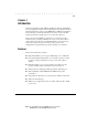
The repeater features several LED indicators that help you monitor the
repeater. The LEDs on the left side of the front panel provide the power ,
activity, and collision status of the repeater. The LEDs above the RJ-45 ports
indicate the link, activity, and partition status for each of the ports. Figure 1-2
shows the LED arrangement for the repeater.
PWR
MDIMDI-X
ACT
COL
UPLINK
12 34 5 6 78
XXXXXXX
Power/Activity/Collision
LED Indicators
RJ45 Port
LED Indicators
Figure 1-3. LED Indicators
The following information lists the possible conditions, colors, and statuses of
each LED and describes the meaning of each condition.
■ PWR LED Steady green indicates that power is supplied to the
repeater. OFF indicates that no power is supplied to the repeater.
■ ACT LED Flashing green indicates that there is activity at one or
more of the repeater's ports.
■ COL LED Flashing yellow indicates that the repeater detects a
collision. OFF indicates that no collisions are occurring.
■ RJ-45 LEDs Steady green indicates that a link condition is present.
Steady yellow indicates that the port is disabled (autopartitioned).
Flashing green indicates that there is activity at the port. Alternately
flashing yellow and green indicates that a link condition is present but
an error condition, such as a jabber, is being detected. OFF indicates
that no link condition is present at the port or there is no connection at
the port.
NOTE: LEDs listed as yellow might appear orange on the repeater's front panel.