
User guide

. . . . . . . . . . . . . . . . . . . . . . . . . . . . . .
2-4 Hardware Description
Writer:
Chris Seiter
Project:
Hardware Description
Comments:
File Name:
1017A_2.DOC
Last Saved On:
8/21/97 9:42 AM
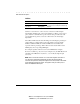
Collision
Label (%) Color Function
1% 3% 5% Green
10% 15+% Amber (yellow)
Indicates the percentage of packet collisions
occurring out of the total packets received by
the hub.
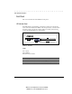
Collisions occur when two or more devices connected to a hub attempt to
transmit data simultaneously on the network. When a collision occurs, devices
pause and then re-transmit after a pseudo-random wait period. Because wait
periods differ among devices, successive collisions become increasingly
improbable.
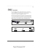
The Collision LEDs assist the network manager in monitoring the percentage of
packet collisions occurring relative to the total packets received by the hub.
Similar to Utilization LEDs, the Collision LEDs have five numbers that
represent collision percentage. When collisions reach a level marked on the
LED display, the corresponding LED lights.
For example, if packet collisions reach 1%, the LED labeled 1% lights.
However, if collisions go beyond 1% (for example, 15%), the LED labeled 15+
and all the other LEDs before it (that is, 1, 3, 5, and 10) also light in rapid
succession.
NOTE: After 32 consecutive collisions occur on the cable segment connected to a
port, that port is automatically partitioned by the hub. The hub automatically
reconnects this port when a data packet longer than 512 bits (normal) is transmitted
by the partitioned port without collision. This applies to all RJ-45 station ports, as
well as the AUI/BNC backbone ports.