
User guide


. . . . . . . . . . . . . . . . . . . . . . . . . . . . . .
1-2 Overview
Writer: Liz Fischer Project: Overview Comments: 268749-001
File Name:749_1.doc Last Saved On:6/19/96 10:46 AM
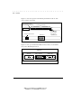
Figure 1-1 shows the repeater's front and back panels and the locations of the
various repeater components:
1
9
2
10
3
11
4
12
5
13
6
14
7
15
8
16
PWR
ACT
COL
MEP
Media Expansion Port
UPLINK
MDI
MDI-X
Power/Activity/Collision
Media Expansion Port LEDs
Power Cord Connector
RJ-45 Ports and LEDs
Back Panel
UPLINK Switch
(for converting
Port 16 to an
uplinkable port)
Figure 1-1. Front and Back Panels of the Repeater
Figure 1-2 shows optional Altermate Media Connectors that you can install in
the repeater's Media Expansion Port:
TXRX
Alternate Media Connectors
(Optional)
BNC Connector
(Thinnet)
AUI Connector
Fiber Connector
(10Base-FL)
Figure 1-2. Alternate Media Connectors