Hardware Reference Guide HP Compaq MultiSeat ms6005 Desktop HP Compaq MultiSeat ms6200 Desktop
© Copyright 2011 Hewlett-Packard Development Company, L.P. The information contained herein is subject to change without notice. Microsoft, Windows, and MultiPoint are either trademarks or registered trademarks of Microsoft Corporation in the United States and/or other countries. The only warranties for HP products and services are set forth in the express warranty statements accompanying such products and services. Nothing herein should be construed as constituting an additional warranty.
About This Book This guide provides basic information for upgrading this computer model. WARNING! Text set off in this manner indicates that failure to follow directions could result in bodily harm or loss of life. CAUTION: Text set off in this manner indicates that failure to follow directions could result in damage to equipment or loss of information. NOTE: Text set off in this manner provides important supplemental information.
iv About This Book
Table of contents 1 Product Features ............................................................................................................... 1 Standard Configuration Features ................................................................................................ 1 Front Panel Components ........................................................................................................... 2 Media Card Reader Components ...................................................................
Removing and Replacing the Primary 3.5-inch Internal SATA Hard Drive ....................... 41 Removing and Replacing a Removable 3.5-inch SATA Hard Drive ................................ 45 3 MultiSeat ms6200 Desktop Hardware Upgrades ............................................................. 50 Serviceability Features ............................................................................................................ 50 Warnings and Cautions ....................................................
Appendix E Computer Operating Guidelines, Routine Care and Shipping Preparation ........ 97 Computer Operating Guidelines and Routine Care .................................................................... 97 Optical Drive Precautions ........................................................................................................ 98 Operation .............................................................................................................. 98 Cleaning ..................................
viii
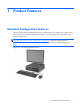
1 Product Features Standard Configuration Features The HP Compaq MultiSeat Desktop features may vary depending on the model. For a complete listing of the hardware and software installed in the computer, run the diagnostic utility (included on some computer models only). NOTE: The MultiSeat Desktop can also be used in a tower orientation.
Front Panel Components Drive configuration may vary by model. Figure 1-2 Front Panel Components Table 1-1 Front Panel Components 1 5.25-inch Optical Drive1 6 USB (Universal Serial Bus) Ports 2 Optical Drive Activity Light 7 Microphone/Headphone Connector 3 Optical Drive Eject Button 8 3.5-inch Media Card Reader (optional)2 4 Dual-State Power Button 9 Hard Drive Activity Light 5 Power On Light 10 Headphone Connector NOTE: The Power On Light is normally green when the power is on.
Media Card Reader Components The media card reader is an optional device available on some models only. Refer to the following illustration and table to identify the media card reader components. Figure 1-3 Media Card Reader Components Table 1-2 Media Card Reader Components No.
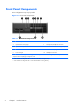
Rear Panel Components Figure 1-4 Rear Panel Components Table 1-3 Rear Panel Components 1 RJ-45 Network Connector 6 DisplayPort Monitor Connector 2 Serial Connector 7 VGA Monitor Connector 3 PS/2 Mouse Connector (green) 8 PS/2 Keyboard Connector (purple) 4 Power Cord Connector 9 Line-Out Connector for powered audio devices (green) 5 Universal Serial Bus (USB) 10 Line-In Audio Connector (blue) NOTE: 4 Arrangement and number of connectors may vary by model.
Keyboard Figure 1-5 Keyboard Components Table 1-4 Keyboard Components 1 1 Function Keys Perform special functions depending on the software application being used. 2 Editing Keys Includes the following: Insert, Home, Page Up, Delete, End, and Page Down. 3 Status Lights Indicate the status of the computer and keyboard settings (Num Lock, Caps Lock, and Scroll Lock). 4 Numeric Keys Work like a calculator keypad. 5 Arrow Keys Used to navigate through a document or Web site.
Using the Windows Logo Key Use the Windows Logo key in combination with other keys to perform certain functions available in the Windows operating system. Refer to Keyboard on page 5 to identify the Windows Logo key. Table 1-5 Windows Logo Key Functions The following Windows Logo Key functions are available in Windows MultiPoint™ Server 2011.
Serial Number Location Each computer has a unique serial number and product ID number in the location shown below. Keep these numbers available for use when contacting customer service for assistance.
2 MultiSeat ms6005 Desktop Hardware Upgrades Serviceability Features The computer includes features that make it easy to upgrade and service. No tools are needed for most of the installation procedures described in this chapter. Warnings and Cautions Before performing upgrades be sure to carefully read all of the applicable instructions, cautions, and warnings in this guide.
CAUTION: Static electricity can damage the electrical components of the computer or optional equipment. Before beginning these procedures, ensure that you are discharged of static electricity by briefly touching a grounded metal object. See Appendix D, Electrostatic Discharge on page 96 for more information. When the computer is plugged into an AC power source, voltage is always applied to the system board.
Removing the Computer Access Panel 1. Remove/disengage any security devices that prohibit opening the computer. 2. Remove all removable media, such as compact discs or USB flash drives, from the computer. 3. Turn off the computer properly through the operating system, then turn off any external devices. 4. Disconnect the power cord from the power outlet and disconnect any external devices.
Replacing the Computer Access Panel Slide the lip on the front end of the access panel under the lip on the front of the chassis (1) then press the back end of the access panel onto the unit so that it locks into place (2).
Removing the Front Bezel 1. Remove/disengage any security devices that prohibit opening the computer. 2. Remove all removable media, such as compact discs or USB flash drives, from the computer. 3. Turn off the computer properly through the operating system, then turn off any external devices. 4. Disconnect the power cord from the power outlet and disconnect any external devices.
Removing Bezel Blanks On some models, there are bezel blanks covering the 3.5-inch and 5.25-inch external drive bays that need to be removed before installing a drive. To remove a bezel blank: 1. Remove the access panel and front bezel. 2. To remove a bezel blank, push the two retaining tabs that hold the bezel blank in place towards the outer right edge of the bezel (1) and slide the bezel blank back and to the right to remove it (2).
Replacing the Front Bezel Insert the three hooks on the bottom side of the bezel into the rectangular holes on the chassis (1) then rotate the top side of the bezel onto the chassis (2) and snap it into place.
Changing from Desktop to Tower Configuration The computer can be used in a tower orientation with an optional tower stand that can be purchased from HP. 1. Remove/disengage any security devices that prohibit opening the computer. 2. Remove all removable media, such as compact discs or USB flash drives, from the computer. 3. Turn off the computer properly through the operating system, then turn off any external devices. 4.
Installing Additional Memory The computer comes with double data rate 3 synchronous dynamic random access memory (DDR3SDRAM) dual inline memory modules (DIMMs). DIMMs The memory sockets on the system board can be populated with up to four industry-standard DIMMs. These memory sockets are populated with at least one preinstalled DIMM. To achieve the maximum memory support, you can populate the system board with up to 16-GB of memory.
Populating DIMM Sockets There are four DIMM sockets on the system board, with two sockets per channel. The sockets are labeled XMM1, XMM2, XMM3, and XMM4. Sockets XMM1 and XMM3 operate in memory channel A. Sockets XMM2 and XMM4 operate in memory channel B.
Installing DIMMs CAUTION: You must disconnect the power cord and wait approximately 30 seconds for the power to drain before adding or removing memory modules. Regardless of the power-on state, voltage is always supplied to the memory modules as long as the computer is plugged into an active AC outlet. Adding or removing memory modules while voltage is present may cause irreparable damage to the memory modules or system board. If you see an LED light on the system board, voltage is still present.
7. Rotate up the external drive bay housing to access the memory module sockets on the system board. Figure 2-8 Rotating the Drive Cage Up 8. Open both latches of the memory module socket (1), and insert the memory module into the socket (2). Figure 2-9 Installing a DIMM NOTE: A memory module can be installed in only one way. Match the notch on the module with the tab on the memory socket. A DIMM must occupy the black XMM4 socket.
10. Repeat steps 8 and 9 to install any additional modules. 11. Replace the access panel. 12. If the computer was on a stand, replace the stand. 13. Reconnect the power cord and turn on the computer. 14. Lock any security devices that were disengaged when the access panel was removed. The computer should automatically recognize the additional memory the next time you turn on the computer.
Removing or Installing an Expansion Card The computer has one PCI expansion slot, two PCI Express x1 expansion slots, and one PCI Express x16 expansion slot. NOTE: The PCI and PCI Express slots support only low profile cards.
5. If the computer is on a stand, remove the computer from the stand. 6. Remove the access panel. 7. Locate the correct vacant expansion socket on the system board and the corresponding expansion slot on the back of the computer chassis. 8. Release the slot cover retention latch that secures the PCI slot covers by lifting the green tab on the latch and rotating the latch to the open position.
9. Before installing an expansion card, remove the expansion slot cover or the existing expansion card. a. If you are installing an expansion card in a vacant socket, remove the appropriate expansion slot cover on the back of the chassis. Pull the slot cover straight up then away from the inside of the chassis.
b. If you are removing a standard PCI card or PCI Express x1 card, hold the card at each end, and carefully rock it back and forth until the connectors pull free from the socket. Pull the expansion card straight up from the socket then away from the inside of the chassis to release it from the chassis frame. Be sure not to scrape the card against the other components. NOTE: Before removing an installed expansion card, disconnect any cables that may be attached to the expansion card.
c. If you are removing a PCI Express x16 card, pull the retention arm on the back of the expansion socket away from the card and carefully rock the card back and forth until the connectors pull free from the socket. Pull the expansion card straight up from the socket then away from the inside of the chassis to release it from the chassis frame. Be sure not to scrape the card against the other components. Figure 2-14 Removing a PCI Express x16 Expansion Card 10.
12. To install a new expansion card, hold the card just above the expansion socket on the system board then move the card toward the rear of the chassis so that the bracket on the card is aligned with the open slot on the rear of the chassis. Press the card straight down into the expansion socket on the system board. Figure 2-15 Installing an Expansion Card NOTE: When installing an expansion card, press firmly on the card so that the whole connector seats properly in the expansion card slot. 13.
16. If the computer was on a stand, replace the stand. 17. Reconnect the power cord and turn on the computer. 18. Lock any security devices that were disengaged when the access panel was removed. 19. Reconfigure the computer, if necessary.
Drive Positions Figure 2-17 Drive Positions Table 2-3 Drive Positions 1 3.5-inch internal hard drive bay 2 3.5-inch external drive bay for optional drives (media card reader shown) 3 5.25-inch external drive bay for optional drives (optical drive shown) NOTE: The drive configuration on your computer may be different than the drive configuration shown above. To verify the type, size, and capacity of the storage devices installed in the computer, run Computer Setup.
Installing and Removing Drives When installing additional drives, follow these guidelines: ● The primary Serial ATA (SATA) hard drive must be connected to the dark blue primary SATA connector on the system board labeled SATA0. ● Connect a SATA optical drive to the white SATA connector on the system board labeled SATA1. ● Connect devices in order of SATA0, SATA1, SATA2, then SATA3 ● Connect an eSATA adapter cable to the orange SATA3 connector.
CAUTION: To prevent loss of work and damage to the computer or drive: If you are inserting or removing a drive, shut down the operating system properly, turn off the computer, and unplug the power cord. Do not remove a drive while the computer is on or in standby mode. Before handling a drive, ensure that you are discharged of static electricity. While handling a drive, avoid touching the connector.
System Board Drive Connections Refer to the following illustration and table to identify the system board drive connectors. Figure 2-19 System Board Drive Connections Table 2-4 System Board Drive Connections No.
Removing an External 5.25-inch Drive CAUTION: All removable media should be taken out of a drive before removing the drive from the computer. To remove a 5.25-inch external drive: 1. Remove/disengage any security devices that prohibit opening the computer. 2. Remove all removable media, such as compact discs or USB flash drives, from the computer. 3. Turn off the computer properly through the operating system, then turn off any external devices. 4.
8. If removing an optical drive, disconnect the power cable (1) and data cable (2) from the rear of the optical drive. Figure 2-21 Disconnecting the Power and Data Cables 9. Rotate the drive cage back down to its normal position. CAUTION: Be careful not to pinch any cables or wires when rotating the drive cage down.
10. Press down on the green drive retainer button located on the left side of the drive to disengage the drive from the drive cage (1). While pressing the drive retainer button, slide the drive back until it stops, then lift it up and out of the drive cage (2). Figure 2-23 Removing the 5.25-inch Drive NOTE: To replace the drive, reverse the removal procedure. When replacing a drive, transfer the four guide screws from the old drive to the new one. Installing an Optical Drive into the 5.
8. Install four M3 metric guide screws in the lower holes on each side of the drive. HP has provided four extra M3 metric guide screws on the front of the chassis, under the front bezel. The M3 metric guide screws are black. Refer to Installing and Removing Drives on page 29 for an illustration of the extra M3 metric guide screws location. CAUTION: Use only 5-mm long screws as guide screws. Longer screws can damage the internal components of the drive.
10. Rotate the drive cage to its upright position. Figure 2-26 Rotating the Drive Cage Up 11. Connect the SATA data cable to the white system board connector labeled SATA1. 12. Route the data cable through the cable guides. CAUTION: There are two cable guides that keep the data cable from being pinched by the drive cage when raising or lowering it. One is located on the bottom side of the drive cage. The other is located on the chassis frame under the drive cage.
14. Rotate the drive cage back down to its normal position. CAUTION: Be careful not to pinch any cables or wires when rotating the drive cage down. Figure 2-28 Rotating the Drive Cage Down 15. Replace the access panel. 16. If the computer was on a stand, replace the stand. 17. Reconnect the power cord and turn on the computer. 18. Lock any security devices that were disengaged when the access panel was removed. The system automatically recognizes the drive and reconfigures the computer.
2. Disconnect the drive cables from the rear of the drive, or, if you are removing a media card reader, disconnect the USB and 1394 cables from the system board as indicated in the following illustrations. NOTE: On some models, the media card reader does not include a 1394 port or cable.
3. Press down on the green drive retainer button located on the left side of the drive to disengage the drive from the drive cage (1). While pressing the drive retainer button, slide the drive back until it stops, then lift it up and out of the drive cage (2). Figure 2-31 Removing a 3.5-inch Drive (Media Card Reader Shown) NOTE: To replace the 3.5-inch drive, reverse the removal procedure. When replacing a 3.5-inch drive, transfer the four guide screws from the old drive to the new one.
3. Position the guide screws on the drive into the J-slots in the drive bay. Then slide the drive toward the front of the computer until it locks into place. Figure 2-32 Installing a Drive into the 3.5-inch Drive Bay (Media Card Reader Shown) 4. Connect the appropriate drive cables: a.
Removing and Replacing the Primary 3.5-inch Internal SATA Hard Drive NOTE: The system does not support Parallel ATA (PATA) hard drives. Before you remove the old hard drive, be sure to back up the data from the old hard drive so that you can transfer the data to the new hard drive. The preinstalled 3.5-inch hard drive is located under the power supply. To remove and replace the hard drive: 1. Remove/disengage any security devices that prohibit opening the computer. 2.
8. Rotate the power supply to its upright position. The hard drive is located beneath the power supply. Figure 2-34 Raising the Power Supply 9. Disconnect the power cable (1) and data cable (2) from the back of the hard drive.
10. Press down on the green release latch next to the hard drive (1). While holding the latch down, slide the drive forward until it stops, then lift the drive up and out of the bay (2). Figure 2-36 Removing the Hard Drive 11. To install a hard drive, you must transfer the silver and blue isolation mounting guide screws from the old hard drive to the new hard drive.
12. Align the guide screws with the slots on the chassis drive cage, press the hard drive down into the bay, then slide it back until it stops and locks in place. Figure 2-38 Installing the Hard Drive 13. Connect the power and data cables to the back of the hard drive. NOTE: When replacing the primary hard drive, be sure to route the SATA and power cables through the cable guide on the bottom of the chassis frame behind the hard drive.
Removing and Replacing a Removable 3.5-inch SATA Hard Drive Some models are equipped with a Removable SATA Hard Drive Enclosure in the 5.25-inch external drive bay. The hard drive is housed in a carrier that can be quickly and easily removed from the drive bay. To remove and replace a drive in the carrier: NOTE: Before you remove the old hard drive, be sure to back up the data from the old hard drive so that you can transfer the data to the new hard drive. 1.
3. Remove the adhesive strip that secures the thermal sensor to the top of the hard drive (1) and move the thermal sensor away from the carrier (2). Figure 2-40 Removing the Thermal Sensor 4. Remove the four screws from the bottom of the hard drive carrier.
5. Slide the hard drive back to disconnect it from the carrier then lift it up and out of the carrier. Figure 2-42 Removing the Hard Drive 6. Place the new hard drive in the carrier then slide the hard drive back so that it seats in the SATA connector on the carrier's circuit board. Be sure the connector on the hard drive is pressed all the way into the connector on the carrier's circuit board.
7. Replace the four screws in the bottom of the carrier to hold the drive securely in place. Figure 2-44 Replacing the Security Screws 8. Place the thermal sensor on top of the hard drive in a position that does not cover the label (1) and attach the thermal sensor to the top of the hard drive with the adhesive strip (2).
9. Slide the cover on the carrier (1) and replace the screw on the rear of the carrier to secure the cover in place (2). Figure 2-46 Replacing the Carrier Cover 10. Slide the hard drive carrier into the enclosure on the computer and lock it with the key provided. NOTE: The carrier must be locked for power to be supplied to the hard drive.
3 MultiSeat ms6200 Desktop Hardware Upgrades Serviceability Features The computer includes features that make it easy to upgrade and service. No tools are needed for most of the installation procedures described in this chapter. Warnings and Cautions Before performing upgrades be sure to carefully read all of the applicable instructions, cautions, and warnings in this guide.
CAUTION: Static electricity can damage the electrical components of the computer or optional equipment. Before beginning these procedures, ensure that you are discharged of static electricity by briefly touching a grounded metal object. See Electrostatic Discharge on page 96 for more information. When the computer is plugged into an AC power source, voltage is always applied to the system board.
Removing the Computer Access Panel To access internal components, you must remove the access panel: 1. Remove/disengage any security devices that prohibit opening the computer. 2. Remove all removable media, such as compact discs or USB flash drives, from the computer. 3. Turn off the computer properly through the operating system, then turn off any external devices. 4. Disconnect the power cord from the power outlet and disconnect any external devices.
Replacing the Computer Access Panel Slide the lip on the front end of the access panel under the lip on the front of the chassis (1) then press the back end of the access panel onto the unit so that it locks into place (2).
Removing the Front Bezel 1. Remove/disengage any security devices that prohibit opening the computer. 2. Remove all removable media, such as compact discs or USB flash drives, from the computer. 3. Turn off the computer properly through the operating system, then turn off any external devices. 4. Disconnect the power cord from the power outlet and disconnect any external devices.
Removing Bezel Blanks On some models, there are bezel blanks covering the 3.5-inch and 5.25-inch drive bays that need to be removed before installing a drive. To remove a bezel blank: 1. Remove the access panel and front bezel. 2. To remove a bezel blank, push the two retaining tabs that hold the bezel blank in place towards the outer right edge of the bezel (1) and slide the bezel blank back and to the right to remove it (2).
Changing from Desktop to Tower Configuration The computer can be used in a tower orientation with an optional tower stand that can be purchased from HP. 1. Remove/disengage any security devices that prohibit opening the computer. 2. Remove all removable media, such as compact discs or USB flash drives, from the computer. 3. Turn off the computer properly through the operating system, then turn off any external devices. 4.
System Board Connections Refer to the following illustration and table to identify the system board connectors for your model. Figure 3-7 System Board Connections Table 3-1 System Board Connections No.
Table 3-1 System Board Connections (continued) No.
In addition, the computer supports: ● 512-Mbit, 1-Gbit, and 2-Gbit non-ECC memory technologies ● single-sided and double-sided DIMMs ● DIMMs constructed with x8 and x16 DDR devices; DIMMs constructed with x4 SDRAM are not supported NOTE: The system will not operate properly if you install unsupported DIMMs. Populating DIMM Sockets There are four DIMM sockets on the system board, with two sockets per channel. The sockets are labeled DIMM1, DIMM2, DIMM3, and DIMM4.
Installing DIMMs CAUTION: You must disconnect the power cord and wait approximately 30 seconds for the power to drain before adding or removing memory modules. Regardless of the power-on state, voltage is always supplied to the memory modules as long as the computer is plugged into an active AC outlet. Adding or removing memory modules while voltage is present may cause irreparable damage to the memory modules or system board. The memory module sockets have gold-plated metal contacts.
7. Rotate up the internal drive bay housing to access the memory module sockets on the system board. Figure 3-8 Rotating the Drive Cage Up 8. Open both latches of the memory module socket (1), and insert the memory module into the socket (2). Figure 3-9 Installing a DIMM NOTE: A memory module can be installed in only one way. Match the notch on the module with the tab on the memory socket. Populate the black DIMM sockets before the white DIMM sockets.
9. Push the module down into the socket, ensuring that the module is fully inserted and properly seated. Make sure the latches are in the closed position (3). 10. Repeat steps 8 and 9 to install any additional modules. 11. Replace the access panel. 12. If the computer was on a stand, replace the stand. 13. Reconnect the power cord and turn on the computer. 14. Lock any security devices that were disengaged when the access panel was removed.
Removing or Installing an Expansion Card The computer has one PCI expansion slot, two PCI Express x1 expansion slots, and one PCI Express x16 expansion slot. NOTE: The PCI and PCI Express slots support only low profile cards. You can install a PCI Express x1, x4, x8, or x16 expansion card in the PCI Express x16 slot. To remove, replace, or add an expansion card: 1. Remove/disengage any security devices that prohibit opening the computer. 2.
9. Before installing an expansion card, remove the expansion slot cover or the existing expansion card. NOTE: Before removing an installed expansion card, disconnect any cables that may be attached to the expansion card. a. If you are installing an expansion card in a vacant socket, remove the appropriate expansion slot cover on the back of the chassis. Pull the slot cover straight up then away from the inside of the chassis. Figure 3-11 Removing an Expansion Slot Cover b.
c. If you are removing a PCI Express x16 card, pull the retention arm on the back of the expansion socket away from the card and carefully rock the card back and forth until the connectors pull free from the socket. Pull the expansion card straight up from the socket then away from the inside of the chassis to release it from the chassis frame. Be sure not to scrape the card against the other components. Figure 3-13 Removing a PCI Express x16 Expansion Card 10.
12. To install a new expansion card, hold the card just above the expansion socket on the system board then move the card toward the rear of the chassis (1) so that the bracket on the card is aligned with the open slot on the rear of the chassis. Press the card straight down into the expansion socket on the system board (2). Figure 3-14 Installing an Expansion Card NOTE: When installing an expansion card, press firmly on the card so that the whole connector seats properly in the expansion card slot. 13.
17. Reconnect the power cord and turn on the computer. 18. Lock any security devices that were disengaged when the access panel was removed. 19. Reconfigure the computer, if necessary. Drive Positions Figure 3-16 Drive Positions Table 3-2 Drive Positions 1 3.5-inch internal hard drive bay 2 3.5-inch drive bay for optional drives (media card reader shown) 3 5.
Installing and Removing Drives When installing drives, follow these guidelines: ● The primary Serial ATA (SATA) hard drive must be connected to the dark blue primary SATA connector on the system board labeled SATA0. If you are adding a second hard drive, connect it to the white connector on the system board labeled SATA1. ● Connect a SATA optical drive to the white SATA connector on the system board labeled SATA2.
2 Silver 6-32 Standard Screws Secondary Hard Drive There are at total of five extra silver 6-32 standard screws. Four are used as guide screws for a secondary hard drive. The fifth is used for bezel security (see Front Bezel Security on page 94 for more information). CAUTION: To prevent loss of work and damage to the computer or drive: If you are inserting or removing a drive, shut down the operating system properly, turn off the computer, and unplug the power cord.
Removing a 5.25-inch Drive from a Drive Bay CAUTION: All removable media should be taken out of a drive before removing the drive from the computer. 1. Remove/disengage any security devices that prohibit opening the computer. 2. Remove all removable media, such as compact discs or USB flash drives, from the computer. 3. Turn off the computer properly through the operating system, then turn off any external devices. 4.
8. If removing an optical drive, disconnect the power cable (1) and data cable (2) from the rear of the optical drive. CAUTION: When removing the cables, pull the tab or connector instead of the cable itself to avoid damaging the cable. Figure 3-19 Disconnecting the Power and Data Cables 9. Rotate the drive cage back down to its normal position. CAUTION: Be careful not to pinch any cables or wires when rotating the drive cage down.
10. Press down on the green drive retainer button located on the left side of the drive to disengage the drive from the drive cage (1). While pressing the drive retainer button, slide the drive back until it stops, then lift it up and out of the drive cage (2). Figure 3-21 Removing the 5.25-inch Drive Installing a 5.25-inch Drive into a Drive Bay 1. Remove/disengage any security devices that prohibit opening the computer. 2.
8. Install four M3 metric guide screws in the lower holes on each side of the drive. HP has provided four extra M3 metric guide screws on the front of the chassis, under the front bezel. The M3 metric guide screws are black. Refer to Installing and Removing Drives on page 68 for an illustration of the extra M3 metric guide screws location. NOTE: When replacing the drive, transfer the four M3 metric guide screws from the old drive to the new one. CAUTION: Use only 5-mm long screws as guide screws.
10. Rotate the drive cage to its upright position. Figure 3-24 Rotating the Drive Cage Up 11. Connect the SATA data cable to the white SATA system board connector labeled SATA2. 12. Route the data cable through the cable guides. CAUTION: There are two cable guides that keep the data cable from being pinched by the drive cage when raising or lowering it. One is located on the bottom side of the drive cage. The other is located on the chassis frame under the drive cage.
14. Rotate the drive cage back down to its normal position. CAUTION: Be careful not to pinch any cables or wires when rotating the drive cage down. Figure 3-26 Rotating the Drive Cage Down 15. Replace the front bezel (if removed) and access panel. 16. If the computer was on a stand, replace the stand. 17. Reconnect the power cord and turn on the computer. 18. Lock any security devices that were disengaged when the access panel was removed. Removing a 3.
2. Disconnect the drive cables from the rear of the drive, or, if you are removing a media card reader, disconnect the USB cable from the system board as indicated in the following illustration. Figure 3-27 Disconnecting the Media Card Reader USB Cable 3. Press down on the green drive retainer button located on the left side of the drive to disengage the drive from the drive cage (1).
Installing a 3.5-inch Drive into a Drive Bay The 3.5-inch bay is located underneath the 5.25-inch drive. To install a drive into the 3.5-inch bay: NOTE: Install guide screws to ensure the drive will line up correctly in the drive cage and lock in place. HP has provided extra guide screws for the drive bays (four 6-32 standard screws and four M3 metric screws), installed in the front of the chassis, under the front bezel. A secondary hard drive uses 6-32 standard screws.
5. Connect the appropriate drive cables: a. If installing a second hard drive, connect the power cable (1) and data cable (2) to the rear of the drive and connect the other end of the data cable to the white connector on the system board labeled SATA1. Figure 3-31 Connecting the Secondary Hard Drive Power Cable and Data Cable b. If installing a media card reader, connect the USB cable from the media card reader to the USB connector on the system board labeled MEDIA.
9. Reconnect the power cord and turn on the computer. 10. Lock any security devices that were disengaged when the access panel was removed. Removing and Replacing the Primary 3.5-inch Internal Hard Drive NOTE: Before you remove the old hard drive, be sure to back up the data from the old hard drive so that you can transfer the data to the new hard drive. The preinstalled 3.5-inch hard drive is located under the power supply. To remove and replace the hard drive: 1.
8. Rotate the power supply to its upright position. The hard drive is located beneath the power supply. Figure 3-34 Raising the Power Supply 9. Disconnect the power cable (1) and data cable (2) from the back of the hard drive.
10. Press down on the green release latch next to the hard drive (1). While holding the latch down, slide the drive forward until it stops, then lift the drive up and out of the bay (2). Figure 3-36 Removing the Hard Drive 11. To install a hard drive, you must transfer the silver and blue isolation mounting guide screws from the old hard drive to the new hard drive.
12. Align the guide screws with the slots on the chassis drive cage, press the hard drive down into the bay, then slide it back until it stops and locks in place. Figure 3-38 Installing the Hard Drive 13. Connect the power cable (1) and data cable (2) to the back of the hard drive. NOTE: If the system has only one SATA hard drive, the data cable must be connected to the dark blue connector labeled SATA0 on the system board to avoid any hard drive performance problems.
A Specifications Table A-1 Specifications Desktop Dimensions (in the desktop position) Height 3.95 in 10.0 cm Width 13.3 in 33.8 cm Depth 14.9 in 37.8 cm Approximate Weight 19 lb 8.6 kg Weight Supported (maximum distributed load in desktop position) 77 lb 35 kg Operating 50° to 95°F 10° to 35°C Nonoperating -22° to 140°F -30° to 60°C Temperature Range NOTE: Operating temperature is derated 1.0° C per 300 m (1000 ft) to 3000 m (10,000 ft) above sea level; no direct sustained sunlight.
Table A-1 Specifications (continued) Power Supply 115V 230V Operating Voltage Range (STD PS) 90-264 VAC 90-264 VAC Operating Voltage Range (EPA 87/89/85% @ 20/50/100% load PS) 90-264 VAC 90-264 VAC Rated Voltage Range (STD PS) 100-240 VAC 100-240 VAC Rated Voltage Range (EPA 87/89/85% @ 20/50/100% load PS) 100-240 VAC 100-240 VAC Rated Line Frequency 50-60 Hz 50-60 Hz Power Output 240W 240W STD PS 4A @ 100 VAC 2A @ 230 VAC EPA 87/89/85% @ 20/50/100% load PS 4A @ 100 VAC 2A @ 230 VA
B Battery Replacement The battery that comes with the computer provides power to the real-time clock. When replacing the battery, use a battery equivalent to the battery originally installed in the computer. The computer comes with a 3-volt lithium coin cell battery. WARNING! The computer contains an internal lithium manganese dioxide battery. There is a risk of fire and burns if the battery is not handled properly. To reduce the risk of personal injury: Do not attempt to recharge the battery.
7. Locate the battery and battery holder on the system board. NOTE: On some computer models, it may be necessary to remove an internal component to gain access to the battery. 8. Depending on the type of battery holder on the system board, complete the following instructions to replace the battery. Type 1 a. Lift the battery out of its holder. Figure B-1 Removing a Coin Cell Battery (Type 1) b. Slide the replacement battery into position, positive side up.
Type 3 a. Pull back on the clip (1) that is holding the battery in place, and remove the battery (2). b. Insert the new battery and position the clip back into place. Figure B-3 Removing a Coin Cell Battery (Type 3) NOTE: After the battery has been replaced, use the following steps to complete this procedure. 9. Replace the access panel. 10. If the computer was on a stand, replace the stand. 11. Plug in the computer and turn on power to the computer. 12.
C Installing a Security Lock The security locks displayed below and on the following pages can be used to secure the computer.
Padlock Figure C-2 Installing a Padlock Padlock 89
HP Business PC Security Lock 1. Fasten the security cable by looping it around a stationary object. Figure C-3 Securing the Cable to a Fixed Object 2. Insert the Kensington lock into the Kensington lock slot on the back of the monitor and secure the lock to the monitor by inserting the key into the key hole on the rear of the lock and rotating the key 90 degrees.
3. Slide the security cable through the hole in the Kensington lock on the rear of the monitor. Figure C-5 Securing the Monitor 4. Use the bracket provided in the kit to secure other peripheral devices by laying the device cable across the center of the bracket (1) and inserting the security cable through one of the two holes in the bracket (2). Use the hole in the bracket that best secures the peripheral device cable.
5. Thread the keyboard and mouse cables through the computer chassis lock. Figure C-7 Threading the Keyboard and Mouse Cables 6. Screw the lock to the chassis in the thumbscrew hole using the screw provided.
7. Insert the plug end of the security cable into the lock (1) and push the button in (2) to engage the lock. Use the key provided to disengage the lock. Figure C-9 Engaging the Lock 8. When complete, all devices in your workstation will be secured.
Front Bezel Security The front bezel can be locked in place by installing a security screw provided by HP. To install the security screw: 1. Remove/disengage any security devices that prohibit opening the computer. 2. Remove all removable media, such as compact discs or USB flash drives, from the computer. 3. Turn off the computer properly through the operating system, then turn off any external devices. 4. Disconnect the power cord from the power outlet and disconnect any external devices.
9. Install the security screw next to the middle front bezel release tab to secure the front bezel in place. Figure C-12 Installing the Front Bezel Security Screw 10. Replace the access panel. 11. If the computer was on a stand, replace the stand. 12. Reconnect the power cord and turn on the computer. 13. Lock any security devices that were disengaged when the access panel was removed.
D Electrostatic Discharge A discharge of static electricity from a finger or other conductor may damage system boards or other static-sensitive devices. This type of damage may reduce the life expectancy of the device. Preventing Electrostatic Damage To prevent electrostatic damage, observe the following precautions: ● Avoid hand contact by transporting and storing products in static-safe containers.
E Computer Operating Guidelines, Routine Care and Shipping Preparation Computer Operating Guidelines and Routine Care Follow these guidelines to properly set up and care for the computer and monitor: ● Keep the computer away from excessive moisture, direct sunlight, and extremes of heat and cold. ● Operate the computer on a sturdy, level surface. Leave a 10.2-cm (4-inch) clearance on all vented sides of the computer and above the monitor to permit the required airflow.
Optical Drive Precautions Be sure to observe the following guidelines while operating or cleaning the optical drive. Operation ● Do not move the drive during operation. This may cause it to malfunction during reading. ● Avoid exposing the drive to sudden changes in temperature, as condensation may form inside the unit. If the temperature suddenly changes while the drive is on, wait at least one hour before you turn off the power. If you operate the unit immediately, it may malfunction while reading.
Index Symbols/Numerics , ms6200 65 A audio connectors 2, 4 B battery replacement 85 C cable lock 88 computer access panel, ms6005 removing 10 replacing 11 computer access panel, ms6200 removing 52 replacing 53 computer operating guidelines 97 connecting drive cables, ms6005 29 connecting drive cables, ms6200 68 D DIMMs.
L line-in connector 4 line-out connector 4 locks 88 cable lock 88 front bezel 94 HP Business PC Security Lock 90 padlock 89 M media card reader features 3 media card reader, ms6005 installing 39 removing 37 media card reader, ms6200 installing 77 removing 75 memory, ms6005 installing 16 populating sockets 17 specifications 16 memory, ms6200 installing 58 populating sockets 59 specifications 58 microphone connector 2 monitor connector DisplayPort 4 VGA 4 mouse connector 4 ms6005 3.
front bezel 12, 54 hard drive 41 media card reader 37 optical drive 32 PCI card 24 PCI Express card 25 removing, ms6200 bezel blanks 55 computer access panel 52 expansion card 63 expansion slot cover 64 hard drive 79 media card reader 75 optical drive 70 PCI card 64 W Windows Logo key 6 S safety 98 security 88 cable lock 88 front bezel 94 HP Business PC Security Lock 90 padlock 89 serial connector 4 serial number location 7 shipping preparation 98 specifications computer 83 specifications, ms6005 memory 1