DIGITAL 2T-CCMHA-CB Central Office Memory Channel Hub Installation/Service Guide Part Number: EK-MCHCO-IN.
December 1998 The information in this publication is subject to change without notice. COMPAQ COMPUTER CORPORATION SHALL NOT BE LIABLE FOR TECHNICAL OR EDITORIAL ERRORS OR OMISSIONS CONTAINED HEREIN, NOR FOR INCIDENTAL OR CONSEQUENTIAL DAMAGES RESULTING FROM THE FURNISHING, PERFORMANCE, OR USE OF THIS MATERIAL.
Table of Contents 1 Introduction 1.1 Overview .......................................................................................................... 1–1 1.2 Components and Controls ................................................................................. 1–1 1.2.1 Front Components ................................................................................... 1–1 1.2.2 Operator Control Panel............................................................................ 1–3 1.2.
3 Removal and Replacement 3.1 Introduction ...................................................................................................... 3–1 3.2 Top Cover......................................................................................................... 3–3 3.3 Power Supply.................................................................................................... 3–4 Figures Figure 1-1 Front Components .................................................................................
Preface Overview This guide provides the information necessary to install the 2T-CCMHA-CB central office Memory Channel hub in a 48.26-cm (19-in.) NEBS 2000/ETSI-compliant cabinet with an EIA rail-hole pattern. It also provides information on removing and replacing the top cover and the power supply.
Chapter 3,.Removal and Replacement – Provides the removal and replacement procedures for the top cover and power supply.
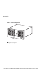
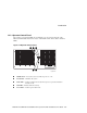
1 Introduction 1.1 Overview The 2T-CCMHA-CB central office Memory Channel hub is used to share and route data between two AlphaServer 4100 central office systems. 1.2 Components and Controls System components and controls are located at the front, internally, and at the rear of the Memory Channel hub chassis. 1.2.1 Front Components Figure 1-1 shows the components located on the front of the Memory Channel hub chassis.
Introduction Figure 1-1 Front Components 1 DIGITAL Memory Cha Central nnel Hub 100/8 Office LJ-06497.
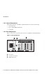
Introduction 1.2.2 Operator Control Panel The operator control panel (OCP), shown in Figure 1-2, is located on the front of the Memory Channel hub chassis and consists of an On/Off switch, a Reset button, and three LEDs. Figure 1-2 Operator Control Panel 3 4 5 DIGITAL Memory Channel Hub 100/8 Central Office 2 1 LJ-06498.AI7 On/Off switch — Powers the system secondary dc power on or off. Reset button — Initializes the system. Turbo LED — Lit when computer runs at rated microprocessor speed.
Introduction 1.2.3 Internal Components The internal components of the Memory Channel hub chassis consist of the following: • One motherboard • Four to eight CCMLA hub linecards • Cooling fan 1.2.4 Rear Components Figure 1-3 shows the components located on the rear of the Memory Channel hub chassis. Figure 1-3 Rear Components 3 1 2 7 6 5 4 3 2 1 0 LJ-06499.
Introduction 1.3 Specifications Table 1-1 contains the physical, environmental, and electrical specifications for the 2TCCMHA-CB central office Memory Channel hub. Table 1-1 2T-CCMHA-CB Central Office Memory Channel Hub Specifications Physical Characteristics Chassis Weight 13.6 kg (30 lb.) Length 40.64 cm (16 in.) Width 48.26 cm (19.0 in.) Height 17.78 cm (7.00 in.
SES Template Word 7 Blank Page Fix by Peter LaQuerre
2 Installation 2.1 General This chapter covers the installation of the 2T-CCMHA-CB central office Memory Channel hub in a 48.26-cm (19-in.) NEBS 2000/ETSI-compliant cabinet with an EIA rail-hole pattern.
Installation • The system is located in an area that provides sufficient clearance for ventilation and servicing. A clearance of 61 cm (24 in.) at the rear and 129.6 cm (51 in.) at the front of the cabinet is required for service. ________________________ Caution ___________________________ Do not impede airflow by obstructing the front and rear of the cabinet. Exceeding internal thermal limits can affect system reliability.
Installation ________________________WARNING __________________________ The 2T-CCMHA-CB central office Memory Channel hub can weigh up to 13.6 kg (30 lb.). Use sufficient personnel or the proper lifting equipment when lifting or moving the system. ____________________________________________________________ ________________________ACHTUNG __________________________ Der 2T-CCMHA-CB Central Office Memory Channel Hub kann bis zu 13,6 kg (30 lb) wiegen.
Installation 2.4 Installing the 2T-CCMHA-CB Central Office Memory Channel Hub The following sections contain the procedure for installing the 2T-CCMHA-CB central office Memory Channel hub in a 48.26-cm (19-in.) NEBS 2000/ETSI-compliant cabinet with an EIA rail-hole pattern. Tools Required • Phillips-head screwdriver • Flat-blade screwdriver • Adjustable wrench 2.4.1 Determining the Installation Area The 2T-CCMHA-CB central office Memory Channel hub requires 22.23 cm (8.75 in.
Installation Figure 2-1 Installation Area and Rail-Hole Pattern (EIA Rail-Hole Pattern) 4 4 8 3/4" 7" "Installation Area" 5 1/4" 3 2 1 0.625 inch 0.625 inch 0.500 inch 0.625 inch 0.625 inch 0.500 inch 0.625 inch 0.625 inch 0.500 inch 0.625 inch 3 1/2" 3 2 1 3/4" 1 "1.75 Rule" LJ-06500.AI4 Hole 1 for attaching left and right slide brackets. Hole 2 for installing standoffs on left and right front rails. Hole 3 for attaching left and right slide brackets.
Installation 2.4.2 Attaching the Slide Assemblies to the Cabinet Rails The following sections contain the procedures for attaching the right and left slide assembles to the cabinet rails. 2.4.2.1 Attaching the Right Slide Assembly to the Cabinet Rails To attach the right slide assembly to the cabinet rails, refer to Figure 2-2 and proceed as follows: 1. Determine the proper mounting holes for the right slide brackets.
Installation Figure 2-2 Attaching the Slide Assemblies to the Cabinet Rails 3 4 3 4 1 1 2 2 LJ-06501.AI7 2.4.2.2 Attaching the Left Slide Assembly to the Cabinet Rails To attach the left slide assembly to the cabinet rails, refer to Figure 2-2 and proceed as follows: 1. Determine the proper mounting holes for the left slide brackets. The proper mounting holes are the 1st, 2nd, and 3rd holes of the installation area (see Figure 2-1). 2. Locate the left slide assembly. 3.
Installation 5. 6. 7. Install a 10-32 standoff in the 2nd hole of the installation area on the left front rail. Tighten this standoff. Place the left rear slide bracket on the inside of the left rear rail and align the three slide bracket holes and with the 1st, 2nd, and 3rd holes of the installation area on the left rear rail. Install three 10-32 truss-head screws in the 1st, 2nd, and 3rd, holes of the installation area to secure the left rear slide bracket to the left rear rail, but do not tighten.
Installation 2.4.3 Attaching the Inner Races to the Tray To attach the inner slide races to the tray, refer to Figure 2-3 and proceed as follows: _________________________ Caution ___________________________ When performing this procedure, ensure that the locking lever is on the outside of the inner slide race. Otherwise, the slide will be damaged when the system is installed on the slide assemblies.
Installation 2.4.4 Mounting the Memory Channel Hub, Front Bezel, and Interlock Actuator Bracket on the Tray To mount the 2T-CCMHA-CB central office Memory Channel hub, front bezel, and interlock actuator bracket on the tray, refer to Figure 2-4 and proceed as follows: _______________________ WARNING__________________________ The 2T-CCMHA-CB central office Memory Channel hub can weigh up to 13.6 kg (30 lb.). Use sufficient personnel or the proper lifting equipment when lifting or moving the system.
Installation Figure 2-4 Mounting the Memory Channel Hub, Front Bezel, and Interlock Actuator Bracket on the Tray 3 5 3 3 4 5 1 2 6 7 LJ-06502A.
Installation 2.4.5 Mounting the Chassis and Tray Assembly on the Slides To mount the chassis and tray assembly on the slides, refer to Figure 2-5 and proceed as follows: _______________________ WARNING__________________________ The 2T-CCMHA-CB central office Memory Channel hub can weigh up to 13.6 kg (30 lb.). Use sufficient personnel or the proper lifting equipment when lifting or moving the system.
Installation Figure 2-5 Mounting the Chassis and Tray Assembly on the Slides 1 3 1 DIGITAL Memory Central Channel Hub 100/8 Office 3 2 4 LJ-06504.
Installation 2.5 Installing the Interlock System The interlock system helps prevent cabinet instability by allowing only one system at a time to be pulled out of the cabinet. The interlock system consists of a vertical rod on which are mounted actuator latches for each product installed in the cabinet. These actuator latches engage the interlock actuator bracket on the rear of rackmount systems.
Installation __________________________ Note _____________________________ The interlock system is compatible with the 2T-CCMHA-CB central office Memory Channel hub. Other systems may not be compatible because the interlock actuator bracket may not engage properly. In these cases, do not install the interlock actuator bracket on those systems.
Installation Figure 2-6 The Interlock System B A 5 2 1 B 1 A 2 1 4 5 LJ-06471.
3 Removal and Replacement 3.1 Introduction This chapter contains the procedures for removing and replacing the top cover and power supply of the 2T-CCMHA-CB central office Memory Channel hub: For troubleshooting information and the procedure for removing the CCMLA linecards, motherboard, hub fan assembly, and hub control panel, refer to the Memory Channel Service Information manual.
Removal and Replacement _______________________ WARNING__________________________ Only a qualified service person should remove and replace components in the 2T-CCMHA-CB central office Memory Channel hub. A qualified service person should have the technical training and experience necessary to be aware of the hazards to which they are exposed in performing a task and the measures that should be taken to minimize the danger to themselves or other persons.
Removal and Replacement 3.2 Top Cover _________________________ Caution ___________________________ Use care when removing and replacing the cover to prevent damage to the RFI gaskets that are located around the cover and opening. ____________________________________________________________ Perform the following procedure to remove the top cover: 1. Unlock the top cover by turning the key, located on the rear of the chassis, clockwise to the unlock position (see Figure 3-1).
Removal and Replacement 3.3 Power Supply Perform the following procedure to remove the power supply: 1. Remove the top cover (see Section 3.2). 2. Remove the four screws on the rear of the chassis that secure the power supply (see Figure 3-2). 3. 4. Loosen the two screws and disconnect the power cable connector from the power supply (see Figure 3-3). Slide the power supply toward the front of the chassis until it is free and then lift the power supply out of the chassis.
Removal and Replacement Figure 3-3 Disconnecting the Power Cable Connector and Removing the Power Supply 2 1 7 6 5 4 3 2 1 0 LJ-06514.
SES Template Word 7 Blank Page Fix by Peter LaQuerre