Thank you for purchasing this Factory Service Manual CD/DVD from servicemanuals4u.com.
Notice The information in this guide is subject to change without notice. Compaq Computer Corporation shall not be liable for technical or editorial errors or omissions contained herein; nor for incidental or consequential damages resulting from the furnishing, performance, or use of this material. This guide contains information protected by copyright. No part of this guide may be photocopied or reproduced in any form without prior written consent from Compaq Computer Corporation.
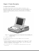
Chapter 1. Product Description 1.1 Computer Features and Models The Compaq LTE 5000 Family of Personal Computers introduces a new generation of performance notebook computers with advanced modularity, Pentium processors with 64-bit architecture, PCI local bus graphics, and extensive multimedia support. This full- function family of notebook computers allows desktop functionality and connectivity via an optional expansion base. 1.1.
o 8 or 16 MB of RAM, expandable to 72 or 80 MB o 512 KB of 64-bit write-back, synchronous, level-2 cache memory available on the LTE5400 model; 256 KB of 64-bit write-back, synchronous, level-2 cache memory available on all other models o Upgradable flash ROM BIOS o High-performance 32-bit PCI local bus graphics with hardware-assisted Motion Video Acceleration (MVA) o Color TFT VGA or SVGA, CSTN VGA or SVGA, or CTFT 1024 x 768 display panels o Keyboard with built-in EasyPoint II pointing device and mouse bu
810 CD CTFT CTFT/SVGA --------------------------------------------------------------------------LTE 5150 Model Pentium/100 11.3-inch 810 MB Yes 810 CSTN 800 CTFT/SVGA x 600 --------------------------------------------------------------------------LTE 5200 Model Pentium/120 10.4-inch 1.35 GB Optional 1350 CTFT CTFT/SVGA --------------------------------------------------------------------------LTE 5250 Model Pentium/120 10.
o Compaq PCMCIA 3.14 o Logitech Mouse Ware 6.46 o PUMA TranXit Version 1.03 o Microsoft Video for Windows 1.10e (Runtime version) o Machine Check Version 1.1 (MACHCHK.SYS) o SystemSoft Suspend-To-Disk Utility 2.20.00 (0VMAKFIL.EXE) o Compaq Supplementary Programs o Microsoft Supplementary Programs o SAFETY & COMFORT GUIDE o COMPAQ DICTIONARY o COMPAQ USER'S GUIDE o ONLINE OPTIONS CATALOG o Compaq Diagnostics for Windows 1.05 o CompuServe WinCIM (1.4/1.2/1.31D/1.
LAN management tools from Compaq and other leading vendors to make Compaq portable computers easier to inventory, troubleshoot, and protect. Asset Management AssetControl is asset management software designed to cut the time and cost of conducting a physical inventory of personal computers, key components, and monitors.
1.1.5 Security Features The computer has the following security features: o Ability to secure drives in the dedicated hard drive bay and computer MultiBay o Ability to secure the computer and either MultiBay Expansion Base to an immovable object with an optional cable lock o Ability to establish power-on and setup passwords and to disable ports and devices from the Security menu in Computer Setup 1.1.
- Two CD-ROM drives: You can have one in the expansion base and one in the computer; either drive can be data or audio. If both drives are in the expansion base, they must be for data only. - One CD-ROM drive: It can be either data or audio and in either the computer or expansion base.
o 3.5-inch 1.44 MB Diskette Drive o 510 MB IDE Hard Drive o 810 MB IDE Hard Drive o 1.35 GB IDE Hard Drive o 2.16 GB w/DFP IDE Hard Drive o 2.16 GB IDE Hard Drive Diskette Drive The computer uses a 3.5-inch diskette drive that is enclosed in a module that fits into the MultiBays of the computer or the MultiBay Expansion Base and the MultiBay ISA Expansion Base. The diskette drive is a three-mode type that is compatible with 1.44 MB, 1.2 MB and 720K AT drive types.
1.2.5 MPEG and TV Video Adapter The MPEG and TV Video Adapter option is supported with the computer and both expansion bases. This option provides an MPEG decoder for high quality digital video playback with Windows scaling and interleaved stereo audio, S-Video I/O for laser disc quality playback video, and composite video supporting the NTSC/PAL formats. 1.2.
o Fast charging of two batteries in 3 hours It requires the AC Adapter or Automobile Adapter for power. Chapter 1.3 Computer External Components The external components on the front and right sides of the computer are shown in Figure 1-2 and are described in Table 1-3. Table 1-3.
=========================================================================== Item Component Function =========================================================================== 1 Power switch Turns the power on and off. --------------------------------------------------------------------------2 Display switch Turns display off and initiates beep if display is closed with computer on. When used with the standby button, restarts the computer.
--------------------------------------------------------------------------5 Ventilation intake Intake vents provide proper airflow to help prevent the computer from overheating. --------------------------------------------------------------------------6 Stereo speakers Built-in stereo speakers for PC and multimedia sound system. --------------------------------------------------------------------------7 Latch Secures computer in a closed position; release to open.
Table 1-4. Computer Components - Rear and Left Sides =========================================================================== Item Component Function =========================================================================== 1 Serial number Identifies the computer. --------------------------------------------------------------------------2 Serial connector Connects optional serial devices.
--------------------------------------------------------------------------10 Docking sensor Access to a microswitch that initiates the docking scenario when the computer is being docked. Also serves as a guide for the MPEG Adapter. --------------------------------------------------------------------------11 Mono microphone jack Connects a powered electric condenser microphone.
o Super I/O (National 87334) o Audio controller (ESS688 or ESS1688) o Power controller (47P440AF) The boards on which these controllers reside are identified in the sections that follow. 1.4.
The following LCD panels are supported: o 10.4-inch (26.4 cm) CSTN VGA Display (640 x 480) o 11.3-inch (28.7 cm) CSTN SVGA Display (800 x 600) o 10.4-inch (26.4 cm) CTFT VGA Display (640 x 480) o 10.4-inch (26.4 cm) CTFT VGA Display (800 x 600) o 11.3-inch (28.7 cm) CTFT SVGA Display (800 x 600) o 12.1-inch (30.7 cm) CTFT SVGA (800 x 600) o 12.1-inch (30.7 cm) CTFT 1024 x 768 Display Both LCD panels have a controllable backlight intensity that can be adjusted with a slide switch.
Release Latches The release latches serve to lock the display and system units together when the computer is in the closed position. Each latch assembly consists of three parts: o Latch actuator o Latch hook o Latch spring The release latch assembly is available as a field replaceable unit. The display bezel must be removed to replace the latch assemblies. The release latches are mounted in the display unit back cover. The display bezel must be removed to access the latches.
The system unit contains the following field replaceable units: o CPU cover o Internal microphone o Status panel o Processor board o Power board o Cooling fan o System board o Memory expansion board (optional) o Keyboard assembly o Auxiliary battery o Miscellaneous plastic parts CPU Cover The CPU cover is located above the keyboard and is secured in place with three screws on the rear panel of the system unit. Tabs on the front edge of the CPU cover engage slots across the top edge of the keyboard panel.
to the system board. It is an omnidirectional condenser microphone with a standard sensitivity of 40dB. The microphone is mounted in a rubber boot to provide acoustic isolation and is mounted at the right side of the keyboard, under the CPU cover. Status Panel The status panel is located immediately below the LCD panel on the system unit. The panel displays a series of icons to indicate system status as described in Table 1-3. The status panel also contains two status indicator lights.
The L2 cache is implemented as direct-mapped, write-back cache with a size of 256 KB. The power switch, display switch, and standby (suspend) button are mounted on the processor board. They are operated by switch actuators mounted on the CPU cover. The power switch turns system power on and off. When the switch is pushed to turn the power off, the system displays a warning message that all unsaved data will be lost. The shut down process is then completed by pressing Enter.
LTE 5250 10.4 in SVGA CTFT 2-3 2-3 2-3 LTE 5380 12.1 in 1024 x 768 CTFT 2-3 1-2 1-2 LTE 5400 12.1 in 1024 x 768 CTFT 2-3 2-3 2-3 =========================================================================== The power-on password jumper is also located on the processor board. To erase the power-on password, set jumper JP1 to pins 1 and 2; set JP1 to pins 2 and 3 for normal operation. See Chapter 2 for more details.
o PCI BIOS o Keyboard Controller Firmware for the Intel 80C51SL o VGA BIOS The ROM-based setup has been translated into ten languages in addition to English. Messages that are displayed by the BIOS which require no user interaction are displayed in English. This includes POST warning messages, error messages, and runtime warnings and notifications. Messages that are displayed by the BIOS which require user interaction are translated into the same language as Setup.
drive can be used simultaneously. The audio subsystem is integrated into the system board. The system supports an internal microphone, stereo speakers, SoundBlaster PRO compatible audio, CD-ROM audio inputs, an external jack for headphones or speakers, microphone jack, and line-input jack. Line and CD-ROM inputs and the speaker outputs are passed through the external options connector and supported by both expansion bases.
support up to four IDE hard drives. When using two hard drives in the computer, one of the hard drives is installed in the dedicated hard drive bay and the other in the MultiBay. NOTE: The dedicated hard drive bay provides limited support for the Compaq LTE Elite hard drive. See Appendix C for details. The hard drive remains powered off from Standby (Suspend) until the first access occurs. The hard drive is powered off during Standby (Suspend).
A connector on the rear of the computer interfaces with either expansion base to provide additional functionality. The expansion base replicates the following computer connectors: o Serial connector o Parallel connector o External monitor connector o PS/2-compatible mouse connector o Power connector o External keyboard connector o All audio connectors except mono microphone jack Additional MultiBay Expansion Base and MultiBay ISA details are presented in Section 1.5.
The battery release mechanism consists of the following parts: o Battery release actuator o Battery release spring o Battery release holder o Battery release hook o Battery release hook spring All of these components are included in the Latches Kit. The battery release spring maintains the mechanism in the latched state until the release actuator is pushed. This action retracts the release hook from the battery. The release hook spring ensures that the battery hook firmly engages the battery.
to the keyboard. Once released, the flat cable can be disconnected from the ZIF connector on the underside of the controller. MultiBay The MultiBay accommodates the following devices: o Dual-speed, quad-speed, or 6x CD-ROM drive o Second hard drive o Second battery pack o 3.5-inch diskette drive NOTE: The hard drive must be mounted in the MultiBay hard drive carrier before it can be installed into the MultiBay.
o Security features o Stereo speakers o ISA expansion slot (MultiBay ISA Expansion Base) o High performance stereo speakers and new audio bass ports on both sides of the expansion base for Compaq PremierSound audio system (MultiBay ISA Expansion Base) Chapter 1.6 MultiBay Expansion Base and MultiBay ISA Expansion Base Components The external components on the front and right sides of the expansion base are shown in Figure 1-4 and described in Table 1-7. Table 1-7.
4 MultiBay II device release button 5 MultiBay II 6 PC Card release buttons 7 Ventilation exhausts (MultiBay ISA Expansion Base model) 8 PC Card slots 9 ISA slot access door (MultiBay ISA Expansion Base model) 10 Stereo speaker (MultiBay ISA Expansion Base model) 11 Security cable slot 12 Docking lever 13 Audio bass port (MultiBay ISA Expansion Base model) 14 Battery lights 15 Docking aid =========================================================================== Additional components
Table 1-8.
13 AC power connector =========================================================================== The external components on the rear panel of the expansion base are shown in Figure 1-6 and described in Table 1-9. Table 1-9.
9 Parallel connector 10 Serial connector 11 Auxiliary fan (MultiBay ISA Expansion Base model) 12 MPEG and TV Video Adapter connector 13 ISA slot cover (MultiBay ISA Expansion Base model) =========================================================================== Chapter 1.
The MultiBay connector board is mounted between the two MultiBays and serves to route the appropriate signals to the MultiBay connectors. 1.7.3 Power Supply The power supply is an AC-to-DC converter that serves the same function as the AC adapter and DC-to-DC converter in the computer. It provides regulated DC power for all of the subsystems. The expansion base uses a standard AC power cord that connects directly to the power supply. An external fan mounted on the power supply provides cooling.
Table 1-10.
Table 1-11.
to charge batteries. MultiBay I will accept Compaq LTE Elite hard drives. 1.7.7 PC Card Slots Each expansion base has two Type III PC Card slots to the PC card slots on the computer. Each PC Card base supports one Type I, one Type II, or one Type serviceable part of the PC card slots are the slot connectors are incorporated into the main board. that function similarly slot on the expansion III PC Card. The only doors. The rails and 1.7.
The Compaq MPEG and TV Video Adapter option provides enhanced MPEG capabilities for use with the Compaq LTE 5000 Family of Personal Computers. To achieve maximum MPEG functionality support, use the Compaq MPEG and TV Video Adapter option. o Due to the vast numbers of ISA expansion boards that are available, Compaq does not guarantee or support every ISA expansion board. Refer to the documentation accompanying the ISA expansion board being installed for complete installation and configuration instructions.
Chapter 2. Troubleshooting Chapter 2.0 Introduction This chapter contains troubleshooting information for the computer. The basic steps in troubleshooting include: 1. Completing the preliminary steps listed in Section 2.1. 2. Running the Power-On Self-Test (POST) as described in Section 2.4. 3. Running the Computer Checkup (TEST) as described in Section 2.5. 4. Performing the recommended actions described in the diagnostic tables in Section 2.
display open. 4. Turn off the computer and all external devices. 5. Disconnect any external devices that you do not want to test. If you want to use the printer to log error messages, leave it connected to the computer. NOTE: If a problem only occurs when an external device is connected to the computer, the problem could be with the external device or its cable. Isolate the problem by running POST with and without the external device connected. 6.
3. Move the jumper on JP1 (Figure 2-1) from pins 2 and 3 to pins 1 and 2. 4. Turn on the computer and run POST. 5. Turn off the computer and move the JP1 jumper to pins 2 and 3 for normal operation. Chapter 2.3 Running Computer Setup The ROM-based Computer Setup displays the current system configuration and allows you to set system and power management parameters. These parameters are stored in CMOS, and a backup copy is saved in a parameter block in system flash ROM.
o Power conservation (level) o PC Card slot power management o Hibernation on/off o Hibernation settings o Warning beep o Setup password o Diskette drive disable o Serial/IrDA ports disable o Parallel port disable o PC Card slots disable o Resume password on/off o Boot memory test o Keyboard numlock o Boot sequence o Boot display o Serial port settings o Infrared port settings o Parallel port settings o Power-on password o Diskette drive boot disable o NTSC/PAL o Windows 95 Power Properties o Lid closure no
NOTE: If the main system board is replaced, the serial number on this screen changes to 0 (zero). Select one of the menus from the menu bar at the top of the screen to view or to change the following configuration settings: o Initialization startup preferences o Ports, including serial/infrared, parallel, Ethernet, and MPEG o Power, including Power Management and Hibernation o Security, including setup and power-on passwords and disabling devices 2.3.
o PC Card Power Off During Standby >>>>>>>>>>>>>>>>>>>>>>>>>>>>>>>>> CAUTION <<<<<<<<<<<<<<<<<<<<<<<<<<<<<<<<< If you disable Power Management or Hibernation, you must take immediate action to resolve a low-battery condition to prevent losing unsaved information. >>>>>>>>>>>>>>>>>>>>>>>>>>>>>>>>>>>>><<<<<<<<<<<<<<<<<<<<<<<<<<<<<<<<<<<<<< If you select to disable the low-battery warning beeps, a low-battery condition is indicated only by a blinking battery light.
o Off - Turns off all power management. The power management icon on the status panel turns off. NOTE: You can also temporarily toggle power management off and on by pressing the Fn+F7 hotkeys. The next time you restart the computer, the Power Properties setting takes effect. 2.3.4 Security Menu Select the Security menu to set, change, or delete the setup and power-on passwords, and to enable/disable QuickLock/QuickBlank, power-on password from Standby, diskette drives, ports, and PC Card slots.
If you forget your power-on password, you cannot use the computer until the computer memory is cleared of the password. >>>>>>>>>>>>>>>>>>>>>>>>>>>>>>>>> CAUTION <<<<<<<<<<<<<<<<<<<<<<<<<<<<<<<<< Record your power-on password and put it in a safe place. If you forget your power-on password, you cannot use the computer until the computer memory is cleared of the password.
This chapter contains typical error messages that you may encounter during the power-on self-test (POST). POST is a series of tests that run every time you turn on the computer. POST verifies that the system is configured and functioning properly. A successful POST is followed by one or two short beeps. If you receive an error message listed below, follow the recommended action. If you receive an error message that is not listed, contact your Compaq authorized service provider.
Floppy disk track 0 failed The diskette drive cannot read track 0 of the diskette in the drive. Try another diskette. If the problem persists, you may need to replace the diskette drive. --------------------------------------------------------------------------Floppy information invalid, The drive parameters stored in CMOS RAM do run SCU not match the diskette drives detected in the system.
Faulty refresh circuits A continuous read/write test of port 1 61h found that bit 4 (Refresh Detect) failed to toggle within an allotted amount of time. --------------------------------------------------------------------------Interrupt controller A sequential read/write of various 5 failed Interrupt Controller registers failed. --------------------------------------------------------------------------ROM checksum incorrect A checksum of the ROM BIOS does not 2 match the byte value at F000:FFFF.
Chapter 2.5 Compaq Diagnostics A Compaq Diagnostics diskette is supplied with the computer. Run the Diagnostics utilities when you want to view or test system information and installed or connected devices. The Diagnostics menu includes the following utilities: o Computer Checkup (TEST) o View System Information (INSPECT) If you have a problem you cannot solve, run the Diagnostics utilities before you call for support.
9. Select one of the following from the Test Option menu: o Quick Check Diagnostics. Runs a quick, general test on each device with a minimal number of prompts. If errors occur, they display when the testing is complete. You cannot print or save the error messages. o Automatic Diagnostics. Runs unattended, maximum testing of each device with minimal prompts. You can choose how many times to run the tests, to stop on errors, or to print or save a log of errors. o Prompted Diagnostics.
Graphics =========================================================================== 7. Follow the instructions on the screen to cycle through the screens, to return to the list and choose another item, or to print the information. Chapter 2.6 Diagnostic Error Codes Diagnostic error codes occur if the system recognizes a problem while running the Compaq Diagnostic program. These error codes help identify possibly defective subassemblies.
110 - xx Programmable timer load data test failed 113 - xx Protected mode test failed --------------------------------------------------------------------------114 - 01 Speaker test failed 1. Check system configuration. 2. Verify cable connections to speaker. 3. Replace the system board and retest. =========================================================================== Table 2-5.
not connected 402 - xx codes 401 - xx through 403 - xx: Failed Port Test 1. Connect the printer. 2. Check power to the printer. 403 - xx Printer pattern test 3. Install the loopback connector and failed retest. 4. Check port and IRQ configuration. 5. Replace the system board and retest. =========================================================================== Table 2-8.
Table 2-10.
* ECC = Error Correction Code =========================================================================== Table 2-11.
failed 2404 - xx Video character set test failed 2405 - xx Video 80 x 25 mode 9 x 14 character cell test failed 2406 - xx Video 80 x 25 mode 8 x 8 character cell test failed 2408 - xx Video 320 x 200 mode color set 0 test failed 2409 - xx Video 320 x 200 mode color set 1 test failed 2410 - xx Video 640 x 200 mode test failed 2411 - xx Video screen memory page test failed 2412 - xx Video gray scale test failed 2414 - xx Video white screen test failed 2416 - xx Video noise pattern test fail
failed 2425 - xx ECG/VGC monochrome graphics mode test failed 2431 - xx 640 x 480 graphics test failure 2432 - xx 320 x 200 graphics (256 color mode) test failure 2448 - xx Advanced VGA Controller test failed 2451 - xx 132-column Advanced VGA test failed 2456 - xx Advanced VGA 256 Color test failed --------------------------------------------------------------------------2458 - xx Advanced VGA BitBLT Replace the system board and retest.
=========================================================================== Error Code Description Recommended Action =========================================================================== 3301 - xx CD-ROM drive read The following steps apply to error test failed codes 3301 - xx through 3305 - xx and 6600 - xx through 6623 - xx: 3305 - xx CD-ROM drive seek test failed 6600 - xx ID test failed 6605 - xx Read test failed 6608 - xx Controller test failed 1. Replace the CD and retest. 2.
2.7.1 Solving Minor Problems Some minor problems and possible solutions are outlined in the following tables. If the problem appears related to a software application, check the documentation provided with the software. Solving Audio Problems Some common audio problems and solutions are listed in the following table. Table 2-15.
board to verify they are evenly spaced and that they are not bent or broken. --------------------------------------------------------------------------Computer is beeping Battery charge is low. Immediately save any open and battery light file(s). Then do any one is blinking. of the following: o Connect the computer to an external power source to charge the battery pack. o Initiate Standby and replace the battery pack with a fully charged battery pack.
is low, or the auxiliary battery is at end of its life. battery) to the computer; this charges the auxiliary battery. Replace the auxiliary battery. --------------------------------------------------------------------------You have to set the Auxiliary battery charge Provide power to the date and time every is low, or the auxiliary computer (AC or battery), time you turn on battery is at end of its which charges the the computer. life. auxiliary battery. Replace the auxiliary battery.
pack by fully charging, then fully discharging until the unit powers off, and then fully recharging again. =========================================================================== Solving CD-ROM Drive Problems Some common causes and solutions for CD-ROM drive problems are listed in the following table. Table 2-17.
expansion base when running Windows 95. undocked configurations in Standard Floppy Disk Controller Properties to unload the protected mode drivers and then restart the computer. --------------------------------------------------------------------------Diskette drive icon Diskette is damaged. Run SCANDISK on the stays on. diskette. At the system prompt, enter SCANDISK A: Diskette is incorrectly inserted. Remove diskette and reinsert. Software program is Check the program damaged. diskettes.
Setup. the Initialization menu. =========================================================================== Solving Hard Drive Problems Some common causes and solutions for hard drive problems are listed in the following table. >>>>>>>>>>>>>>>>>>>>>>>>>>>>>>>>> CAUTION <<<<<<<<<<<<<<<<<<<<<<<<<<<<<<<<< To prevent loss of information, always maintain an up-to-date backup of your hard drive at all times, in case of errors or failures.
Hard drive release Press and hold release button on the bottom of button while removing the computer has not been hard drive from the bay. pressed. =========================================================================== Solving Hardware Installation Problems Some common causes and solutions for hardware installation problems are listed in the following table. Table 2-20.
light is close to the infrared connections. Interference from other wireless devices. Keep remote control units such as wireless headphones and other audio devices away from the infrared connections Physical obstruction. Do not place objects between the two units that will interfere with a line-of-sight data transmission. Movement. Do not move either unit during data transmission. Orientation. Adjust devices so that they point within 30 degrees of each other. Distance.
Table 2-23. Solving Memory Problems =========================================================================== Problem Probable Cause Solution(s) =========================================================================== Memory count during Optional memory Ensure that the optional Power-On Self-Test expansion card is memory expansion card is (POST) is incorrect. installed incorrectly, installed correctly. is incompatible with the computer, or is defective.
Table 2-25. Solving PC Card Problems =========================================================================== Problem Probable Cause Solution(s) =========================================================================== PC Card error The PC Card slot is Run Computer Setup and messages appear when disabled. enable the PC Card slots the computer is on the Security Menu. turned on. When turned on, the computer does not beep when a PC Card is inserted. Card is not inserted properly.
Telephone cord is not plugged in all the way. Check and secure telephone connection. Necessary drivers are Install drivers. not installed (turned on). --------------------------------------------------------------------------PC Card modem or fax You are trying to access See Chapter 8 to verify card does not work. the card using the wrong COM port. COM port. The card conflicts with a serial device. See Chapter 8 to verify address. The card is not Use supported cards supported. only.
Table 2-26. Solving Pointing Device Problems =========================================================================== Problem Probable Cause Solution(s) =========================================================================== External pointing Incorrect device driver Install the device driver device does not or no device driver is and add to the work. installed. AUTOEXEC.BAT file or CONFIG.SYS file. The device driver is not Install the device driver installed in Windows. in Windows.
external power source. Then turn on the computer. System initiated Turn on the computer. Hibernation after a preset timeout. --------------------------------------------------------------------------Computer initiated The unit temperature was Computer is in an Standby exceeded. exceedingly hot automatically or environment. Let the turned off NOTE: The fan turns on computer cool down. automatically when and off it was docked in automatically when expansion base. the computer reaches certain temperatures.
Table 2-28. Power Board Signals =========================================================================== Connector Pins Signal =========================================================================== CN1 1, 2, 3, 4 3.3 Volt output 5 Enable 3.
long, unshielded, or defective. Paper tray is empty. Fill the paper tray with paper and set the printer to on line. --------------------------------------------------------------------------Printer prints Correct printer drivers Refer to the printer garbled are not installed. documentation to Install information. the correct printer driver. Cable is not connected properly. Ensure that the printer signal cable is properly connected to the computer. Cable is defective.
direct light. computer. --------------------------------------------------------------------------Screen is blank. You initiated QuickLock/ Enter your password to QuickBlank. exit QuickLock/ QuickBlank. You may have another screen blanking utility installed. Press any key and/or enter your password. Screen save was initiated after the Power Management timeout period of inactivity Press any key or click the mouse. If an STN screen is used, brightness/ contrast needs adjusting.
When in MS-DOS mode, the image on the computer display does not fill the screen. To maintain a Try FN + T to stretch the high-quality image, the screen in DOS mode. If 800 x 600 models do not this doesn't work, stretch the download the latest ROM lower-resolution image and video drivers from of MS-DOS mode to fill Compaq. the screen. This is inherent to display panel technology under a DOS environment.
Chapter 3. Illustrated Parts Catalog Chapter 3.0 Introduction This chapter provides an illustrated parts breakdown and a reference for spare part numbers for the Compaq LTE 5000 Family of Personal Computers, MultiBay Expansion Base, and MultiBay ISA Expansion Base. Chapter 3.
Table 3-1. Spare Parts - Computer System Major Components =========================================================================== Item Description Spare Part Number =========================================================================== 1 Display assembly, VGA, CTFT, 10.4-inch (26.4 cm). Use with Model LTE 5000 VGA (NOTE 1) 213547-001 --------------------------------------------------------------------------1 Display assembly, VGA, CSTN, 10.4-inch (26.4 cm).
5 Keyboard assembly, Danish (NOTE 2) 213533-X08 (NOTE 4) --------------------------------------------------------------------------5 Keyboard assembly, French (NOTE 2) 213533-X05 (NOTE 4) --------------------------------------------------------------------------5 Keyboard assembly, French Canadian (NOTE 2) 213533-X12 (NOTE 4) --------------------------------------------------------------------------5 Keyboard assembly, German (NOTE 2) 213533-X04 (NOTE 4) -----------------------------------------------------
--------------------------------------------------------------------------9 LTE 5000, 5100 75 Mhz, 90 Mhz and 5200 120 MHz System Board 213546-001 --------------------------------------------------------------------------9 LTE 5150 100 Mhz, 5250, 5280 120 Mhz, 5300 133 MHz and 5400 150 MHz System Board 224135-001 --------------------------------------------------------------------------9 LTE 5380 133 MHz System Board 242115-001 --------------------------------------------------------------------------10 Sta
Table 3-2. Spare Parts - Display Assembly Components =========================================================================== Item Description Spare Part Number =========================================================================== 1 Bezel with speakers, for 10.4-inch (26.4 cm) CSTN display 213647-001 --------------------------------------------------------------------------1 Bezel with speakers, for 11.3-inch (28.
Table 3-3. Spare Parts - Computer Base Assembly Components =========================================================================== Item Description Spare Part Number =========================================================================== 1 Doors and Miscellaneous Plastic Kit See Section 3.6 (SPS number 213567-001) components: a. Connector cover b. Memory slot panel with handle c. PC Card door d. Foot (Quantity = 10) e. Hard drive door f.
Table 3-4. Spare Parts - Keyboard Assembly Components =========================================================================== Item Description Spare Part Number =========================================================================== 1 Standoff (Quantity = 5). Included in See Section 3.10 Miscellaneous Screws Kit (SPS number 213545-001). --------------------------------------------------------------------------2 Latches Kit (SPS number 213568-001) See Section 3.5 components: a. CD-ROM release bar b.
Table 3-5. Spare Parts - Latches Kit =========================================================================== Description Spare Part Number =========================================================================== Latches Kit. Contains the following: 213568-001 1. Hard drive release spring 2. Battery release actuator 3. MultiBay device release actuator 4. Hard drive release button 5. Hard drive latch 6. CD-ROM release bar 7. Latch hook, left 8. Latch hook, right 9. Latch spring (Quantity = 2) 10.
Table 3-6. Spare Parts - Doors and Miscellaneous Plastics Kit =========================================================================== Description Spare Part Number =========================================================================== Doors and Miscellaneous Plastics Kit. 213567-001 Contains the following: 1. Hard drive door 2. Connector cover 3. PC Card door 4. Memory slot panel with handle 5. Clutch cradle (left) 6. Clutch cradle (right) 7. Display switch button 8. Power switch actuator 9.
Table 3-7. Spare Parts - Computer Optional Components =========================================================================== Item Description Spare Part Number =========================================================================== 1 510 MB hard drive 213558-001 1 810 MB hard drive 213559-001 1 1.35 GB hard drive 213722-001 1 2.16 GB hard drive without DFP 242114-001 1 2.16 GB hard drive with DFP 242169-001 2 Diskette drive, 3-mode, 3.
Chapter 3.8 Computer Standard Accessories Table 3-8.
8 AC power cord, Australia (not shown) 149710-008 8 AC power cord, Europe (not shown) 149710-002 8 AC power cord, Japan (not shown) 149710-007 8 AC power cord, UK (not shown) 149710-003 8 AC power cord, US (not shown) 149710-001 =========================================================================== Chapter 3.9 Computer Optional Accessories Table 3-9.
2 Memory expansion board, 64 MB 213536-004 3 Battery Fastcharger 213614-001 4 MPEG and TV Video Adapter 213537-001 5 Automobile Adapter 194626-001 6 MPEG AC Adapter (not shown) 241909-001 =========================================================================== Chapter 3.10 Computer Miscellaneous Spare Parts Table 3-10.
Rear of keyboard to CPU base assembly (Quantity = 2) Left clutch cradle (Quantity = 1) Processor board to CPU base assembly (Quantity = 1) Power board to CPU base assembly (Quantity = 1) System board to CPU base assembly (Quantity = 2) --------------------------------------------------------------------------Package: 2 Description: 8TX25035M Screw Drive: T8/Slotted Quantity: 25 Where Used: CPU base assembly to keyboard (Quantity = 4) EasyPoint II controller to keyboard (Quantity = 2) ----------------
Chapter 3.11 Documentation Table 3-12.
Microsoft Windows and MS-DOS 6 User's Guide (Dutch) 196078-331 Microsoft Windows and MS-DOS 6 User's Guide (Swedish) 196078-101 Introducing Microsoft Windows 95 User's Guide (Brazilian Portuguese) 182793-201 Introducing Microsoft Windows 95 User's Guide (Danish) 182793-081 Introducing Microsoft Windows 95 User's Guide (Dutch) 182793-331 Introducing Microsoft Windows 95 User's Guide (English) 182793-001 Introducing Microsoft Windows 95 User's Guide (Finnish) 182793-351 Introducing Microsoft Win
User's Guide (Latin American Spanish) ** 213625-161 Compaq LTE 5000 Family of Personal Computers Online User's Guide (Swedish) ** 213625-101 --------------------------------------------------------------------------* Not available in Europe, Middle East, or Africa. ** The Compaq LTE 5000 Family of Personal Computers Online User's Guide is provided on 3.5-inch diskette. =========================================================================== Chapter 3.12 Software Table 3-13.
language code when ordering, e.g., 213638-001 for English LTE 5000 Video Drivers Support Kit. =========================================================================== * NOTE: QuickFind is updated monthly. To complete the QuickFind part number add the suffix from the table below for the desired month. If you do not specify the 3-digit suffix, the default is the current month in which the order is placed.
Table 3-14. Spare Parts - MultiBay Expansion Base Cover Assemblies =========================================================================== Item Description Spare Part Number =========================================================================== 1 Monitor support cover with logo 213713-001 --------------------------------------------------------------------------2 Top cover assembly.
Table 3-14A. Spare Parts - MultiBay ISA Expansion Base Cover Assemblies =========================================================================== Item Description Spare Part Number =========================================================================== 1 Monitor support cover w/logo 213713-001 2 Top cover assembly. Includes EMI shield, release mechanism, doors, guides, monitor support cover slot caps with springs, labels, and logo. 213711-003 3 Base assembly. Includes feet and labels.
Table 3-15. Spare Parts - MultiBay Expansion Base Major Components =========================================================================== Item Description Spare Part Number =========================================================================== 1 MPEG connector with frame 213761-001 --------------------------------------------------------------------------2 Main board kit. Includes: 213706-001 a. Main board b.
Table 3-15A.
Table 3-16. Spare Parts - MultiBay and MultiBay ISA Expansion Base Top Cover Assembly Components =========================================================================== Description Spare Part Number =========================================================================== Top Cover Assembly Includes the following: 213711-001 1. Docking mechanism spring (NOTE 1) 2. Docking mechanism bar (NOTE 1) 3. Docking mechanism slide block (NOTE 1) 4. Docking mechanism bushing (NOTE 1) 5.
Table 3-17. Spare Parts - MultiBay and MultiBay ISA Expansion Base Miscellaneous Plastics Kit =========================================================================== Description Spare Part Number =========================================================================== Miscellaneous Plastics Kit. Contains the 213717-001 following: 1. PC Card doors assembly 2. MultiBay door (Quantity = 2) 3. MultiBay door spring (Quantity = 2) 4. Monitor support cover slot caps 5.
Table 3-18. Spare Parts - MultiBay and MultiBay ISA Expansion Base Mechanical Kit =========================================================================== Description Spare Part Number =========================================================================== Mechanical Kit. Contains the following: 213756-001 1. Docking mechanism bar 2. Docking mechanism bar bushing 3. Docking mechanism spring 4. Docking mechanism puller assembly 5. Docking mechanism slide block 6. Docking mechanism handle cover 7.
Power cord, MultiBay Expansion Base (U.S.) 213673-001 =========================================================================== Table 3-20.
Table 3-21.
Chapter 4. Removal and Replacement Preliminaries Chapter 4.0 Introduction This chapter provides general service information for the computer. Adherence to the procedures and precautions described in this chapter is essential for proper service. Chapter 4.1 Electrostatic Discharge Information A sudden discharge of static electricity from your finger or other conductor can destroy static-sensitive devices or microcircuitry. Often the spark is neither felt nor heard, but damage occurs.
Many electronic components are sensitive to ESD. Circuitry design and structure determine the degree of sensitivity. The following proper packaging and ground precautions are necessary to prevent damage. o To avoid hand contact, transport products in static-safe containers such as tubes, bags, or boxes. o Protect all electrostatic parts and assemblies with conductive or approved containers or packaging. o Keep electrostatic sensitive parts in their containers until they arrive at static-free stations.
Method Voltage =========================================================================== Antistatic plastic 1,500 V Carbon-loaded plastic 7,500 V Metallized laminate 15,000 V =========================================================================== 4.1.5 Grounding Workstations To prevent static damage at the workstation, use the following precautions: o Cover the workstation with approved static-dissipative material.
conductive strips must be worn in contact with the skin. 4.1.
o 3/16-inch nut driver (for screwlocks and standoffs) o Connector removal tool o Display bezel removal tool o Diagnostics software 4.2.2 Screws The screws used in the computer are not interchangeable. If an incorrect screw is used during the reassembly process, it can damage the unit. Compaq strongly recommends that all screws removed during disassembly be kept with the part that was removed, then returned to their proper locations.
The computer uses a zero insertion force (ZIF) connector for the keyboard cable to the system board. To remove a cable from a ZIF connector, lift both corners of the ZIF connector slide simultaneously with constant light force. Then remove the cable (Figure 4-1). >>>>>>>>>>>>>>>>>>>>>>>>>>>>>>>>> CAUTION <<<<<<<<<<<<<<<<<<<<<<<<<<<<<<<<< A ZIF connector and its attached cable can be easily damaged. Handle only the connector slide when removing or replacing a cable.
Chapter 5. Computer Removal and Replacement Procedures Chapter 5.0 Introduction This chapter presents the removal and replacement procedures for the computer. Chapter 5.1 Serial Number The computer serial number should be reported to Compaq when requesting information or ordering spare parts. The serial number is displayed immediately above the serial connector on the rear of the computer (Figure 5-1). Chapter 5.
Chapter 5.3 Preparing the Computer for Disassembly Before beginning removal and replacement procedures, complete the following procedures: 1. Undock the computer from the expansion base (Section 5.3.1). 2. Disconnect AC power and any external devices (Section 5.3.2).
3. Remove the battery pack(s) (Section 5.3.3). 4. Remove the auxiliary battery (Section 5.3.4). 5. Remove the hard drive (Section 5.3.5). 6. Remove the battery or mass storage device from the MultiBay (Section 5.3.6). 7. Remove any PC cards (section 5.3.7). NOTE: It is important that these instructions be followed when replacement of any part requires removal of the display assembly: Slide the display assembly back in place and replace all screws.
5.3.2 Disconnecting the Computer If the computer is docked in an expansion base, see Section 5.3.1 for undocking instructions. If the computer is not docked in an expansion base, see Figure 5-4 and complete the following steps to disconnect the computer: 1. Turn off [1] the computer. 2. Disconnect the AC Adapter power cord from the wall outlet [2]. 3. Disconnect the AC Adapter [3] from the computer.
4. Turn off and disconnect any external devices. 5.3.3 Battery Pack The battery pack should be removed before performing any internal maintenance on the computer. >>>>>>>>>>>>>>>>>>>>>>>>>>>>>>>>> WARNING <<<<<<<<<<<<<<<<<<<<<<<<<<<<<<<<< Metal objects can damage the battery pack as well as the battery contacts in the battery compartment. To prevent damage, do not allow metal objects to touch the battery contacts.
Removing the Battery Pack To remove the battery pack, see Figure 5-5 and complete the following steps: 1. Slide the battery release actuator [1] toward the front of the computer. 2. Slide the battery pack [2] out of the battery bay. Installing the Battery Pack To install a battery pack, complete the following steps: 1. Insert the battery pack, with the label facing up and the battery contacts facing the inside of the bay. 2. Push firmly on the battery pack; it will lock into place.
that does not require the display to be removed, you can use the battery pack as a counterweight to stabilize the computer. To use the battery pack as a counterweight, complete the following steps: 1. Slide the battery panel all the way to the right. 2. Insert the battery pack into the battery compartment (Figure 5-6). The battery panel prevents the battery from making electrical contact. 5.3.4 Auxiliary Battery The auxiliary battery is stored in a compartment on the bottom of the computer (Figure 5-7).
2. Lift the auxiliary battery out of its compartment [1] and disconnect the auxiliary battery cable [2] as shown in Figure 5-8.
Installing the Auxiliary Battery The auxiliary battery is not cylindrical but protrudes along one side. When installing the auxiliary battery, this side of the battery must enter the battery compartment first. To install an auxiliary battery, complete the following steps: 1. Remove the auxiliary battery compartment door if it is not already off (Figure 5-7). 2. Plug the auxiliary battery cable into the connector in the rear of the compartment (Figure 5-8). 3.
4. Install the auxiliary battery compartment door (Figure 5-7). 5.3.5 Hard Drive The middle compartment on the front of the computer is a dedicated hard drive bay. No other device should be installed in this bay. Remove the hard drive prior to performing maintenance on the computer. IMPORTANT: Be sure to save current data and turn the computer off before removing the hard drive. Removing the Hard Drive To remove a hard drive from the hard drive bay, complete the following steps: 1.
2. Open the hard drive bay door [1], and while holding the hard drive release actuated [2], pull on the tab [3] to remove the hard drive (Figure 5-11).
Installing the Hard Drive To install a hard drive, complete the following steps: 1. Open the hard drive bay door and insert the hard drive with the label facing up and the hard drive connector facing the inside of the bay. Make certain that the pull tab on the hard drive does not get trapped under the drive (Figure 5-11). 2. Push the hard drive into the bay until it is seated. 3. Close the hard drive bay door. 4. Install the security screw (optional) as shown in Figure 5-10. 5.3.
1. Remove the MultiBay security screw (Figure 5-12). 2. Push the MultiBay device release [1] toward the front of the computer and pull the device [2] out of the MultiBay (Figure 5-13).
Installing a Device in the MultiBay Installation of a device in the MultiBay is the reverse of the removal procedure. To install a device in the MultiBay, complete the following steps: 1. Insert the device, with the label facing up and the connector/contacts facing the inside of the bay (Figure 5-13). 2. Push firmly on the device; it will lock into place. 3. Install the security screw (optional) as shown in Figure 5-12. 5.3.
To install a PC Card, open the PC Card door, insert the card into the slot, and press firmly until it is seated. Chapter 5.4 External Computer Components This section describes the removal and replacement procedures that do not require access to the internal components of the computer. This includes: o Computer logo o Computer feet o Connector cover o Auxiliary battery compartment door o Memory expansion board o EasyPoint II pointing device o Hard drive bay door o PC Card door 5.4.
The computer logo identifies the model of the computer. A logo for each model is included with the display assembly spare parts kit. The logo has an adhesive backing for installation. Select the appropriate logo for your computer model, remove the protective covering from the adhesive back, and install the logo as shown in Figure 5-15. The logo should be right reading when viewed from the back of the computer with the display open. 5.4.
5.4.3 Connector Cover The connector cover snaps into place. To remove and replace a connector cover, complete the following steps: 1. Open the connector cover. 2. Flex the center of the cover away from the computer (Figure 5-17) until the pivots on each end of the cover disengage the pivot holes in the computer housing.
Reverse this procedure to install a connector cover. 5.4.4 Auxiliary Battery Compartment Door See Section 5.3.4 for instructions on how to remove and replace the auxiliary battery compartment door. 5.4.5 Memory Expansion Board The memory expansion board is installed from the outside of the computer and is located behind the connector cover on the rear of the computer. The assembly consists of two memory boards and a carrier, which are preassembled and installed as a unit.
3. Pull on the handle [2] to remove the memory expansion board from the computer (Figure 5-18). Reverse the above procedure to install a memory expansion board. IMPORTANT: Run Computer Setup after installing a memory expansion board. 5.4.6 EasyPoint II Pointing Device The EasyPoint II pointing device consists of a rubber cap [1]. If the rubber cap needs to be replaced, grasp the rubber cap with your thumb and index finger and lift it out. Install a new cap by pushing it on (Figure 5-19).
5.4.7 Hard Drive Bay Door The hard drive bay door snaps into place. To remove the hard drive bay door, complete the following steps: 1. Position the computer on a tabletop so the front edge of the computer is just off the edge of the table (Figure 5-20).
2. Open the hard drive bay door until you feel resistance, then continue to open the door (Figure 5-20) until the door is released. To install the hard drive door, orient the door to 90 degrees from its closed position and snap it onto the pivot studs on the computer. 5.4.8 PC Card Door The PC Card door snaps into place. To remove and replace the PC Card door, complete the following steps: 1. Open the PC Card door (Figure 5-21).
2. Flex the center of the door up until the pivots on each end of the door disengage the pivot holes in the computer housing (Figure 5-21). Reverse this procedure to install the PC Card door. Chapter 5.5 CPU Cover Assembly The CPU cover assembly must be removed to gain access to any of the interior components of the computer, and it is the first component that has to be removed to gain access to the interior components.
5.5.1 CPU Cover Assembly To remove and replace the CPU cover assembly, complete the following steps: 1. Prepare the computer for disassembly as described in Section 5.3. 2. Remove the three screws from the back of the computer (Figure 5-22). 3. Open the display panel and tilt the display panel all the way back (Figure 5-23).
4. Tilt the CPU cover forward and out of the computer (Figure 5-23). Reverse the above procedure to install the CPU cover assembly. IMPORTANT: A set of warning labels is included with each CPU cover assembly spare parts kit. Select a label with the language that matches the keyboard language and install the label in the upper right corner of the cover. This label contains a warning message to prevent physical discomfort and harm. Installation of this label is essential. 5.5.
To install, simply snap the power switch actuator, with spring installed, into place. 5.5.3 Standby (Suspend) Button To remove the standby (suspend) button, complete the following steps: 1. Remove the CPU cover as described in Section 5.5.1. 2. From the bottom side of the CPU cover, squeeze the tabs and push the button out of the cover (Figure 5-25). Note the spring associated with this button and take care not to lose it.
To install, simply snap the standby (suspend) button into place. To avoid losing the spring, this task is better performed with the CPU cover inverted. 5.5.4 Display Switch Button The display switch button is installed with a snap action. To remove, simply pull it out of its mounting hole (Figure 5-26).
To install a display switch button, snap it into place. Chapter 5.6 Microphone With the CPU cover removed, the microphone is readily accessible on the right-hand side of the computer above the keyboard. The microphone is seated in a boot that is then installed in the keyboard plastic. To remove and replace the microphone, complete the following steps: 1. Remove the CPU cover as described in Section 5.5.1. 2. Disconnect the microphone cable (Figure 5-27).
3. Lift the microphone and its boot out of the computer (Figure 5-27). NOTE: The microphone extension cable cannot be properly accessed for service until the processor board is removed. See Section 5.11 for details on the extension cable. To install a microphone, reverse the above procedure. Chapter 5.7 Status Panel The CPU cover must be removed to gain access to the status panel. To remove the status panel assembly, complete the following steps: 1.
4. Remove the two status panel screws [2] (Figure 5-28). 5. Lift the status panel [3] out of the computer. Reverse the above procedure to install the status panel, taking care to route the cable properly. Chapter 5.
o Clutch cradles All of these procedures require removal of the CPU cover and the display assembly. 5.8.1 Removing and Installing the Display Assembly To remove and install the display assembly, complete the following steps: 1. Prepare the computer for disassembly as described in Section 5.3. 2. Remove the CPU cover as described in Section 5.5.1. 3.
Reverse the above procedure to install the display assembly. Install the appropriate logo to match the computer model (Section 5.4.1). NOTE: It is important that these instructions be followed when replacement of any part requires removal of the display assembly: Slide the display assembly back in place and replace all screws. The screws must be fully tightened to ensure that they do not touch the expansion base sensor located near the left hinge.
>>>>>>>>>>>>>>>>>>>>>>>>>>>>>>>>>>>>><<<<<<<<<<<<<<<<<<<<<<<<<<<<<<<<<<<<<< To remove the display bezel, complete the following steps: 1. Remove the display assembly as described in Section 5.8.1. 2. Remove the screw covers and screws (Figure 5-31). NOTE: The upper and lower screw covers are not the same. 3. Using a case tool, begin at the top and pry the display bezel loose (Figure 5-32).
IMPORTANT: Note the routing of the display cables to ensure proper routing at reassembly. Reverse the above procedure to install the display bezel, taking care to properly align the brightness/contrast control(s) with their switches. 5.8.3 Removing and Installing the Latches To remove the latches, complete the following steps: 1. Remove the display assembly as described in Section 5.8.1. 2. Remove the display bezel as described in Section 5.8.2. 3.
4. Lift out the latch [2] and its attached spring (Figure 5-33). Reverse the above procedure to install a latch assembly. 5.8.4 Removing and Installing the Clutch Assembly To remove a clutch assembly, complete the following steps: 1. Remove the display assembly as described in Section 5.8.1. 2. Remove the display bezel as described in Section 5.8.2. 3. Remove the screws holding the clutch assembly and bracket to the display housing (Figure 5-34), and remove the clutch assembly and bracket.
Reverse the above procedure to install a clutch assembly and bracket. 5.8.5 Brightness/Contrast Control Actuator To remove a brightness/contrast control actuator, complete the following steps: 1. Remove the display assembly as described in Section 5.8.1. 2. Remove the display bezel as described in Section 5.8.2. 3. Squeeze the tabs on the back of the actuator (Figure 5-35) and let it drop out.
To install a brightness/contrast control actuator, simply snap it into place. IMPORTANT: When replacing the display bezel onto the display panel, make sure the seat in the brightness/contrast control actuator is aligned with the tab on the brightness/contrast switch. An alternate installation procedure is to install the bezel and then install the actuators. 5.8.6 Removing and Installing the Clutch Cradles The left clutch cradle is held in place with one screw and is keyed to provide proper installation.
3. Lift the right cradle out of the computer (Figure 5-36). Reverse the above procedure to install the clutch cradles. Chapter 5.9 Keyboard Assembly Maintenance of the keyboard assembly includes removal and replacement of the following: o Keyboard assembly o EasyPoint II controller o Battery eject mechanism o MultiBay device eject mechanism o Hard drive latch 5.9.
1. Remove the CPU cover as described in Section 5.5.1. 2. Remove the keyboard screws (Figure 5-37). 3. Remove the screws [1] from the rear corners of the keyboard (Figure 5-38). Note that ground lugs are attached by these screws.
4. Remove the microphone [2] (Figure 5-38). You can leave it attached to its extension cable. 5. Separate the keyboard from the base and shift it slightly to gain better access to the keyboard ZIF connector [1] (Figure 5-39), then disconnect the ZIF connector.
6. Disconnect the EasyPoint II controller cable [2] from the system board (Figure 5-39). 7. Lift the keyboard out. Reverse this procedure to install the keyboard. NOTE: Be sure to connect the ground lugs at the rear of the keyboard. 5.9.2 Removing and Installing the EasyPoint II Controller To remove the EasyPoint II controller, complete the following steps: 1. Remove the keyboard as described in Section 5.9.1. 2. Remove the two screws from the EasyPoint II controller (Figure 5-40).
3. Disconnect the cable from the ZIF connector on the EasyPoint II Controller (Figure 5-41). The ZIF connector is located on the back side of the controller board.
NOTE: Observe the dressing of the EasyPoint II controller cables. It may be necessary to use adhesive tape to maintain the cables in their proper orientations. Reverse the above procedure to install the EasyPoint II controller. 5.9.3 Removing and Installing the Battery Release Assembly To remove the battery release assembly, complete the following steps: 1. Remove the keyboard as described in Section 5.9.1. 2. Remove the two screws [1] from the release holder [3] (Figure 5-42).
3. The release holder, spring, and latch are installed as an assembly. Lift out the release holder [3] (Figure 5-42). The battery release [2] is attached to the release holder with its spring [4]. Reverse the above procedure to install the battery release assembly. Use the locating pins adjacent to each mounting hole to locate the release holder properly. NOTE: At reassembly, make certain that the spring on the battery release is not trapped between the release holder and side plastic.
5.9.4 Removing and Installing the MultiBay Release Assembly To remove the MultiBay release assembly, complete the following steps: 1. Remove the keyboard as described in Section 5.9.1. 2. Remove the standoff [1] from the CD-ROM eject bar [2] and lift out the eject bar (Figure 5-44).
3. Remove the standoff and screw from the release holder (Figure 5-45).
4. Lift out the release holder (Figure 5-45). The release is attached to the holder with its spring. The release holder, spring and latch are installed as an assembly. Reverse the above procedure to install the MultiBay release assembly. Use the locating pins adjacent to each mounting hole to locate the release holder properly. NOTE: At reassembly, make certain that the spring on the MultiBay release is not trapped between the release holder and side plastic. The spring should be below the holder.
5.9.5 Removing and Installing the Hard Drive Latch The hard drive latch assembly consists of the hard drive release, latch, and spring. It is held in place with one screw. To remove and replace the hard drive latch, complete the following steps: 1. Remove the keyboard as described in Section 5.9.1. 2.
3. Remove the latch screw as shown in Figure 5-47. The release drops out but the spring holds the latch in place. Use forceps or needle-nose pliers to remove the latch and spring. Chapter 5.10 Fan The cooling fan is mounted at the air vent on the left side of the computer and is plugged into the system board. After removing the CPU cover, the fan is easily removed by disconnecting the fan cable from the system board and lifting the fan out (Figure 5-48). To remove the fan, complete the following steps: 1.
4. Lift the fan out of the computer. Reverse the above procedure to install a fan. Make certain the fan is properly oriented with the label on top and the airflow arrow pointing out of the computer. Chapter 5.11 Processor Board To remove the processor board, complete the following steps: 1. Remove the CPU cover as described in Section 5.5.1. 2. Remove the status panel as described in Section 5.6. 3. Remove the display assembly as described in Section 5.8.1. 4.
8. Disconnect the thermistor cable [1] as shown in Figure 5-50.
9. Remove the screw [2] from the right rear corner of the processor board (Figure 5-50). 10. Remove the processor board as shown in Figure 5-51.
Before installing the processor board, verify that the display jumpers are appropriately configured for the type of display installed in the computer. The jumper locations are shown in Figure 5-52, and jumper configurations are presented in Table 5-1.
Table 5-1. Display Configuration Jumpers =========================================================================== Display Type JP3 JP2 JP4 =========================================================================== LTE 5000 10.4 in VGA CSTN 1-2 2-3 1-2 LTE 5000 10.4 in VGA CTFT 2-3 2-3 1-2 LTE 5000 11.3 in SVGA CSTN 1-2 2-3 2-3 LTE 5100 10.4 in SVGA CTFT 2-3 2-3 2-3 LTE 5150 Rev. 4.X * 11.3 in SVGA CSTN 1-2 1-2 1-2 LTE 5150 Rev. 2.X * 11.3 in SVGA CSTN 2-3 1-2 1-2 LTE 5200 10.
CTFT LTE 5400 12.1 in 1024x768 2-3 2-3 2-3 CTFT --------------------------------------------------------------------------* Verify the display panel revision number by checking the printed number on the large ferrite bead on the display cable. The display cable is located on the left side of the display assembly.
Chapter 5.13 Power Board To remove the power board, complete the following steps: 1. Remove the processor board as described in Section 5.11. 2. Remove the screw near the hard drive bay (Figure 5-55) and lift the power board out of the computer.
Reverse the above procedure to install a power board. Chapter 5.14 System Board To remove the system board, complete the following steps: 1. Remove the CPU panel as described in Section 5.5.1. 2. Remove the display as described in Section 5.8.1. 3. Remove the processor board as described in Section 5.11. 4. Remove the power board as described in Section 5.13. 5. Remove the insulator laying on top of the system board if it is damaged (Figure 5-56).
6. Remove the standoff from the left rear corner of the system board (Figure 5-57).
7. Remove the screw from the front left and the screw from the right rear of the system board (Figure 5-57). 8. Remove the two screwlocks from the option connector on the rear of the computer (Figure 5-58).
9. The system board can now be lifted out of the computer as shown in Figure 5-59.
NOTE: Begin lifting the system board at the edge near the hard drive shield. The sheet metal may have to be deflected slightly to provide clearance for removing the board. Continue lifting the system board out toward the front of the computer. Reverse the above procedure to install the system board. IMPORTANT: When installing the system board, install the screws and standoff first but do not tighten them. This allows the alignment pins to properly position the board.
Chapter 6. MultiBay Expansion Base: Removal and Replacement Procedures Chapter 6.0 Introduction This chapter presents the removal and replacement procedures for the MultiBay Expansion Base. For information on the MultiBay ISA Expansion Base, refer to Section 7. Chapter 6.1 Serial Number The expansion base serial number should be reported to Compaq when requesting information or ordering spare parts. The serial number is displayed on the rear of the expansion base to the right of the serial port.
Chapter 6.3 Preparing the MultiBay Expansion Base for Disassembly NOTE: It is important that these instructions be followed when installing a new expansion base top cover (Service Spare Part Number 213711-003). 1. Do not remove the plastic hole cover. 2. Discard the fan. Before beginning removal and replacement procedures, complete the following steps: 1. Undock the computer from the expansion base (Section 5.3.1). 2. Disconnect AC power and any external devices (Section 6.3.1). 3.
6.3.1 Undocking the Computer See Section 5.3.1 for instructions on how to undock the computer from the expansion base. 6.3.2 Disconnecting the Expansion Base 1. Turn off the expansion base and undock the computer if it is docked in the expansion base. See Section 5.3.1 for detailed instructions. 2. Disconnect the power cord from the AC source and from the expansion base. 3. Disconnect all peripheral devices from the expansion base. 4.
>>>>>>>>>>>>>>>>>>>>>>>>>>>>>>>>> WARNING <<<<<<<<<<<<<<<<<<<<<<<<<<<<<<<<< Metal objects can damage the battery pack as well as the battery contacts in the battery compartment. To prevent damage, do not allow metal objects to touch the battery contacts. Place only the battery pack for the Compaq LTE 5000 Personal Computer into the battery compartment. Do not force the battery pack into the bay if insertion does not occur easily.
2. Move the sliding panel on the front of the battery to the left. Installing a Battery Pack To install a battery pack into a MultiBay, complete the following steps: 1. With the label facing up and the connectors facing in, align the left side of the battery pack with the left side of the MultiBay, and push the battery pack into the MultiBay until it is seated. 2. Move the sliding panel on the front of the battery pack to the right to cover the MultiBay opening. 6.3.
2. If the mass storage device is a diskette drive or CD-ROM drive, remove the diskette or CD from the drive. 3. Push the MultiBay device release button [1] and remove the device [2] from the bay (Figure 6-5). Installing a Hard Drive Only hard drives that are configured for use as a secondary drive can be used in MultiBay II of the expansion base. Drives without secondary drive capability can be used only in MultiBay I of the expansion base. These drives are labeled appropriately.
1. Turn off the expansion base. 2. Make sure the latch inside the carrier is pushed to the right, and place the hard drive in the carrier with the label facing up and the contacts facing the rear of the carrier. 3. Slide the drive toward the rear of the carrier until it is seated (Figure 6-6). 4. Push the latch inside the carrier to the left to secure the hard drive in place. 5. Align the left side of the carrier with the left side of the MultiBay, and push the carrier into the bay until it is seated.
side of the MultiBay and push the drive into the bay until it is seated. 6.3.5 PC Card All PC cards should be removed from the expansion base before performing any internal maintenance on the computer. Removing a PC Card To remove a PC Card, complete the following steps: 1. Push the PC Card release button [1]. The card [2] ejects out of the card slot (Figure 6-7). 2. The PC Card door automatically closes after removing the card.
2. Place the PC Card in the tracks with the card connector to the inside and label up. 3. Slide the card in until it seats. The door remains open while the card device is connected. Chapter 6.4 External Components This section describes the removal and replacement procedures that do not require access to the internal components of the expansion base. This includes: o Feet o MPEG Connector Door 6.4.1 Expansion Base Feet The feet [1] for the expansion base are rectangular, adhesive-backed rubber pads.
6.4.2 MPEG Connector Door The MPEG connector door [2] provides visual access to the MPEG connector for guiding the connector into place when installing the bottom cover assembly with the connector attached to the bottom cover (Figure 6-8). Procedures presented later in this manual prescribe separating the MPEG connector from the bottom cover at disassembly and not removing the MPEG connector door.
3. Lift the bottom cover from the expansion base (Figure 6-10).
To install the bottom cover assembly, reverse the procedure presented above. Chapter 6.6 MPEG Connector The MPEG connector plugs into the main board and is accessed by removing the bottom cover assembly. Remove the bottom cover assembly as described in Section 6.5 and disconnect the MPEG connector from the main board as shown in Figure 6-11.
Reverse this procedure to install the MPEG connector. Chapter 6.7 Power Supply The power supply is mounted in the right rear corner of the expansion base when viewed with the base placed top side down on the work surface. It is replaced as an assembly with its fan. To remove the power supply, complete the following steps: 1. Prepare the expansion base for disassembly as described in Section 6.3. 2. Remove the bottom cover assembly as described in Section 6.5.1. 3.
5. Note the routing of the ground wires attached to the rear power supply screws. Remove the four screws and lift the power supply out (Figure 6-13).
To install the power supply, reverse the procedure presented above. Be sure to reconnect the ground wire. Chapter 6.8 Main Board To remove the main board, complete the following steps: 1. Prepare the expansion base for disassembly as described in Section 6.3. 2. Remove the two shoulder screws from the computer connector as shown in Figure 6-14.
3. Remove the bottom cover as described in Section 6.5. 4. Note the routing of all cables and disconnect the power cable [1], speaker cables [2], IrDA cable [3], power supply cable [4], and cable [5] (Figure 6-15).
5. Disconnect the fan [1] and fan power [2] at the Fan Control Board (Figure 6-16).
6. Remove the remaining three screws from the main board and the two screws from the CPU connector bezel (Figure 6-17).
7. Lift the main board out of the base. Begin lifting at the front edge of the board [1] . The CPU connector bezel [2] comes off with the board but is not attached to the board. Some manipulation is required around the PC Card door module (Figure 6-18).
Reverse the removal procedure described above to install the main board. Position the CPU connector cover in place but do not secure it with screws until the main board is properly seated. Then proceed with the rest of the installation. Chapter 6.9 CPU Connector Bezel The main board must be removed to remove and replace the CPU connector bezel. See Section 6.8 for details. Chapter 6.10 MultiBay Assembly The main board must be removed before removing a MultiBay assembly.
2. Begin lifting at the end of the assembly toward the MultiBay Connector Board and lift the MultiBay assembly out (Figure 6-20).
Reverse the above procedure to install a MultiBay assembly, inserting the end nearest the MultiBay door first (Figure 6-21). Take care not to damage the tabs on this end of the MultiBay.
Chapter 6.11 MultiBay Door The main board and one of the MultiBays must be removed before removing the MultiBay door assembly. To remove a MultiBay door assembly, complete the following steps: 1. Prepare the expansion base for disassembly as described in Section 6.3. 2. Remove the bottom cover assembly as described in Section 6.5. 3. Remove the power supply as described in Section 6.7 if servicing the door on that side. 4. Remove the main board as described in Section 6.
Chapter 6.12 PC Card Door Assembly The main board must be removed before removing the PC Card door assembly. The PC Card doors are spared as an assembly, mounted in a common frame. To remove and replace the PC Card doors, complete the following steps: 1. Prepare the expansion base for disassembly as described in Section 6.3. 2. Remove the bottom cover assembly as described in Section 6.5. 3. Remove the main board as described in Section 6.8. 4.
Reverse the above procedure to install the PC Card door assembly. Chapter 6.13 Power Switch Board The bottom cover assembly must be removed before removing the power switch board. The power switch board is installed as a unit with its cable permanently attached. To remove the power switch board, complete the following steps: 1. Prepare the expansion base for disassembly as described in Section 6.3. 2. Remove the bottom cover as described in Section 6.5. 3.
4. Remove the screw holding the power switch board in place and lift the board out (Figure 6-25).
Reverse the above procedure to install a power switch board. Chapter 6.14 IrDA Board The bottom cover assembly must be removed before removing the IrDA board. The IrDA board is installed as a unit with its cable permanently attached. To remove the IrDA board, complete the following steps: 1. Prepare the expansion base for disassembly as described in Section 6.3. 2. Remove the bottom cover assembly as described in Section 6.5. 3.
4. Remove the screw holding the IrDA board in place and lift the board out (Figure 6-27).
Reverse the above procedure to install the IrDA board. Chapter 6.15 Speaker Assemblies The bottom cover assembly must be removed before removing the speaker assembly. The speaker assembly is installed as a unit with its cable permanently attached. To remove the speaker assembly, complete the following steps: 1. Prepare the expansion base for disassembly as described in Section 6.3. 2. Remove the bottom cover assembly as described in Section 6.5. 3.
4. Remove the two screws from the speaker bracket [3] and lift the bracket and board out of the bottom cover assembly [4] (Figure 6-28). Reverse the above procedure to install a speaker assembly, paying particular attention to the cable routing. Chapter 6.16 Alignment Guides The bottom cover assembly must be removed before removing the alignment guides. The alignment guide assembly consists of the guide, spring, and bracket. IMPORTANT: There is a left alignment guide and a right alignment guide.
3. Remove the guide screw (Figure 6-29). 4. Remove the CPU guide while guiding the spring out of its seat in the side panel of the expansion base (Figure 6-29). Reverse the above procedure to install the CPU guide. Install the spring in its seat first and make certain it is seated completely. Do not over tighten the screw; the guide must be free to slide under the screw head. Chapter 6.17 Monitor Support Cover Cap The bottom cover must be removed before removing the monitor support cover cap.
Reverse the above procedure to install the monitor support cover cap. Chapter 6.18 Docking Mechanism The bottom cover assembly must be removed before removing the docking mechanism.
To remove the docking mechanism, complete the following steps: 1. Prepare the expansion base for disassembly as described in Section 6.3. 2. Remove the bottom cover assembly as described in Section 6.5. 3. Remove the main board as described in Section 6.8. 4. Remove the screw and washer [1] that connects the docking bar [2] to the puller plate assembly [3] (Figure 6-31). 5. Lift the docking bar [1] and its bushing [2] out of the assembly (Figure 6-32).
6. Remove the screw from the spring and lift the spring out (Figure 6-33).
7. To remove the puller plate assembly [1], see Figure 6-34 and complete the following steps: a. Slide the puller plate all the way back [2].
b. Lift the rear of the puller plate [4] and continue to slide back while pulling the catch [3] out of the opening in the base. To install the puller plate assembly, press the docking aid [3] through the opening and slide the puller plate [1] into place (Figure 6-34). Reverse the previous procedure to install the docking mechanism. Be sure to use nylock screws for the docking bar and spring. Chapter 6.19 Docking Lever and Cover To remove the docking lever and cover, complete the following steps: 1.
4. The docking lever slider is now free to be removed [1] (Figure 6-36). Note that the little tab on one side of the docking lever slider [2] goes toward the outside of the expansion base at reassembly.
5. Remove the screws [1] and lift out the docking lever cover [2] (Figure 6-37).
6. Remove the docking lever cover insert [3] as shown in Figure 6-37. Reverse the above procedures to install the docking lever, docking lever slider, or docking lever cover. Chapter 6.20 Security Lock Bracket The security lock bracket simply slides into its mounting seat on the side of the expansion base. To remove and install the security lock bracket, complete the following steps: 1. Prepare the expansion base for disassembly as described in Section 6.3. 2.
Chapter 7. MultiBay ISA Expansion Base: Removal and Replacement Procedures Chapter 7.0 Introduction This chapter presents the removal and replacement procedures for the MultiBay ISA Expansion Base. Chapter 7.1 Serial Number The expansion base serial number should be reported to Compaq when requesting information or ordering spare parts. The serial number is displayed on the rear of the expansion base to the right of the auxiliary fan. Chapter 7.
Chapter 7.3 Preparing the MultiBay ISA Expansion Base For Disassembly NOTE: It is important that these instructions be followed when installing a new expansion base top cover (Service Spare Part Number 213711-003). 1. Remove the plastic hole cover from the left corner of the top cover. 2. Insert the fan (which is included with the new top cover) in the open space. 3. Plug the fan electrical connector to the I/O board, adjacent to the power supply.
5. Remove any PC Cards (section 7.3.4). 7.3.1 Undocking the Computer See Section 5.3.1 for instructions on how to undock the computer from the expansion base. 7.3.2 Disconnecting the Expansion Base 1. Turn off the expansion base and undock the computer if it is docked in the expansion base. See Section 5.3.1 for detailed instructions. 2. Disconnect the power cord from the AC source and from the expansion base. 3. Disconnect all peripheral devices from the expansion base. 4.
All battery packs should be removed from the expansion base before performing any internal maintenance. >>>>>>>>>>>>>>>>>>>>>>>>>>>>>>>>> WARNING <<<<<<<<<<<<<<<<<<<<<<<<<<<<<<<<< Metal objects can damage the battery pack as well as the battery contacts in the battery compartment. To prevent damage, do not allow metal objects to touch the battery contacts. Place only the battery pack for the Compaq LTE 5000 Personal Computer into the battery compartment.
2. Move the sliding panel on the front of the battery to the left. Installing a Battery Pack To install a battery pack into a MultiBay, complete the following steps: 1. With the label facing up and the connectors facing in, align the left side of the battery pack with the left side of the MultiBay, and push the battery pack into the MultiBay until it is seated. 2. Move the sliding panel on the front of the battery pack to the right to cover the MultiBay opening. 7.3.
2. If the mass storage device is a diskette drive or CD-ROM drive, remove the diskette or CD from the drive. 3. Push the MultiBay device release button [1] and remove the device [2] from the bay (Figure 7-5). Installing a Hard Drive Only hard drives that are configured for use as a secondary drive can be used in MultiBay II of the expansion base. Drives without secondary drive capability can be used only in MultiBay I of the expansion base. These drives are labeled appropriately.
1. Turn off the expansion base. 2. Make sure the latch inside the carrier is pushed to the right, and place the hard drive in the carrier with the label facing up and the contacts facing the rear of the carrier. 3. Slide the drive toward the rear of the carrier until it is seated (Figure 7-6). 4. Push the latch inside the carrier to the left to secure the hard drive in place. 5. Align the left side of the carrier with the left side of the MultiBay, and push the carrier into the bay until it is seated.
side of the MultiBay and push the drive into the bay until it is seated. 7.3.5 PC Card All PC cards should be removed from the expansion base before performing any internal maintenance on the computer. Removing a PC Card To remove a PC Card, complete the following steps: 1. Push the PC Card release button [1]. The card [2] ejects out of the card slot (Figure 7-7). 2. The PC Card door automatically closes after removing the card.
2. Place the PC Card in the tracks with the card connector to the inside and label up. 3. Slide the card in until it seats. The door remains open while the card device is connected. Chapter 7.4 Expansion Base Feet The feet for the expansion base are rectangular, adhesive-backed rubber pads. Install the feet by removing the protective covering from the adhesive back and placing the feet in their positions on the bottom of the expansion base (Figure 7-8). Chapter 7.
o Labels The feet are also spared separately. Feet installation is described in Section 7.4. The feet, labels, and ISA expansion cover are preinstalled. To remove the bottom cover assembly, complete the following steps: 1. Prepare the expansion base for disassembly as described in Section 7.3. 2. Place the expansion base face down on the work surface and remove the two screws that secure the ISA expansion cover to the bottom cover (Figure 7-9). 3.
4. Remove the one screw in the center of the shield on the bottom cover, remove the shield by sliding it forward and lifting it off the retaining clips, and then remove the remaining ten screws that secure the bottom cover to the expansion base (Figure 7-11).
5. Lift the bottom cover off the expansion base (Figure 7-12).
6. To remove the ISA connector board, remove the two screws, and remove the board (Figure 7-13).
To install the bottom cover assembly, reverse the procedure presented above. Chapter 7.6 MPEG Connector The MPEG connector plugs into the main board and is accessed by removing the bottom cover assembly. Remove the bottom cover assembly as described in Section 7.5 and disconnect the MPEG connector from the main board as shown in Figure 7-14.
Reverse this procedure to install the MPEG connector. Chapter 7.7 Power Supply The power supply is mounted in the right rear corner of the expansion base when viewed with the base placed top side down on the work surface. It is replaced as an assembly with its fan. To remove the power supply, complete the following steps: 1. Prepare the expansion base for disassembly as described in Section 7.3. 2. Remove the bottom cover assembly as described in Section 7.5.1. 3.
5. Note the routing of the ground wires attached to the rear power supply screws. Remove the three screws and lift the power supply out (Figure 7-16).
To install the power supply, reverse the procedure presented above. Be sure to reconnect the ground wire. Chapter 7.8 Main Board To remove the main board, complete the following steps: 1. Prepare the expansion base for disassembly as described in Section 7.3. 2. Remove the two shoulder screws from the computer connector as shown in Figure 7-17.
3. Remove the bottom cover as described in Section 7.5. 4. Note the routing of all cables and disconnect the power supply cable [1], the auxiliary fan cables [2], [3], the power supply fan cable [4], the IrDA cable [5] , the speaker cables [6], [8], and the power cable [7] (Figure 7-18).
5. Remove the screws from the main board and the two screws from the CPU connector bezel (Figure 7-19).
6. Lift the main board out of the base. Begin lifting at the front edge of the board [1]. The CPU connector bezel [2] comes off with the board but is not attached to the board. Some manipulation is required around the PC Card door module (Figure 7-20).
7. To remove the auxiliary fan, release the fan mounting clips and remove the fan from the bottom cover.
Reverse the removal procedure described above to install the main board. Position the CPU connector cover in place but do not secure it with screws until the main board is properly seated. Then proceed with the rest of the installation. Chapter 7.9 CPU Connector Bezel The main board must be removed to remove and replace the CPU connector bezel. See Section 7.8 for details. Chapter 7.10 MultiBay Assembly The main board must be removed before removing a MultiBay assembly.
2. Begin lifting at the end of the assembly toward the MultiBay Connector Board and lift the MultiBay assembly out (Figure 7-23).
Reverse the above procedure to install a MultiBay assembly, inserting the end nearest the MultiBay door first (Figure 7-24). Take care not to damage the tabs on this end of the MultiBay.
Chapter 7.11 MultiBay Door The main board and one of the MultiBays must be removed before removing the MultiBay door assembly. To remove a MultiBay door assembly, complete the following steps: 1. Prepare the expansion base for disassembly as described in Section 7.3. 2. Remove the bottom cover assembly as described in Section 7.5. 3. Remove the power supply as described in Section 7.7 if servicing the door on that side. 4. Remove the main board as described in Section 7.
Chapter 7.12 PC Card Door Assembly The main board must be removed before removing the PC Card door assembly. The PC Card doors are spared as an assembly, mounted in a common frame. To remove and replace the PC Card doors, complete the following steps: 1. Prepare the expansion base for disassembly as described in Section 7.3. 2. Remove the bottom cover assembly as described in Section 7.5. 3. Remove the main board as described in Section 7.8. 4.
Reverse the above procedure to install the PC Card door assembly. Chapter 7.13 Power Switch Board The bottom cover assembly must be removed before removing the power switch board. The power switch board is installed as a unit with its cable permanently attached. To remove the power switch board, complete the following steps: 1. Prepare the expansion base for disassembly as described in Section 7.3. 2. Remove the bottom cover as described in Section 7.5. 3.
4. Remove the screw holding the power switch board in place and lift the board out (Figure 7-28).
Reverse the above procedure to install a power switch board. Chapter 7.14 IrDA Board The bottom cover assembly must be removed before removing the IrDA board. The IrDA board is installed as a unit with its cable permanently attached. To remove the IrDA board, complete the following steps: 1. Prepare the expansion base for disassembly as described in Section 7.3. 2. Remove the bottom cover assembly as described in Section 7.5. 3.
4. Remove the screw holding the IrDA board in place and lift the board out (Figure 7-30).
Reverse the above procedure to install the IrDA board. Chapter 7.15 Speaker Assemblies The bottom cover assembly must be removed before removing the speaker assemblies. The speaker assemblies are installed as a unit with their cables permanently attached. To remove the speaker assemblies, complete the following steps: 1. Prepare the expansion base for disassembly as described in Section 7.3. 2. Remove the bottom cover assembly as described in Section 7.5. 3.
Reverse the above procedure to install a speaker assembly, paying particular attention to the cable routing. Chapter 7.16 Alignment Guides The bottom cover assembly must be removed before removing the alignment guides. The alignment guide assembly consists of the guide, spring, and bracket. IMPORTANT: The left alignment guide and right alignment guide are keyed for proper installation. The assembly is mounted to the expansion base with one screw.
4. Remove the CPU guide while guiding the spring out of its seat in the side panel of the expansion base (Figure 7-32). Reverse the above procedure to install the CPU guide. Install the spring in its seat first and make certain it is seated completely. Do not over tighten the screw; the guide must be free to slide under the screw head. Chapter 7.17 Monitor Support Cover Cap The bottom cover must be removed before removing the monitor support cover cap.
Reverse the above procedure to install the monitor support cover cap. Chapter 7.18 Docking Mechanism The bottom cover assembly must be removed before removing the docking mechanism.
1. Prepare the expansion base for disassembly as described in Section 7.3. 2. Remove the bottom cover assembly as described in Section 7.5. 3. Remove the main board as described in Section 7.8. 4. Remove the screw and washer [1] that connects the docking bar [2] to the puller plate assembly [3] (Figure 7-34) 5. Lift the docking bar [1] and its bushing [2] out of the assembly (Figure 7-35).
6. Remove the screw from the spring and lift the spring out (Figure 7-36).
7. To remove the puller plate assembly [1], see Figure 7-37 and complete the following steps: a. Slide the puller plate all the way back [2].
b. Lift the rear of the puller plate [4] and continue to slide back while pulling the catch [3] out of the opening in the base. To install the puller plate assembly, press the docking aid [3] through the opening and slide the puller plate [1] into place (Figure 7-37). Reverse the previous procedure to install the docking mechanism. Be sure to use nylock screws for the docking bar and spring. Chapter 7.19 Docking Lever and Cover To remove the docking lever and cover, complete the following steps: 1.
4. The docking lever slider is now free to be removed [1] (Figure 7-39). Note that the little tab on one side of the docking lever slider [2] goes toward the outside of the expansion base at reassembly.
5. Remove the screws [1] and lift out the docking lever cover [2] (Figure 7-40).
6. Remove the docking lever cover insert [3] as shown in Figure 7-40. Reverse the above procedures to install the docking lever, docking lever slider, or docking lever cover. Chapter 7.20 Security Lock Bracket The security lock bracket simply slides into its mounting seat on the side of the expansion base. To remove and install the security lock bracket, complete the following steps: 1. Prepare the expansion base for disassembly as described in Section 7.3. 2.
Chapter 8. Specifications Chapter 8.0 Introduction This chapter provides physical and performance specifications for the: o Computer o Display o Hard drives o Diskette drive o CD-ROM drive o Battery packs o MultiBay Expansion Base o MultiBay ISA Expansion Base This chapter also includes: o System interrupts o System DMA o System I/O address o System memory map Chapter 8.1 Computer Specifications Table 8-1.
Maximum Operating Power 15 W Peak Operating Power 25 W --------------------------------------------------------------------------AC Adapter Power Requirements: Rated Voltage 100-200 VAC RMS Operating Voltage 90-240 VAC RMS Operating Current 0.4 - 0.
Configuration RGB Stripe --------------------------------------------------------------------------Backlight Edge Lit --------------------------------------------------------------------------Character Display 80 x 25 --------------------------------------------------------------------------Total Power Consumption 4.0 W =========================================================================== Table 8-3. 10.
Table 8-5. 12.1 inch Color TFT SVGA Display =========================================================================== U.S. Metric =========================================================================== Dimensions: Height 7.26 in 18.45 cm Width 9.68 in 24.
Width 17.28 cm 23.04 cm --------------------------------------------------------------------------Number of Colors 256 --------------------------------------------------------------------------Contrast Ratio 25:1 --------------------------------------------------------------------------Brightness 70 CD/M-2 @ 6.0 mA --------------------------------------------------------------------------Pixel Resolution: Pitch 0.288 x 0.
Sector Interleave 1:1 1:1 1:1 1:1 --------------------------------------------------------------------------Integrated Controller Yes Yes Yes Yes --------------------------------------------------------------------------Physical Configuration: Cylinders 1920 2360 2920 3650 Heads 8 8 8 10 Bytes per sector 512 512 512 512 --------------------------------------------------------------------------Logical Configuration: Cylinders 1016 1571 2633 4200 Heads 16 16 16 16 Sectors per Track 63 63 63 63 Bytes per Secto
=========================================================================== Chapter 8.5 CD-ROM Drive Specifications Table 8-11.
Track Pitch 1.8 um --------------------------------------------------------------------------Laser: Beam Divergence 10 (vertical)/36 (horizontal) degrees Output Power 0.7 to 2.5 mw Type Ellipse Wave Length 780 nm +15/- 10 --------------------------------------------------------------------------Access time: Random 250 ms Full Stroke 500 ms --------------------------------------------------------------------------Audio output level: Line Out 0.
Startup Time 8 seconds typical =========================================================================== Chapter 8.6 Battery Specifications Table 8-14. Nickel Metal Hydride Battery Pack =========================================================================== U.S. Metric =========================================================================== Dimensions: Height 0.75 in 1.9 cm Length 5.55 in 14.1 cm Width 3.94 in 10.
Relative Humidity Operating 20 to 80% Nonoperating 5 to 90% --------------------------------------------------------------------------Altitude Operating 10,000 ft 3048 m Nonoperating 30,000 ft 9144 m --------------------------------------------------------------------------Shock Operating 5 G, 11 ms, half sine Nonoperating 140 G, 2 ms, half sine --------------------------------------------------------------------------Vibration Operating .25 G, 10 to 500 Hz sine .25 octave/min sweep Nonoperating .
Relative Humidity: Operating 20 to 80% Nonoperating 5 to 90% --------------------------------------------------------------------------Altitude: Operating 10,000 ft 3048 m Nonoperating 30,000 ft 9144 m --------------------------------------------------------------------------Shock: Operating 5 G, 11 ms, half sine Nonoperating 140 G, 2 ms, half sine --------------------------------------------------------------------------Vibration: Operating .25 G, 10 to 500 Hz sine .25 octave/min sweep Nonoperating .
IRQ12 Internal Point Stick or External Mouse IRQ13 Coprocessor (Not available to any peripheral) IRQ14 IDE Interface (Hard Disk and CD-ROM Drive) IRQ15 Fixed Disk Drives on the MultiBay Expansion Base --------------------------------------------------------------------------NOTES: PCMCIA cards may assert IRQ3, IRQ4, IRQ5, IRQ7, IRQ9, IRQ10, IRQ11, or IRQ15. Either the infrared or the serial port may assert IRQ3 or IRQ4.
022 - 024 Opti Chipset Configuration registers 025 - 03F Unused 02E - 02F 87334 "Super IO" configuration for CPU 040 - 043 Counter/Timer Registers 044 - 05F Unused 060 Keyboard Controller 061 Port B 062 - 063 Unused 064 Keyboard Controller 065 - 06F Unused 070 - 071 NMI Enable/Real Time Clock 072 - 07F Unused 080 - 08F DMA Page Registers 090 - 091 Unused 092 Port A 093 - 09F Unused 0A0 - 0A1 Interrupt Controller # 2 0A2 - 0BF Unused 0C0 - 0DF DMA Controller # 2 0E0 - 0E
220 - 22F Entertainment Audio (Default alternate is 230, 240, 250 230 - 26D Unused 26E - 26FH National 87334 "Super IO" Controller in MEB 278 - 27F Unused 280 - 2AB Unused 2A0 MEB PC Card DMA Selection, Hard Drive Reset, IDE Select, MultiBay Device Identification 2A1 - 2E7 Unused 2E8 - 2EF Reserved Serial Port (COM4) 2F0 - 2F7 Unused 2F8 - 2FF Reserved for Serial Port (COM2) 300 - 31F Network Interface in MEB (Default; Alternate is 320, 340, or 360h) 320 - 321 MPU-401 Interface (Defau
3F6 Primary Fixed Disk Controller 3F7 "A" Diskette Controller 3F8 - 3FF Serial Port (COM1/Default) CF8 - CFB PCI Configuration Index Register (PCIDIV0-1) CFC - CFF PCI Configuration Data Register (PCIDIV0-1) =========================================================================== Chapter 8.12 System Memory Map Table 8-20.
Appendix A.1 Connector Pin Assignments This appendix contains the pin assignments for all external connectors. Table A-1.
Table A-2.
Table A-3.
13 Joystick Direction 14 Joystick Button 15 MIDI In =========================================================================== Table A-4.
8 Unused =========================================================================== Table A-5.
Table A-6.
13 Horizontal SyNC 14 Vertical SyNC 15 Monitor ID Bit 3 (SCL) =========================================================================== Table A-7.
8 Data Bit 6 9 Data Bit 7 10 Acknowledge 11 Busy 12 Paper End 14 Auto Linefeed 13 Select 15 Error 16 Initialize Printer 17 Select In 18 Ground 19 Ground 20 Ground 21 Ground 22 Ground 23 Ground 24 Ground 25 Ground ===========================================================================
Table A-8.
Table A-9.
9 Line In - Right Channel 10 Ground 11 VAFC - Overlay Window 12 VAFC - SyNC Enable 13 IDE Active * 14 VAFC - Pixel Data 2 15 VAFC - Pixel Data 6 16 Ground 17 VAFC - Pixel Data 10 18 VAFC - Pixel Data 14 19 TV - Composite SyNC 20 Ground 21 System Data Bit 0 22 System Data Bit 2 23 System Data Bit 4 24 Ground 25 System Data Bit 6 =========================================================================== Pin Signal ===============================================================
38 Ground 39 OSC 40 Ground 41 Interrupt Request 5 42 Interrupt Request 10 43 Interrupt Request 15 44 DMA Request 3 45 DMA Acknowledge 0 * 46 DMA Acknowledge 5 * 47 DMA Acknowledge 7 * 48 NC 49 Mouse Clock 50 Keypad - Data/Power =========================================================================== Pin Signal =========================================================================== 51 NC 52 Mouse Data 53 NC 54 NC 55 NC 56 DMA Acknowledge 1 * 57 DMA Request 5 58 DMA
67 Byte High Enable * 68 Ground 69 System Address Bit 21 70 System Address Bit 17 71 System Data Bit 15 72 System Data Bit 13 73 Ground 74 System Data Bit 11 75 System Data Bit 9 =========================================================================== Pin Signal =========================================================================== 76 System Data Bit 7 77 Ground 78 System Data Bit 5 79 System Data Bit 3 80 System Data Bit 1 81 Ground 82 TV - NTSC/PAL ENCoding Select 83 V
96 DC Voltage 97 Expansion - Clock (Reserved) 98 Battery 2 Voltage 99 CRT ID Bit / Data 100 Battery 1 Voltage =========================================================================== Pin Signal =========================================================================== 101 Battery 1 Voltage 102 CRT ID Bit 0 103 Battery 2 Voltage 104 Expansion - Data (Reserved) 105 DC Voltage Input 106 MIDI In 107 MIDI Out 108 Ground 109 Line Out - Right Channel 110 Ground 111 VAFC - Video Clock
125 System Address Bit 6 =========================================================================== Pin Signal =========================================================================== 126 System Address Bit 8 127 System Address Bit 10 128 Ground 129 System Address Bit 12 130 System Address Bit 14 131 System Address Bit 18 132 System Address Bit 22 133 Ground 134 Memory Read Control * 135 I/O Read Control * 136 Refresh * 137 Address Latch Enable 138 Reset Drive 139 Ground 140 I
153 Expansion Device Ready 154 NC 155 DMA Acknowledge 6 * 156 DMA Acknowledge 3 * 157 DMA Request 7 158 DMA Request 2 159 Interrupt Request 14 160 Interrupt Request 9 161 Ground 162 System Clock 163 Ground 164 DMA Cycle Indicator 165 16-Bit I/O Cycle * 166 I/O Write Control * 167 Memory Write Control * 168 Ground 169 System Address Bit 23 170 System Address Bit 19 171 System Address Bit 15 172 System Address Bit 13 173 Ground 174 System Address Bit 11 175 System A
182 MPEG Audio - Data 183 MPEG Audio - R/L Channel Select 184 VAFC - Pixel Data 13 185 Ground 186 VAFC - Pixel Data 9 187 VAFC - Pixel Data 5 188 Ground 189 VAFC - Pixel Data 1 190 VAFC - Enable Video * 191 FDD Active * 192 Line Out - Left Channel 193 Ground 194 Secondary PCMCIA SMI 195 Secondary PCMCIA Speaker 196 DC Voltage Input 197 Secondary PCMCIA Ring-In 198 Power Switch 199 CRT ID Bit 2 200 Battery 1 Voltage ---------------------------------------------------------
Table A-10.
9 Line In - Right Channel 10 Ground 11 VAFC - Overlay Window 12 VAFC - SyNC Enable 13 IDE Active* 14 VAFC - Pixel Data 2 15 VAFC - Pixel Data 6 16 Ground 17 VAFC - Pixel Data 10 18 VAFC - Pixel Data 14 19 TV - Composite SyNC 20 Ground 21 System Data Bit 0 22 System Data Bit 2 23 System Data Bit 4 24 Ground 25 System Data Bit 6 =========================================================================== Pin Signal ================================================================
38 Ground 39 OSC 40 Ground 41 Interrupt Request 5 42 Interrupt Request 10 43 Interrupt Request 15 44 DMA Request 3 45 DMA Acknowledge 0 * 46 DMA Acknowledge 5 * 47 DMA Acknowledge 7 * 48 NC 49 Mouse Clock 50 Keypad - Data/Power =========================================================================== Pin Signal =========================================================================== 51 NC 52 Mouse Data 53 NC 54 NC 55 NC 56 DMA Acknowledge 1 * 57 DMA Request 5 58 DMA
67 Byte High Enable * 68 Ground 69 System Address Bit 21 70 System Address Bit 17 71 System Data Bit 15 72 System Data Bit 13 73 Ground 74 System Data Bit 11 75 System Data Bit 9 =========================================================================== Pin Signal =========================================================================== 76 System Data Bit 7 77 Ground 78 System Data Bit 5 79 System Data Bit 3 80 System Data Bit 1 81 Ground 82 TV - NTSC/PAL ENCoding Select 83 V
96 DC Voltage 97 Expansion - Clock (Reserved) 98 Battery 2 Voltage 99 CRT ID Bit / Data 100 Battery 1 Voltage =========================================================================== Pin Signal =========================================================================== 101 Battery 1 Voltage 102 CRT ID Bit 0 103 Battery 2 Voltage 104 Expansion - Data (Reserved) 105 DC Voltage Input 106 MIDI In 107 MIDI Out 108 Ground 109 Line Out - Right Channel 110 Ground 111 VAFC - Video Clock
125 System Address Bit 6 =========================================================================== Pin Signal =========================================================================== 126 System Address Bit 8 127 System Address Bit 10 128 Ground 129 System Address Bit 12 130 System Address Bit 14 131 System Address Bit 18 132 System Address Bit 22 133 Ground 134 Memory Read Control * 135 I/O Read Control * 136 Refresh * 137 Address Latch Enable 138 Reset Drive 139 Ground 140 I
153 Expansion Device Ready 154 NC 155 DMA Acknowledge 6 * 156 DMA Acknowledge 3 * 157 DMA Request 7 158 DMA Request 2 159 Interrupt Request 14 160 Interrupt Request 9 161 Ground 162 System Clock 163 Ground 164 DMA Cycle Indicator 165 16-Bit I/O Cycle * 166 I/O Write Control * 167 Memory Write Control * 168 Ground 169 System Address Bit 23 170 System Address Bit 19 171 System Address Bit 15 172 System Address Bit 13 173 Ground 174 System Address Bit 11 175 System A
182 MPEG Audio - Data 183 MPEG Audio - R/L Channel Select 184 VAFC - Pixel Data 13 185 Ground 186 VAFC - Pixel Data 9 187 VAFC - Pixel Data 5 188 Ground 189 VAFC - Pixel Data 1 190 VAFC - Enable Video * 191 FDD Active * 192 Line Out - Left Channel 193 Ground 194 Secondary PCMCIA SMI 195 Secondary PCMCIA Speaker 196 DC Voltage Input 197 Secondary PCMCIA Ring-In 198 Power Switch 199 CRT ID Bit 2 200 Battery 1 Voltage ---------------------------------------------------------
Appendix B. Power Cord Set Requirements B.1 3-Conductor Power Cord Set The wide range input feature of your computer permits it to operate from any line voltage from 90 to 264 volts AC. The power cord set received with the computer meets the requirements for use in the country where you purchased the equipment. Power cord sets for use in other countries must meet the requirements of the country where you use the computer.
Germany VDE 1 Italy IMQ 1 Japan JIS 3 Norway NEMKO 1 Sweden SEMKO 1 Switzerland SEV 1 United Kingdom BSI 1 United States UL 2 --------------------------------------------------------------------------NOTES 1: The flexible cord must be Type HO5VV-F, 3-conductor, 1.0 mm2 conductor size. Power cord set fittings (appliance coupler and wall plug) must bear the certification mark of the agency responsible for evaluation in the country where it will be used.
3. The power cord set must have a minimum current capacity of 2.5A and a nominal voltage rating of 125 or 250 volts AC, as required by each country's power system. 4. The appliance coupler must meet the mechanical configuration of an EN 60 320/IEC 320 Standard Sheet C7 connector, for mating with appliance inlet on the AC Adapter.
Appendix C. Using Additional Hard Drives The Compaq LTE 5000 Family of Personal Computers can support up to four hard drives: two in the computer and two in the MultiBay Expansion Base or MultiBay ISA Expansion Base. A variety of optional Compaq LTE 5000 hard drives is available. Some Compaq LTE Elite hard drives are also compatible as data storage drives.
o When used in the computer, the LTE Elite hard drive can be inserted only in the dedicated bay. Using an LTE Elite Hard Drive That Has Secondary-Drive Capability If an LTE Elite hard drive has the secondary-drive capability symbol, you can insert it into one of the MultiBays, but you must still boot from the LTE 5000 hard drive. Place the LTE Elite hard drive into a MultiBay hard drive carrier (sold separately) before inserting it into a MultiBay.
IMPORTANT: The computer does not automatically load Microsoft Windows 95 when this procedure is used. Follow this procedure only if you are experienced at using MS-DOS mode commands. Follow these steps to insert an LTE Elite hard drive that does not have secondary-drive capability into the dedicated hard drive bay: 1. Save your work and shut down the computer. 2. Remove the LTE 5000 hard drive from the dedicated hard drive bay. 3.
The systems can boot only from "Device 0" drives. Drives with secondary drive capability (cable select) have the following icon on the label: ILLUSTRATION OF (to be supplied) --------------------------------------------------------------------------Preloaded software and LTE Elite and LTE 5000 Personal Computers drivers use different chip sets in areas such as PC Cards and video/graphics. Different hardware chip sets require different software drivers.
However, drives with LTE 5000 preloaded software have the wrong drivers, and expect to find features not present in the LTE Elite hardware, resulting in errors. LTE 5000 drives have a utility to detect the hardware/software mismatch and issue a caution. Drives shipped in LTE 5000 units do not have Setup or Diagnostics in a hidden partition for the LTE Elite. There is little practical use for LTE 5000 drives in the LTE Elite.
computer and press F8 when you see the message "starting Windows 95." When the Windows 95 Startup Menu appears, select "Command Prompt Only." This leaves you at the MS-DOS prompt; use the "Copy" command to transfer files. NOTE: Drives shipped with LTE 5000 preloaded software have the product name (LTE 5000) on the label. Not recommended for day to day use; use for occasional file transfers only. MS-DOS proficiency is required.