
Specifications

Unpacking the Appliance
18 Continuous Access Storage Appliance Installation and Maintenance Guide
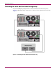
Identifying the node components
Figure 1 lists the node components, including the location of the initiator and target ports:
■ Dual–port Gigabit Ethernet card (1)
— Port A—MirrorLink
— Port B—InterLink
■ Four–port HBA card (2)
— Port 0—Target 2
— Port 1—Target 3
— Port 2—Initiator 2
— Port 3—Initiator 3
■ Four–port HBA card (3)
— Port 0—Target 4
— Port 1—Target 5
— Port 2—Initiator 4
— Port 3—Initiator 5
■ Four–port HBA card (4)
— Port 0—Target 0
— Port 1—Target 1
— Port 2—Initiator 0 (shared disk connection)
— Port 3—Initiator 1
■ USB connectors (5)
■ Unit ID switch and LED (6)
■ Auxiliary VHDCI SCSI blank (7)
■ Serial connector A (8)
■ Mouse connector (9)
■ Keyboard connector (10)
■ Serial connector B (11)
■ Primary hot-pluggable power supply (12)
■ Video connector (13)
■ Parallel connector (14)
■ iLO management port (15)
■ Ethernet 10/100/1000 port (16)
■ VHDCI SCSI port 2 connector (17)
■ Redundant hot-pluggable power supply (18)