A Proposal for New Presentations Intelligent Projector User’s Manual iP-25E English Deutsch Français Español Italiano
Thank you for your purchase of an AVIO product. Please read this manual carefully in order to use the projector properly. After reading this, please keep it in a safe place together with the warranty sheet. Features of the iP-25E • Very versatile five-in-one projector. A projector for the multimedia age. 1. Projection of documents, catalogs, and other printed materials. Printed materials can be projected directly without the creation of OHP film. 2.
Safety Precautions WARNING ● If a fault occurs: • If you detect smoke, or a strange smell or sound, immediately disconnect the power cable. It is dangerous to continue using the projector after a fault occurs. Return the projector to the dealer where it was purchased for repair. ● Avoid placing the projector near dangerous substances. • Make sure that no metallic or flammable material can get into the projector through the air vents.
Safety Precautions CAUTION • Installation • Avoid installing the projector in places where it may be exposed to: - Strong vibrations - Soot or steam - Direct sunlight or near a heater (35°C/95°F or higher) - High humidity or dust - Extreme cold (0°C/32°F or lower) - Strong magnetic or electric field generated from a nearby appliance - Wobbling on an unstable surface • Do not block the air vents. • Do not block the air vents with cloth or an object.
Safety Precautions • Lamp implosion • A DC type Super High pressure lamp is used in this projector and it is rare for the lamp to explode during use. The unit is also designed to forcibly turn off the lamp because there is a high possibility that the lamp will break if it is used beyond the lamp usage of 2000 hours (Refer to pages E-42 and E-44). Note the following things • A sound occurs because the internal pressure of the Super High pressure lamp gets extremely high.
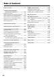
Table of Contents Safety Precautions ................................................. E-3 A Check of the Supplied Items and the Names of the Parts .............................. E-7 Supplied Parts Check ............................................... E-7 Names and Functions of the Parts (Projector) ......... E-8 Names and Functions of the Parts (Input Connectors) ........... E-10 Names and Functions of the Parts (Operation Panel) ............ E-11 Names and Functions of the Parts (Remote Control) .........
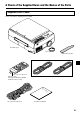
A Check of the Supplied Items and the Names of the Parts Supplied Parts Check Please check that the supplied parts are included. iP-25E Projector Lens cap Replacement air filter Pull out the sheet before use.
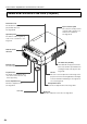
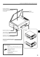
A Check of the Supplied Items and the Names of the Parts Names and Functions of the Parts (Projector) Document cover The document or printed material to be read is placed under this cover. Input connector panel The connectors for the personal computer, video, and other con- See Page E-30. nections are located here. See Page E-10. Operation panel The buttons used for regular operation are located here. See Page E-11.
A Check of the Supplied Items and the Names of the Parts Document reading area The document or printed material that you wish to project in the OHP mode is placed here. See Page E-30. Speaker (2 W, monaural) Remote control IR sensor Handle Theft prevention lock Please see the Note below. Power input connector Plug in the power cable here. See Page E-21. Lamp unit cover (Underneath projector) The projection lamp unit is located inside. See Page E-42.
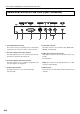
A Check of the Supplied Items and the Names of the Parts Names and Functions of the Parts (Input Connectors) 1 2 3 1. Test (maintenance) connector This special connector is used at the time of maintenance and factory tests. It cannot be used for other connections. 2. Personal computer audio input connector This audio input connector is for use with the personal computer (Stereo supported). See Page E-16. 4 5 6 7 5.
A Check of the Supplied Items and the Names of the Parts Names and Functions of the Parts (Operation Panel) 4 3 2 5 1 6 7 1. POWER Button Switches the power of the projector on or off (standby mode). • Only this button is effective when the projection lamp is off. See Page E-21. 2. ON/STANDBY LED Lit red during standby and lit green when the projection lamp is on. See Page E-21. 3. LAMP/COVER LED Lit green during projection. Lit red when the air filter or lamp unit cover is not in place.
A Check of the Supplied Items and the Names of the Parts Names and Functions of the Parts (Remote Control) 5. ZOOM Buttons These buttons adjust the magnification of the projection screen. 1 2 3 See Page E-24. 6. MENU Button Switches on or off the display of the menu screen. 4 See Page E-32. 5 7 6 9 8 11 10 7. SCROLL Buttons Sets the selection of the item or the adjustment value at the menu screen. Moves the zoom position during a zoom display.
A Check of the Supplied Items and the Names of the Parts Operation of the Remote Control • Please use the remote control within a range of about 7 m from the remote control IR sensor of the projector (located at both the front and rear) and within an angle of 10 degrees to the left and 10 degrees to the right. Note that this distance may be shorter depending on battery consumption.
Procedure Up to Projection 1 Consideration of placement location and screen size Determine the screen and projector setup location. Set the projector on a strong and stable, level platform. See Page E-15 for information about the projection distance and screen size. 2 Connections with input equipment Connect your personal computer/video equipment.
Projection Distance and Screen Size Please use the following diagrams to determine the screen display size and the type of screen required for any given projector location. Projection distances that will be in focus will be 1.3 m (4.3 feet) to 11.3 m (37.0 feet) from the front of the lens. Please arrange the setup within this range. (inch) 350 300 300 250 Wide 200 200 150 150 100 100 Tele 80 60 40 150 100 80 50 200 60 40 30 0 0.0 0.0 2.0 6.6 4.0 13.1 6.0 19.7 8.0 26.2 10.0 32.8 12.
Connections with the Personal Computer Connection Precautions • To protect this projector and the equipment to be connected, switch off the power of each unit before making connections. • Please read the various equipment instruction manuals for information about the connection of the CAUTION equipment and the method of use. • When connection is made with a notebook computer and the image is displayed on the LCD screen of the notebook computer, a proper display might not be obtained on projection screen.
Connections with the Personal Computer Connecting Macintosh Computers • Attach the supplied (RGB+USB) cable if when the monitor output is a VGA port (mini D-SUB 15-pin). • An optional Apple video adapter cable is required when the monitor output is a video port or DVI port. • Please do not make a USB connection because iP Viewer does not support the Macintosh. Personal Computer Input Connector Personal Computer Input Connector The personal computer input connector uses a 15-pin mini D-SUB type connector.
Connections with the Personal Computer When the Image of the Personal Computer Screen Is Not Projected Please check the matters described below when the image of the personal computer is not projected or when there is projection but the image is not correct. ● The image is not projected When the external output signal from the personal computer is not input to the iP-25E, "No signal being input" is displayed on the display screen of the iP-25E. Should this occur, please check the following matters.
Connections with the Personal Computer Table of Supported Input Signals (Personal Computer Video Input Connector) Signals indicated with a “Yes” are supported. Note that depending on the model of personal computer, please perform the screen adjustment of the "Image adjustment" → "Sync adjustment" menu if flickering or bleeding appear on the projection screen. → See Page E-37 Resolution Horizontal Frequency Vertical Frequency (Horizontal ⳯ Vertical) (kHz) (Hz) NTSC RGB – – 15.
Connections with Video Equipment The video of a video tape deck or DVD player is projected onto a large screen. iP-25E Projector side connector panel To the video output connector Video deck To the audio output connectors DVD player NOTE: • When both Video and S-video connections have been made, S-video will be given priority for display. • When a video signal have a lot of noise, the image may be displayed in monochrome.
Connection of the Power Cable and On/Off Switching Switch On the Power 1 Connect the power cable The projector will enter the standby mode and the ON/STANDBY LED will light in red. To wall outlet. 2 Press the POWER button ( ) Operation with the Remote Control Operation with the Projector The fan will turn, the lamp will light, and the ON/STANDBY LED will light in green. The LAMP/COVER LED will light in green. • If the LED lights in red after the POWER button is pressed, projector trouble is indicated.
Adjustment of the Projection Image Adjusting the Projection Image Adjust the projection image to the screen. Right angle • When the image is shifted to the left or right, move the projector horizontally. (Align the center of the screen with the center of the projector lens.) • When the image is shifted up or down, use the tilt foot to adjust the projector vertically. • When the image is slanted, turn the left or right tilt foot to adjust.
Regular Operation This section describes the use of direct operation using the projector and remote control buttons. Please see the items on Page E-32 "Menu Operation Method" and Page E-35 "Menu Description" for information about operation using the menu. Select the Input When the power of the projector is switched on, the input selection (OHP / PC / VIDEO) icon is displayed. Operation with the Projector Select the input using the INPUT SELECT buttons.
Regular Operation To view the portion that has been cut off Operation with the Projector Press the SCROLL (왖왔) buttons and scroll the projection image up or down. Operation with the Remote Control Press the SCROLL (왖왔) buttons and scroll the projection image up or down. A B C • Pressing the ZOOM (–) button permits display of a large portion within the reading range of the vertical display. The undisplayed portion can be displayed with the SCROLL (왖왔) buttons.
Regular Operation Moving the Screen Movement is possible in 4 directions (up, down, left, and right). Operation with the Projector Press the SCROLL (왖왔왗왘) buttons. Operation with the Remote Control Press the SCROLL (왖왔왗왘) buttons. Adjusting the Brightness To change the brightness, perform a manual adjustment using the method described below. Operation with the Projector Adjust using the BRIGHTNESS ( ) buttons.
Regular Operation Capturing the Projection Image Effective Only with OHP Input / Still Image Display During OHP Input Operation with the Projector Pressing the FREEZE/CAPTURE button captures the OHP image that is currently being projected and saves it as an Press the FREEZE/CAPTURE button. image file. Captured images are automatically stored in the internal memory as OHP history images for up to 32 pages. The projected image will become a frozen (fixed) display.
Regular Operation Cancelling the Still Image Display Operation with the Projector Press the FREEZE OFF button. Operation with the Remote Control Press the FREEZE OFF button. 32 NOTE: The FREEZE LED will go off when the still image display is cancelled. 32 Viewing OHP History Images Viewing captured images Operation with the Projector A list display of captured images is not available from 1 2 3 4 the operation panel of the projector.
Regular Operation Transferring Captured Images When connection is made with a USB cable, history images can be transferred to the per- Operation with the Projector Press the TRANSFER button. sonal computer. Please switch the input to "PC" and press the data TRANSFER button. NOTE: Please see the attached “iP Viewer Program Quick Reference” or the “iP Viewer Software Program Operating Instructions” for information about the iP Viewer operation method.
Regular Operation Displaying the Pointer This operation displays the pointer in the currently projected image. Operation with the Projector The ability to turn on and turn off the pointer is not available from the operation panel of the projector. Operation with the Remote Control Press the POINTER/SET button. One more press of the POINTER/SET button while the pointer is displayed will turn off the pointer display. Moving the Pointer Operation with the Projector Press the SCROLL (왖왔왗왘) buttons.
Method of OHP Operation Attaching the Document Cover The mounting orientation of the document cover can be changed to the opposite direction in accordance with the circumstances circumstances. NOTE: When removing the document cover, lift the cover by both hands and remove it. Preparation of the Projection Document The document (printed material) that is to be projected is placed on the projector as illustrated in the diagram below and the document cover is closed.
Menu Configuration The adjustment/setting items and content will differ depending on the input selection and the permitted information will be displayed on the menu for that input mode.
Menu Operation Method Names and Functions of the Buttons Used in Menu Operation SCROLL 왖왔왗왘 Buttons Used in the selection of menu names and item names, and to set and ad- POINTER/SET Button Used to finalize a setting after just item contents. making the setting or adjustment. MENU Button Used to display a menu and to close a menu. Names and Functions of the Menu Parts Menu tab Switches to the various menus when selected.
Menu Operation Method Method of Menu Operation This section describes the actual operation method. Adjustment of [Keystone] using the remote control is provided as an example. 1 Press the MENU button and display the menu 2 Select [Settings] with the SCROLL 왗왘 buttons Each press of the SCROLL 왘 button switches the menu one step in the sequence of [Pointer • Screen] → [Image adjustment] → [Settings], and each press of the SCROLL 왗 button causes a return in the opposite direction.
Menu Operation Method 4 Press the POINTER/SET Button Switches the menu to the sub menu (i.e., the Keystone adjustment menu). 5 Make the adjustment with the SCROLL 왗왘 buttons while checking the projection image SCROLL 왗 button: Each press causes the numerical value to decrease. (The lower portion of the projection im- SCROLL 왘 button: age becomes narrower.) Each press causes the numerical value to increase. (The upper portion of the projection image becomes narrower.
Menu Description Pntr setting This selects the shape, color, and size of the pointer. 䢇 Pointer shape ................. Selects the shape of the pointer from 2 types. 䢇 Pointer color ................... Selects the color of the pointer from amongst 3 types (i.e., red, white, and blue). 䢇 Pointer size .................... The size of the pointer can be changed in 3 levels. 䢇 Mute mode ..................... Sets the image that will be displayed at the time of screen deletion.
Menu Description The following items will be displayed only during the projection of the page that was selected from the OHP history list. 䢇 Back page in history ...... Switches to the history screen that was stored before the currently projected history screen. 䢇 Next page in history ....... Switches to the history screen that was stored immediately after the currently projected history screen. 䢇 Save as wallpaper .......... A confirmation screen will be displayed.
Menu Description Sub menu: Sync adjustment 䢇 Clock .............................. Adjusts the horizontal size of the projected image in the range of -50 to 50. 䢇 Phase ............................. Adjusts the noise/flickering of the projected image in the range of -50 to 50. 䢇 Horizontal ....................... Adjusts the horizontal position of the projected image in the range of -50 to 50. 䢇 Vertical ...........................
Menu Description Settings This performs settings related to the projector unit or while the projector is in use. 䢇 Lamp usage time ........... Displays the usage time of the lamp. "Replacement of the Lamp Unit" → See Page E-42 䢇 Input signal ..................... The name of the currently selected input is displayed. Setting Items 䢇 Keystone ........................ Performs keystone correction of the projection image.
Menu Description 䢇 Projection mode ............. Selects the projection system of the projector from between Front (front projection) and Rear (rear projection). 䢇 Economy mode .............. ON (Economy mode): The brightness of the lamp will be approximately 80%. The lamp service life will be extended. OFF (High brightness mode): The brightness of the lamp will be 100%. There will be a bright screen.
Maintenance Fault Protection The projector is equipped with a built-in protection circuit to prevent fire and breakdown due to faults. When the LAMP/COVER LED lights in red 䡬 Measures to be taken 1. Disconnect the power plug from the outlet. 2. Properly install the air filter. See "Air Filter Cleaning" on Page E-45. 3. Properly install the lamp unit cover. See "Replacement of the Lamp Unit" on Page E-42. When the TEMP LED flashes or lights steadily 䡬 Measures to be taken 1.
Maintenance When the power has failed (When all the LED go off with the power ON) 䢇 Measures to be taken 1. Disconnect the power plug from the outlet. 2. Check the following matters and perform the countermeasure properly. Is the ambient temperature in excess of 35°C (95°F)? Please use the projector in an operation ambient temperature of 0°C (32°F) to 35°C (95°F). Are the ventilation vents blocked? Rearrange the setup location of the projector and separate the projector from surrounding objects.
Maintenance Replacement of the Lamp Unit Guidelines for the replacement of the projection lamp used in this projector are described below. (The time may be shorter depending on usage conditions.) When the usage time exceeds the time described below, the likelihood of rupture increases, the projector will be forced to turn off the projection lamp. Guideline for lamp replacement 䢇 Usage time when used only in the high brightness mode* .......... 1900 hours 䢇 Usage time when used only in the economy mode ...
Maintenance Lamp Unit Replacement Procedure To prevent burns, wait one hour or longer after the lamp has been switched off before performing the following procedure. Positioning protrusions 1 Remove the lamp unit cover Using a minus screwdriver, loosen the screws of the lamp unit cover, pull in the direction of the arrow, and remove the cover. 2 Loosen the mounting screws of the lamp unit Using a minus screwdriver, loosen the 2 screws of the lamp unit.
Maintenance 5 Reset the lamp usage time Please perform the operation indicated below in the standby mode (*). Operation with the Projector Press these buttons in order while pressing the but- ton. Operation with the Remote Control Resetting of the lamp usage time cannot be performed with the remote control. The LAMP/COVER LED will flash green following this and projection will start. * The power plug is plugged into a power outlet and only the ON/STANDBY LED is lit red.
Maintenance Cleaning the Air Filter The air filter is an important part that prevents the intrusion of dust onto the optical parts and other parts inside the projector. When the air filter becomes blocked, the internal temperature will rise and the rotation of the fan will also increase leading to a reduction of the service life or causing breakdown. In view of this, the air filter should be cleaned regularly (about once a month, when the projector is used 4 hours per day).
Troubleshooting When you think the projector may be out of order, please first check the following matters before requesting repair. Symptom Power does not come on Please check this • Is the power cable connected? Projection lamp does not light • Is the lamp burned out? Reference page E-21 E-42 • Is the lamp unit cover installed? E-43 • Is the air filter installed? E-45 • Is the internal temperature high? If so, the lamp will not light E-40 to protect the projector from damage.
Repair Service Repair Service Procedure • Before asking for repair service, check the Troubleshooting section on page E-46 once more. If this check confirms a problem, contact the dealer where you bought the product. • When asking for repair service, provide your dealer with the following information: Description of the problem (as many details as possible) Date of purchase Your Name Your Address Telephone number Product name and model No.
Specifications Model Name Type Main Part Specification LCD Panel iP-25 3 primary Color LCD Shutter Projection Type Size 0.7 inches x 3 Panels, Aspect Ratio 4:3 Drive System Poly Silicon TFT Active Matrix with Micro Lens Array Number of Pixels 786,432 pixels (1,024 x 768 dots)⳯3 Arrangement Stripe Projection Lens Manual Zoom: 1 to 1.2x Optical Source 180W Super High-pressure Mercury Lamp Image Size 30-300 inches diagonal (projection distance 1.3 to 11.