
Technical data


Physical Configuration Tool
With T0682 H02 AAN and later, the OSM Service Connection provides the Physical Configuration
Tool. You can use it to create and save a physical display of the racks in which your modular
NS-series system or NonStop BladeSystem resides.
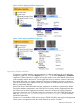
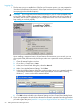
To launch the tool, within the OSM Service Connection, select Physical Configuration Tool from
the Tools menu on the OSM menu bar (see Figure 12).
Figure 12 Launching the Physical Configuration Tool
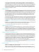
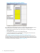
When first launched, the Physical Configuration Tool displays whatever OSM knows about the
current physical configuration of your system (see Figure 13 (page 56)). This information is based
solely on Rack Name and Rack Offset values assigned by OSM users through individual Set Physical
Location actions on modular components. The Set Physical Location action is available for Blade
Elements, FCDMs, IOAM Enclosures, VIO Modules (which is how OSM represents VIO enclosures),
Processor Switch Modules, and Processor Components (LSUs). The problems with this information
include:
• Components not assigned Rack Name and Rack Offset values are displayed in the
Unconfigured FRUs pane rather than in the Configured Racks pane (the upper left pane, as
illustrated in Figure 13).
• Components given even slightly overlapping Rack Offset values are displayed in the Incorrectly
Configured FRUs pane (the lower left pane, as illustrated in Figure 13). Their locations in the
Configured Racks pane are displayed as yellow, unlabeled areas (also illustrated in Figure 13).
• If you moved a component but did not use the action to update it, it continues to be displayed
in the old (incorrect) location.
• If Rack Names are not precise. For example, if one FCDM is designated as Rack 1, another
in the same rack is designated as rack 01, the Physical Configuration Tool displays those as
two separate racks.
OSM Service Connection 55