OSM Configuration Guide HP Part Number: 527273-040 Published: February 2014 Edition: J06.03 and subsequent J-series RVUs and H06.
© Copyright 2014 Hewlett-Packard Development Company, L.P. Legal Notice Confidential computer software. Valid license from HP required for possession, use or copying. Consistent with FAR 12.211 and 12.212, Commercial Computer Software, Computer Software Documentation, and Technical Data for Commercial Items are licensed to the U.S. Government under vendor’s standard commercial license. The information contained herein is subject to change without notice.
Contents About This Document.....................................................................................6 Supported Release Version Updates (RVUs)..................................................................................6 Intended Audience....................................................................................................................6 New and Changed Information in This Edition..............................................................................
OSM Upgrade Considerations.................................................................................................33 Starting OSM Persistent Processes.............................................................................................33 Other OSM Server Processes...................................................................................................33 $SYSTEM.SYSnn.APPRVD....................................................................................................
Miscellaneous Changes.................................................................................................57 Establishing an OSM Service Connection Session..................................................................57 Method 1: Using Home Page Bookmarks..........................................................................57 Method 2: Without Client Installation or Bookmarks...........................................................59 Logging On..........................................
About This Document This guide introduces the HP NonStop™ Open System Management (OSM) Interface, the required system management tool for HP Integrity NonStop NS-series servers and HP Integrity NonStop BladeSystems. Beginning with T0682 H02 ABI, the OSM server supports both H-series and J-series RVUs, while a separate version continues to support G-series. Likewise, this manual describes OSM for H-series and J-series; a separate version describes OSM for G-series.
OSM changes for H06.26/J06.15 OSM T0682 H02 ADD added support for: • Added the following new section: “Configuring Non-Default Users” (page 71). • Updated note in following sections regarding the configuration of non-default users: “OSM Low-Level Link” (page 63), “NonStop Maintenance LAN DHCP DNS Configuration Wizard” (page 70), and “Down System CLIM Firmware Update Tool” (page 71).
• The “NonStop Maintenance LAN DHCP DNS Configuration Wizard” replaces the CLIM Boot Service Configuration Wizard in OSM Console Tools. • The “Down System CLIM Firmware Update Tool” is added to OSM Console Tools. Related Information Document Location OSM Service Connection Available as online help from within the OSM Service Connection; also available online at User's Guide http://www.hp.
1 Introduction to OSM The NonStop Open System Management (OSM) suite of products are the required system management tools for all NonStop NS-series servers and NonStop BladeSystems; TSM is not supported on H-series or J-series. Primary Goals • Provide a system management tool suite to support Integrity NonStop NS-series servers and NonStop BladeSystems. • Replace TSM on S-series as well, providing an architecture to improve scalability and performance and overcome other limitations of TSM.
interfaces of the climcmd tool and SCF. For more information, see the NonStop I/O Essentials Installation and Quick Start Guide. • NonStop Software Essentials – a software installation and management tool for NonStop servers, providing a replacement for the DSM/SCM Planner Interface and certain Host Maintenance Interface functions that is more secure, easier to use, and overcomes other shortcomings of DSM/SCM. For more information, see the NonStop Software Essentials Installation and Quick Start Guide.
2 Preparing for OSM This section describes how to prepare for migration to OSM software, including: • “System Console Requirements” (page 11) • “Server Software Requirements” (page 11) • “Preparing the Hardware and LAN Environment” (page 12) System Console Requirements NonStop system consoles used to manage NonStop NS-series servers or NonStop BladeSystems must be running Microsoft Windows Server 2003 or Windows Server 2008, as configured and shipped by HP.
Preparing the Hardware and LAN Environment While most OSM functionality should be used only on a dedicated service LAN, some components can be used on a nondedicated operations LAN. To use OSM on a nondedicated operations LAN, see “Configuring Additional TCP/IP Processes for OSM Connectivity” (page 18). For more information on preparing and configuring your NonStop environment, see the appropriate planning guide and hardware installation manual for your NonStop NS-series server or NonStop BladeSystem.
3 OSM Server-Based Components This section provides information about OSM server-based components: • “OSM Server-Based SPR” (page 13) • “Ports Used by OSM” (page 13) • “Adding OSM Process Files to TACLCSTM and CMON Exceptions” (page 14) • “Optional OSM Configuration” (page 15) • “OSM Upgrade Considerations” (page 33) • “Starting OSM Persistent Processes” (page 33) • “Other OSM Server Processes” (page 33) • “OSM Server Files” (page 35) OSM Server-Based SPR For both H-series and J-series RVUs,
Adding OSM Process Files to TACLCSTM and CMON Exceptions A TACLCSTM script which expects direct human interaction will interfere with certain OSM actions and activities. Some OSM processes start TACLs which are non-interactive, with the user ID of the OSM Service Connection session, or with the SUPER.SUPER ID for unattended OSM operations. The most likely issues to be noticed without previous planning occur for a shared service user id. Issues are also possible for the SUPER.SUPER user ID.
... #pop ancestor programfile Refer to the Guardian Programmer’s Guide for more information about CMON. Optional OSM Configuration It is not necessary to create a configuration file to use OSM with the default settings.
3. When you start OSM server processes, configuration settings are read from the OSMCONF file if one exists in that location. If not, OSM default settings are used. To change your settings after OSM is running, select Reload Configuration Settings from the OSM Service Connection Tools menu. To complete this operation, you are instructed to restart the $ZOSM and $ZOEV processes.
Example: Disabling all Alarm Dial-outs Except a Specified Alarm To enable the dial-out of a specified alarm (for example, Too Many Router Port Errors) but disable the dial-outs of all other alarms, add the following lines to the OSMCONF file: disableAllDialout = YES enableDialout = Too Many Router Port Errors Example: Disabling all Alarm Dial-outs Except an Alarm with a Specified Prefix To enable the dial-out of an alarm (for example, Loss of ServerNet Fabric X for Processor 3), with a specified prefix (fo
Source stack name TCP/IP process name to use. The value of the stack entries in the OSMCONF file (see “Configuring Additional TCP/IP Processes for OSM Connectivity” (page 18)) should not be more restricted than this one. Source IP IP address that OSM will bind to when sending the indication. The values of the stack entries in the OSMCONF file (see “Configuring Additional TCP/IP Processes for OSM Connectivity” (page 18)) should be chosen to allow use of the desired Source IP entry.
NOTE: You can use the stack parameter with syntax : to control the specific server IP addresses used by the OSM Service Connection, HP SIM, or Insight Remote Support Advanced. The OSM server will not allow connections to other IP addresses. For OSM Service Connection sessions, this parameter affects both the URLs allowed for the initial connection to the OSM Server, and additional TCP/IP connections opened afterwards for realtime updates and fault tolerance.
Enabling Enhanced Redundant Power Scrub For T0682 H02 ABE and later, an enhanced version of the Redundant Power Scrub test is available for legacy S-series enclosures. It provides independent battery testing and an extended load test for the bulk power supplies. NOTE: With this new version of Redundant Power Scrub, the action can take up to 25 minutes to complete. The new battery scrub is significantly enhanced in its ability to detect weak or failed batteries.
Configuring Automatic Data Collection For T0682H02 AAM and later, OSM has enhanced automatic data collection capabilities. If enabled, OSM automatically collects diagnostic data whenever a hardware failure causes a Problem Incident Report (IR) to be created. Automatic data collection is enabled through the Enable/Disable Automation of Data Collection action, located under the system object in the OSM Service Connection.
For more information on what suppression means, including the difference between permanent and temporary suppression, see “Suppressing Alarms” (page 52) and “Suppressing Problem Attributes” (page 51). To disable suppression persistence in T0682 H02 ABX and later, put the following parameter into your OSMCONF file: SuppressionPersistenceAcrossOSMRestart = OFF To make changes to your OSMCONF file take effect, see “Creating and Using an OSMCONF File” (page 15).
The default value is 0.4,0.10,0.5. The value represents three different values separated by commas. (Other combinations involving multiple values may be specified in the same comma separated fashion.) The allowed values are listed below, followed by a description of each: • 0.4 – RSA-key-exchange + RC4-128-bit encryption and MD5 (RC4-MD5) • 0.5 – RSA-key-exchange + RC4-128-bit encryption and SHA (RC4-SHA) • 0.10 – RSA-key-exchange + 3-DES encryption and SHA (DES-CBC3-SHA) • 0.
[ ca ] default_ca= CA_default [ CA_default ] database= index.txt serial= serial.
The total number of IP addresses visible with SCF INFO SUBNET .* could be larger than the number of IP addresses a Certificate Authority allows in the SAN field. To restrict the IP addresses used by the OSM Service Connection, you must use the following specialized syntax for the OSMCONF stack parameter: stack = : A similar syntax holds for the evtstack parameter, which affects the OSM Event Viewer.
• CACERTS = • SERVKEY = • SERVKEYPASS = On the PC side, the certificate will be trusted by default if: • The certificate is not self-signed. • The certificate is valid (and not expired). • The certificate is signed by a trusted CA. • If the certificate has a SAN, the server’s address matches one of the entries in the SAN. • If the certificate does not have a SAN, the server’s address matches the Subject CN.
The v3_req_ext_SERVER section in the config.txt file specifies the Subject Alternative Name (SAN) to be added when a certificate is issued. 6. Convert the key to PKCS#8 DER format. openssl pkcs8 -topk8 -outform DER -in server.key.pem -out server.key 7. Sign the new CSR with the CA key. openssl ca -days 365 -policy policy_anything -keyfile ca.key.pem -cert ca.cer.pem -in server.csr -out server.cer.pem -config config.txt -extensions verisign_SERVER The verisign_SERVER section in the config.
nn is the number in minutes before an idle event viewer session is deleted and cannot be accessed again. This parameter has the same value options as the EvtMgr_Session_Expiration_Time parameter. However, as noted above, it must be set higher than the expiration parameter in order to have the ability to log on again to an expired session before it is deleted permanently.
Workaround: Launched independently of the OSM Service Connection, the OSM Event Viewer is already compatible with NAT and no additional configuration is necessary. The workaround for accessing the web-based management applications is also to launch them directly from an Internet browser and not through the OSM Service Connection.
qualified because if not specified, OSM will only look in the default subvolume of $system.zservice, which is not recommended for the placement of such script files. Example: SHUTDOWN_SCRIPT_NAME = $SYSTEM.SYS00.SYSHTDWN SHUTDOWN_SCRIPT_TIME = nn nn is the time, in seconds, that the script is to be executed before the end of the configured ride-through period.
== Add $ZOSM process to SCF database and issue start command @ ABORT PROCESS $ZZKRN.#OSM-APPSRVR @ DELAY 1 @ DELETE PROCESS $ZZKRN.#OSM-APPSRVR @ ADD PROCESS $ZZKRN.#OSM-APPSRVR, AUTORESTART 10, CPU FIRSTOF [listProcessors], DEFAULTVOL $SYSTEM.ZSERVICE, HIGHPIN ON, HOMETERM $ZHOME, NAME $ZOSM, PRIORITY 150, PROGRAM $SYSTEM.SYSTEM.APPSRVR, OUTFILE $ZHOME, & & & & & & & & & & STARTUPMSG "cpu-list cpu-list, security NCNC", & STARTMODE APPLICATION @ START PROCESS $ZZKRN.
SCF abort process $zzkrn.#osm-cimom 3. Use the following command to alter and overwrite the startup message (STARTUPMSG) for the process, re-creating any entries from the current file that you wish to preserve, while specifying the desired security levels for the process using the rwep (Read, Write, Execute, Purge) format illustrated below: SCF alter process $zzkrn.#osm-cimom, startupmessage "BackupCpu | cpu-list cpu-list, security rwep" 4. Start the process: SCF start process $zzkrn.#osm-cimom 5.
To make changes to your OSMCONF file take effect, see “Creating and Using an OSMCONF File” (page 15). OSM Upgrade Considerations To help ensure accurate alarm reporting in OSM, when upgrading to a new OSM servers SPR (or falling back to a previous version), you should purge the IAREPO file from $SYSTEM.ZSERVICE.
$SYSTEM.SYSnn.APPRVD Launched by $ZOSM, Applet Providers are responsible for serving client files. The maximum number that can run simultaneously is eight. $SYSTEM.SYSnn.EMSDIST* EMS Event Distributor used for Auto Reallocate. Monitors medium error events generated by disk driver and starts the automatic sector reallocation process ($ZARS) Process name: $ZRD9 SCF process: $ZZKRN.#ROUTING-DIST * Not delivered as part of OSM, but rather an existing process used by OSM. $SYSTEM.SYSnn.
$SYSTEM.SYSnn.RALPRVD and $SYSTEM.SYSnn.RALPRVNP Launched by $ZCMOM, these Resource Access Layer Providers are responsible for: • Interacting with SP and subsystems such as Storage, SLSA, etc., to gather attributes and states for system resources • Executing all actions on OSM objects • Triggering Incident Analysis to generate and clear alarms RALPRVD is used for initial discovery, initial incident analysis, event processing and all action execution that require a super-group user.
$SYSTEM.ZOSM File Name Description ADDTCPIP Script to configure $ZTCP0/1 into the persistence manager using INIT0/1. ADDTOSCF Script to configure OSM persistent processes into the persistence manager. ALTERIP Script to restart $ZTCP0/1 using CTCPIP0/1. CTCPIP0/1 Script to configure $ZTCP0/1. INIT0/1 Script to bring up $ZTCP0/1 with the factory default IP address (set by ADDTCPIP). LOGALTIP Trace log generated by ALTERIP LOGSCF Trace log generated by ADDTOSCF.
ZTRC File containing pointer to the current ZTRCn file. Created and maintained by CIMOM. ZTRCn Text files containing user trace logs (1-5). Created and maintained by CIMOM. Maximum size: 0.25 MB. ZZSKnnnn $ZLOG alternate key file. ZZSVnnnn $ZLOG data files.
4 OSM and Other HP Client-Based Components OSM Client-Based Applications OSM client-based components are installed on new system console shipments and also delivered by an OSM installer on the HP NonStop System Console (NSC) Installer DVD. The NSC DVD also delivers all other client software required for managing and servicing all NonStop systems. (Unlike OSM server, which has one version for G-series and another for H- and J-series, the client-based software is the same for all three RVU threads.
Other HP Client-Based Tools HP Systems Insight Manager (SIM) HP Systems Insight Manager (SIM), which provides infrastructure management for all HP servers and storage, now supports the NonStop platform via a Web-Based Enterprise Management (WBEM) provided by OSM. HP SIM is capable of discovering NonStop systems, displaying and forwarding alarms generated by OSM, and collecting system and device data.
OSM has been enhanced to allow a NonStop system to be powered down gracefully from Insight Control Power Management. OSM also allows Insight Control Power Management to display CPU utilization data for NonStop systems as it does for other platforms. The Insight Control Power Management installer is included on the HP Insight Control for NonStop DVD that ships along with the NonStop System Console Installer DVD.
6. 7. 8. 9. 10. 11. 12. 13. In the Options dialog box click Apply, then OK. Select File, then Connect. There will be two windows on the screen, Local Path and Host Path, one will show folders on the PC, the other will show the files in the default volume on the host. Select in the Options dialog box, Transfer Type of ASCII or binary file. Enter the PC folder name, or use the buttons to select the folder for the Local Path. Enter the \.$. for the Host Path.
5 Getting Started With OSM Applications This section introduces the OSM client interfaces, providing the following information for each application: • Overview of basic purpose and functionality • Description of enhancements and functional differences between OSM and TSM (for server-side differences, see Section 3, OSM Server-Based Components) NOTE: While OSM is required for NS-series servers and NonStop BladeSystems (TSM does not support them), this section compares OSM applications to their TSM predece
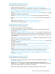
Figure 1 Management Window for the OSM Service Connection OSM-Specific Interface Differences This list describes some of the changes between the visual display in the OSM Service Connection Management window and that of the TSM Service Application: • There is no longer a tab to switch between System and Cluster views in the tree pane. Both system and cluster hierarchies appear in the same tree pane view.
The following standard Internet Explorer functionality can be used: • Find (Edit menu) works in some, but not all OSM panes. It works in the details pane, Inventory view (place your cursor to the left or right of the Save button), and most secondary dialogs; but does not work in the tree pane or Physical view. • Print (File menu) works for the selected pane, but the Print dialog takes up to one minute to appear (during which time you cannot access the OSM window).
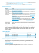
Figure 2 Multi-Resource Actions Dialog Box: SWAN CLIP Object Selected In Figure 3, a continuation of the SWAN CLIP example, the Stop action has been selected from the list of available actions for the CLIP object. Using the Add or Add All buttons, select and move only the CLIPs you want to perform the action on to the blank list that appeared below the Add and Add All buttons. (The red lines in Figure 3 indicate where you can click and drag to resize the areas that these lines divide.
Figure 3 Multi-Resource Actions Dialog Box: Performing a SWAN CLIP Action The Multi-Resource Actions dialog box has a new look from G-series releases. Also, starting with H06.
4. Click Save to save this customized “Resource View.” To use this view in the future, choose it (by the name you gave it) from Multi-Resource Actions dialog box Configuration drop-down menu (instead of “default”). The next time you log on to the OSM Service Connection, it will also appear in the Resource Views drop-down menu, located under the Display menu.
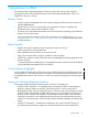
Figure 5 Problem Summary Dialog Box Logical Status Information The Logical Status icon and view are included in T0682 AAM and later. The Logical Status icon, displayed next to the System Status icon in the View pane toolbar (see Figure 6), gives you a quick indicator of the status of the components that are included in the Logical Status view – those being all disks, logical processors, LIFs, and SWAN paths on the system.
Figure 7 Logical Status View System Status Window If you are monitoring several systems simultaneously, OSM offers a more convenient tracking method of systems than resizing all of your Management windows. Select System Status from the Summary menu to create a small, separate window displaying just the system icon for each system. You can then minimize (but not close) all Management windows and track system health by the color of the system icon.
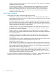
Figure 9 Propagation of Subcomponent State Problems Suppressing Alarms, Attributes, and Problem IRs Another feature in OSM is the ability to suppress alarms, attributes, and problem IRs. You can acknowledge a known problem and keep it from propagating problem conditions all the way up to the system icon (as Figure 10 illustrates).
Figure 10 Before Applying Attribute Suppression Figure 11 After Applying Attribute Suppression Suppressing Problem Attributes To suppress a problem attribute, select the attribute (in either the Attributes tab or the Attributes dialog box), right-click, and select Suppress (see Figure 10), the either Temporary or Permanent suppression. Select temporary to suppress as long the specific value of the attribute (Hard Down, in this example) remains the same.
To unsuppress a problem attribute, select the attribute, right-click, and select Unsuppress. You cannot suppress a Service State or Subcomponent State attribute. A Service State attribute of something other than OK is caused by one or more alarms on the resource. You must suppress the alarm to acknowledge (or clear) the Service State.
time by just performing a Rediscover for the object you are concerned with at the time (and individual group or ServerNet adapter, for example). Refresh refers to OSM updating the attribute values displayed in the OSM Service Connection interface. Reanalyze refers to the running of OSM incident analysis, which checks EMS event messages and creates alarms in OSM if certain conditions exist.
3. In the Load Snapshot File dialog box, navigate to the snapshot file you want to view and click Open. The snapshot looks like a regular OSM Service Connection session, except that “(SNAPSHOT)” appears in the title bar and the system icon in the view pane (\STAR3 in this example) is gray instead of yellow or green, which is used to indicate status in active OSM Service Connection sessions.
Physical Configuration Tool With T0682 H02 AAN and later, the OSM Service Connection provides the Physical Configuration Tool. You can use it to create and save a physical display of the racks in which your modular NS-series system or NonStop BladeSystem resides. To launch the tool, within the OSM Service Connection, select Physical Configuration Tool from the Tools menu on the OSM menu bar (see Figure 12).
Figure 13 Physical Configuration Tool Before Modifying Now, with the Physical Configuration Tool, there is no need to use the Set Physical Location action* to specify Rack Name or Rack Offset. Instead, use the Physical Configuration Tool to: • Drag and drop components between and within the panes to accurately depict your actual physical configuration. • Click Add Rack to add new racks to the Configured Racks pane.
Figure 14 Physical Configuration Tool After Modifying Example: No Previous Rack Names or Rack Offsets Assigned If the modular components in your system were never assigned Rack Name and Rack Offset values through Set Physical Location actions, you should find them listed in the Unconfigured FRUs pane when you first launch the Physical Configuration Tool. 1. Click Add Rack to create representations of the racks in your system. 2. Drag and drop the modular components to the appropriate location in each rack.
OSM bookmark for the system you want to access. If not installed, or the home page does not display an OSM bookmark for your system, see “Method 2: Without Client Installation or Bookmarks”. NOTE: You can create OSM Bookmarks in one of two ways. The home page launched by using the Start menu shortcut automatically converts your existing TSM system list to bookmarks that you use for accessing systems through OSM (if those systems are now running OSM server software).
Method 2: Without Client Installation or Bookmarks 1. 2. 3. 4. Launch a new* Internet Explorer browser window. In the Internet Explorer Address dialog box, enter a system URL. Either: Press Enter. Proceed to “Logging On”. * Never reuse an existing OSM session window or launch a new browser window from the Internet Explorer menu bar of an existing OSM session window.
Logging On 1. The first time you try to establish an OSM Service Connection session, you are prompted to “download Java Runtime Environment.” Select Open and install it according to instructions (accepting typical and default options). CAUTION: Do not upgrade Java Runtime Environment on your PC unless prompted to do so by OSM. OSM currently supports Java 5, Update 22 (and later) and Java 6, Update 35 (and later), but not Java 7.
3. 4. 5. Client Installation or Bookmarks”). You should not be prompted to download Java or restart again (unless JRE is upgraded in a future OSM server SPR). If a dialog box asks you to “trust the signed applet distributed by Hewlett-Packard,” you must select Always or Yes. If you select Always, you will not be prompted again in subsequent OSM logon attempts. You might also be prompted to “trust an SSL certificate distributed by Hewlett-Packard.
Table 2 lists and describes the OSM guided procedures and service actions that apply to NonStop BladeSystems, NonStop NS-series servers, NonStop ServerNet Clusters, and legacy NonStop S-series components. Table 2 OSM Guided Procedures and Service Actions Function How to Access Replace CLIMs and CLIM Hard Drives OSM guided procedure launched by an action on the CLIM and CLIM Hard Disk objects to make the replacement of CLIMs and CLIM Hard Drives more automated.
Table 2 OSM Guided Procedures and Service Actions (continued) Function How to Access Replace (FCDM) Disk Drive Enclosure or component Documented procedure launched by Replace action on the enclosure or component to be replaced. Replace 4-Port ServerNet Extender (4PSE) Documented procedure launched by Replace action on the 4PSE object (Integrity NonStop NS14000 or NS1000 servers with IOAM enclosure only).
such as priming a processor for reload, also require you to use the Low-Level Link. The OSM installer (on the NonStop System Console Installer DVD) installs the LLL only if you select the dedicated service LAN option during installation. NOTE: The features described in this section will vary by Low-Level Link version, as noted.
• Additional options for logging on to ServerNet switches or CLIMs in addition to System List (see Figure 17 (page 66)). Logging on to a CLIM (available with T0633 ABB and later) allows you to configure the CLIM and/or update CLIM software. • Actions unique to the OSM Low-Level Link include a Configure Module action for IOAM, VIO, and p-switch modules, and a Power On System action.
Figure 17 OSM Low-Level Link Log On Dialog Box If the system you want to access does not appear in the System list, click Edit System List, and enter the IP addresses for the system you want to access. OSM Event Viewer Like the OSM Service Connection, the OSM Event Viewer is a browser-based application that is installed and resides on your server and is accessed through an Internet Explorer browser session on your system console.
Figure 18 OSM Event Viewer Main Window OSM Event Viewer 67
Figure 19 OSM Event Viewer Event Details Functional Differences The OSM Event Viewer was designed to incorporate the best features Web ViewPoint and the TSM EMS Event Viewer. It has been enhanced frequently during recent OSM releases. For a complete list of enhancements and Problems Corrected, see the T0682 softdoc.
NOTE: • The OSM Event Viewer uses a pop-up logon dialog box. If you do not find an initial logon dialog box on the screen, or hidden behind other windows, check the settings for the Internet Explorer menu item Tools -> Pop-up Blocker. • SSL encryption interacts with the URL you enter in the Internet Explorer address bar. With T0682 H02 ADD or later SPRs, or if the OSMCONF file contains UseSSL = On, the OSM Event Viewer uses the https protocol.
Figure 20 OSM System Inventory Tool For more information on using the OSM System Inventory Tool, see the online help available from within the application. Terminal Emulator File Converter The Terminal Emulator File Converter is part of OSM Console Tools, T0634AAN or later. It is used to convert OSM Service Connection-related OutsideView session files to MR-Win6530 format.
of these services on the dedicated service LAN, and that they be hosted on either two NonStop system consoles or two designated CLIMs. To take advantage of significant enhancements in both the wizard and accompanying online help, you should install and use the wizard included in OSM Console Tools, T0634 ABE (or later).
The command that you must execute on the NonStop system console for non-default users varies depending on whether it is a local user or a domain user: • For a local user, enter: sshuser -s user-name -u user-name -f passwd-file • For a domain user, enter: sshuser -s domain-name\user-name -u user-name -d domain-name -f passwd-file Where: domain-name The name of the domain. user-name The NSC user name to be configured.
A Leveraging Your Registry Settings Use this procedure to migrate your OSM registry settings to other system consoles. NOTE: This procedure is designed to save you time and effort in the event that you want to leverage and share your existing OSM registry settings with other system consoles; this procedure is not required to use OSM software. 1. 2. 3. 4. 5. 6. 7. 8. On your system console that you want to migrate OSM registry settings from, select Run from the Start menu. Enter regedit and click OK.
B Troubleshooting This section lists problems that can occur under particular conditions or configurations and describes how to avoid or recover from the problems. For a complete list of OSM fixes and known problems, see the softdoc for each OSM product. OSM Service Connection Problems The OSM toolbar appears blank See the note under step 4 of logging on (page 61).
To avoid: From the Internet Explorer Tools menu, select Internet Options>Connections tab>LAN Settings. Display problems within the OSM Service Connection interface Disks and PMF CRUs show up outside of the group they are supposed to be inside of because the display font is set incorrectly. To avoid: Go to Start>Settings>Control Panel>Display, click the Settings tab, and then click Advanced. Change the Display Font Size to Small Fonts.
C Configuring SNMP Access for Monitored Service LAN Devices Starting with OSM T0682 H02 AAY and later, SNMP access information is required to start monitoring a UPS or maintenance switch. • For a UPS, you must enter the appropriate community strings for both the SNMP Read Access Community and SNMP Write Access Community. • For a maintenance switch, you must enter the appropriate community string for the SNMP Read Access Community.
2. Enter administrator password. 3. Enter “1” to select Web/SNMP Card Settings. 4. Enter “3” to select Set Write Access Managers. 5. Enter “1” to modify a table entry.
6. Use the Enter key to navigate to the field you want to change. In this example, the Community String for the Read Only (or SNMP Read Access Community) group was changed from “public” to “operator.
7. After all changes are completed in telnet, use the OSM Service Connection to perform the Start Monitoring UPS action – using the appropriate strings for SNMP Read Access Community and SNMP Write Access Community – in order for OSM to resume monitoring the UPS. SNMP Read Access for Maintenance Switch The default value for SNMP Read Access Community name is “public.” Write access is “Restricted;” however, write access is not required for OSM operations.
5. Enter “6” to modify SNMP Community Names. 6. Follow the online instructions to Add or Edit an entry. 7. After all changes are completed in telnet, use the OSM Service Connection to perform the Start Monitoring Maintenance Switch action – using the appropriate string for the SNMP Read Access Community – in order for OSM to resume monitoring the maintenance switch.
Index 4PSE, replacement, 63 Event Viewer security timeout, 27 EvtMgr_Session_Deletion_Time, 27 EvtMgr_Session_Expiration_Time, 27 A G Access Control List disabling, 32 ADDTOSCF command, 33 alarms suppression, 17, 52 alarms, suppression, 17, 52 attributes, suppression, 51 automatic data collection, configuring, 21 goals and benefits of OSM, 9 Symbols B browser-based applications OSM Event Viewer, 38 OSM Service Connection, 38 C cipher suites used by SSL configuring, 22 client interfaces, 10 client-ba
OSM Event Viewer comparison to TSM Event Viewer, 68 launching and logging on, 68 overview, 66 troubleshooting, 75 OSM guided procedures overview, list, 61 OSM Low-Level Link launching and logging on, 65 overview, 63 troubleshooting, 75 OSM Service Connection alarm, attribute, and IR suppression, 50 comparison to TSM Service Application, 43 logging on, 60 management window, illustration, 42 Multi-Resource Actions dialog box, 44 overview, 42 Problem Summary dialog box, 47 propagation of subcomponent problems,