Welcome to I+ME ACTIA ! Before acquainting you with your new I+ME Hardware we would first like to thank you for purchasing our product. We are extremely pleased that you have chosen to place your trust in I+ME ACTIA and will do our best to satisfy whatever needs you may have. The following is a brief explanation highlighting our background, areas of expertise and general product lines. This products and the list of our world-wide branch offices show that you have found a competent partner in I+ME ACTIA.
Whether your professional background is into industryprocess-control or development and test tools, we offer six product groups to fulfill your sophisticated needs. Tried and tested under the most severe conditions the automotive industry has to offer, our products have proved themselves again and again. Our six products groups are: 1 CAN System Test & Design Tools Support of various user application phases: Learning, prototyping, testing and evaluation of networked systems.
4 CAN System Application Software Enabling Real-Time system modeling, testing of networked systems as well as application support. Offering basic services for network communication which is applicable for various processors and programming languages. Facilitating the application interface for distributed industrial process control according to the CAL standard by CiA. Support of Windows 3.1, Windows 95 & NT. 5 CAN System Know How Promoting the understanding of various network protocols in practice.
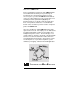
don’t hesitate to call us and benefit from I+ME’s extensive knowledge - your need is our desire. Our merger with the french corporation ACTIA in 1995 allowed us to become a powerful supplier for the European automotive industry. ACTIA products include diagnostic systems for automotive service and maintenance as well as development and production of high-quality on-board electronics.
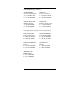
I+ME ACTIA Representatives SI-KWADRAAT Nuenen, Netherlands T: +31 40 2631185 F: +31 40 2838092 ACTIA SA Toulouse, France T: +33 05 61176161 F: +33 05 61554231 NOHAU ELEK. AB Malmö, Sweden T: +46 40 592200 F: +46 40 592229 ACTIA INC. Bedford, Texas USA T: +1 817 5710435 F: +1 817 3559513 If needed, please contact our associates below. ATAL SPOL SRO Tabor, Czech Rep.
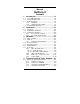
Manual NetPorty II Contents 1 Introduction......................................... 1-1 1.1 1.2 1.3 Your I+ME NetPorty II ......................................1-2 System Requirements ......................................1-4 Delivery Contents .............................................1-5 1.3.1 Standard................................................ 1-5 1.3.2 Supplementary Support ........................ 1-5 1.4 Technical Specifications ...................................1-6 2 Installation.......
5 6 Glossary .............................................. 5-1 Literature ............................................. 6-1 A B C LevelX API LevelX Demos PcCANControl Administration of Document Document version: 1.
Your I+ME NetPorty II. Overview, Systemrequirements, Delivery contents and s.o.
Introduction Your I+ME NetPorty II 1.1 Your I+ME NetPorty II The NetPorty II is an improved portable network adapter. It is designed to connect devices with RS232 or Centronics interface to the CAN bus. With its features it is an ideal general purpose hardware for industrial and automotive analyzes and diagnostics. With NetPorty II you can visualize bus-traffic and configure components within a CAN network. It enables you to transfer software from or to control components.
Introduction Your I+ME NetPorty II I+ME ACTIA is always eager to full fill the needs of our customers. If problems should occur, please refer to Troubleshooting. If the problem persists, then feel free to contact our after-sales support hotline using the following number: After-sales service * I+ME ACTIA GmbH Rebenring 33 D-38106 Braunschweig Germany. Tel: ++ 49 (531) 38 701 38 Fax: ++ 49 (531) 38 701 88 e-mail : info@ime-actia.de Version 1.
Introduction System Requirements 1.2 System Requirements PC requirements: • standard PC with RS232 or Centronics (EPP 1.7 or 1.9) interface • other device with standard RS232 interface (used signals described in chapter Hardware) Version 1.
Introduction Delivery Contents 1.3 1.3.1 Delivery Contents Standard Your NetPorty II delivery package (Order code: IME 1602401) includes: • 1 NetPorty II • 1 System user manual (hardware/software) • Transfer tools to NetPorty II • LevelX software driver for design of 32 bit Windows applications (Windows '95 and Windows NT), including sample programs running on standard firmware • PCCANControl for Windows, Windows '95 and Windows NT version • RS232 adapter cable set 1.3.
Introduction Technical Specifications 1.4 Technical Specifications General Characteristics of NetPorty II Processor Protocol Interface Physical Interface Memory Temperature Range Connector Housing Display Dimensions Power Supply Version 1.03 1-6 80C165, @36,84MHz 1 x SJA1000, @ 16 MHz 1 x 82527, @16MHz 1 x UART CAN: according to ISO 11898 (PCA 82C251) 512 x 16 KByte RAM, 128 x 8 KByte Flash 0° .. .+ 55 °C 9pin sub-min-D CAN according to CiA/DS 102 plastic, protection class IP30 3 DUO-LED 95.
Introduction Technical Specifications Options Memory Physical interface: Diagnosis Channel CAN Cable Power supply Firmware 64 KB EPROM instead of flash ISO Low Speed (ISO 11519) ISO 9141 physical interface CAN optional galvanic disconnect 1 m Cable for adaptation 230 V/AC to regulated 8 V/DC 110 V/AC to regulated 8 V/DC Individual firmware on request Version 1.
Installing your NetPorty II. Step by step installation procedures for hardware and software.
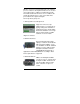
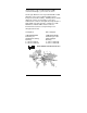
Installation Overview 2.1 Overview This chapter gives detailed information about installing the NetPorty II hardware and about the necessary software drivers which make NetPorty II access possible. The NetPorty II is delivered with access driver and applications for Windows 95 and Windows NT. To get your NetPorty II operational follow the installation guide lines. 2.2 Installing the Hardware To install the hardware you should connect the NetPorty II to the serial or to the parallel port of your PC.
Installation Installing the Hardware It is also necessary to connect the NetPorty II with a power supply. Therefore an external power unit can be used to supply the NetPorty II via the power connector or via the 9 Pin D-Sub CAN-connector. Centronics CAN Power supply Serial RS232 If all connections are done NetPorty II is operational and the next step is the software installation. Version 1.
Installation Installing the Software 2.3 Installing the Software 2.3.1 If you start at serial port Driver installation: 1 Insert the CD. The setup programm will start automatic, if not please start the program “START.EXE” in root path. 2 Go to "Software Installation" 3 Choose your operating system, is important. 4 Choose your hardware component at the selection box then press "Start Installation". If the file is started (*.com file), follow the steps on the screen. If necessay type in the password.
Installation Installing the Software Problems: It is possible you chose an incorrect COM port. Start PcCANControl again and choose an other COM port. 2.3.2 If you start at parallel port 1 Make sure that your PC parallel port uses the EPPmode. You have to control it under BIOS setup. In this version the NetPorty II supported the EPP versions 1.7 and 1.9. If necessary configure your PC and re-start it. 2 Follow steps 1-5 under chapter 2.3.1. 3 Configure the right driver. Change to directory “..
Installation Installing the Software This software is a Win32-Console-Application and runs under Win95 and WinNT. Usage: - Connect your NetPorty II with one serial port. - If you do not use COM1 please change it into the file L.BAT. - Start L.BAT. - If you get error messages like "BSL: no response from the target hardware" it is possible that you have used the wrong COM port. - If you get the message below "-- COMx Loading bootload.h86..
The technical components, there specifications and the way they work together.
Hardware Micro controller 3.1 Micro controller The I+ME NetPorty II includes the 16-bit Siemens 80C165 micro controller on a piggy back. The controller’s clock frequency is 36,84MHz. The following recourses are used: Port 2.14 [EX6IN] Port 2.15 [EX7IN] CS0-CS1 CS2-CS3 CS4 Version 1.
Hardware Memory 3.2 Memory The I+ME NetPorty II is equipped with Flash (CS0) 128 KByte (x 8 bit) SRAM (CS1) 512 KByte (x 16 bit) Optional it can be equipped with Flash 512 KByte (x 8 bit) and RAM 128 Kbyte (x 16 bit) 3.2.1 NetPorty II internal buffers: To avoid lost data (CAN is faster than the communication channels to the PC) the transfer-objects are buffered in the NetPorty II. The biggest buffer is between CAN reception and the communication channel to the PC (448kByte).
Hardware Protocol Interface 3.3 Protocol Interface The product has two CAN protocol chips at a frequency of 16 MHz. The SJA1000 chip is connected to the 9 pin D-SUB connector with the CiA pinning. The optional 82527 is also connected to the 9 pin D-Sub connector without physical line driver. The C165 uses the CS2 signal to select the SJA1000. The NetPorty II can be equipped with a second CAN channel. Therefore a 82527 will be mounted on the PCB. The C165 uses the CS3 signal to select the 82527.
Hardware Physical Interface 3.4 Physical Interface NetPorty II has the transceiver chip 82C251 (according to ISO 11898) as physical interface. It is not galvanic disconnect. The standard physical interface is linked to the SJA1000, the Output Control Register must be set to 0xFA. To connect the second CAN channel or the ISO 9141 channel an optional physical line driver have to be ordered. 3.
Hardware Connector 3.6 Connector 3.6.1 3.6.1.1 9pol sub-min-D male 1 CAN Channel The CAN connector is based on the CiA standard if only one CAN channel is used. It is a 9pol sub-min-D male connector. Figure 3-1 Standard CAN Connector Pins 1, 4 and 8 are not used by NetPorty II Version 1.
Hardware Connector Pin Signal 1 nc 2 CAN_L 3 CAN_GND 4 5 nc CAN_SHIELD 6 7 POWER_GND CAN_H 8 9 nc POWER_V+ Description not connected CAN_L bus line (dominant low) CAN ground (connected on the cable shield) not connected CAN ground (connected on the cable shield) power supply input ground CAN_H bus line (dominant high) not connected power supply input +7..32V The power input and the CAN lines are galvanic disconnect with a limit to ± 50V.
Hardware Connector 3.6.1.2 More than 1 CAN Channel The pinning is different if more than one CAN channel is used. Figure 3-2 Pinning for more than 1 CAN channel Version 1.
Hardware Connector Pin Signal 1 Uni_Out2 2 CAN_L 3 CAN_GND 4 Uni_Out0 5 CAN_SHIELD 6 7 POWER_GND CAN_H 8 Uni_Out1 9 POWER_V+ Description Connected to Port 6.7 CAN_L bus line (dominant low) CAN ground (connected on the cable shield) Connected to Port 6.5 or UART Rx or CAN2 RX0 CAN ground (connected on the cable shield) power supply input ground CAN_H bus line (dominant high) Connected to Port 6.6 or UART Tx or CAN2 TX0 power supply input +7..
Hardware Connector 3.6.2 25pol sub-min-D male To connect the NetPorty II with the PC it is possible to use the Centronics (LPT) port directly or to use the adapter cable to use the RS232 (COM) port. In both cases the pinning of the 25pol sub-min-D male is the same.
Hardware Connector 3.6.3 Cable set for serial connection Cable length: 30cm 25 pin female 23 20 19 16 18 24 21 22 25 9 pin female 1 2 3 4 5 6 7 8 9 Signal CD Rx Tx DTR GND DSR RTS CTS RI Version 1.
Hardware Connector 3.6.4 Power Supply The NetPorty II can be powered by an external power supply Therefore the connector is specified for the power supply jack below: The power connector is a DC3.5/1.3 mm type. That means the internal diameter is 1.3mm. Ø3,5mm min. 9,0mm Figure 3-3 Power Connector for NetPorty II Version 1.
Common problems and how to solve them. How to get in touch with our after-sales support experts if you so desire. 4 Troubleshooting & Techn.
Troubleshooting & Techn. Support What to do if you have problems 4.1 What to do if you have problems First and foremost, please read Installation very closely and make sure that you performed your installation exactly as described. For developers: The Key is often used in developing environments in combination with the API and/or DLL. If the PcCANControl software is functioning properly, then there is no problem with general CAN access. You should check your usage of the API of DLL.
Troubleshooting & Techn. Support What to do if you have problems 4.1.1 Solutions for all parts ... The system crashes after choose the hardware at PcCANControl: The selected memory area is not free, or the selected interrupt is being used by another application. Make sure that no conflicts exist on your system. If you get a blue screen under Win NT it is most likely that a memory or IRQ conflict is occur.
Troubleshooting & Techn. Support What to do if you have problems 4.1.2 Solutions for PCMCIA The system crashes after the installation of the Key client: The selected memory area is not free, or the selected interrupt is being used by another application. Refer to Installation. The system crashes when the Key is inserted or removed: The selected memory area is not free, or the selected interrupt is being used by another application. Refer to Installation.
Troubleshooting & Techn. Support What to do if you have problems The Key is inserted and PcCANControl starts with the message: I+ME CARD not available or drive not ready. Some aspect of the resource allocation is wrong. Refer to Installation for more information. 1.1.1 Non-Supported PCMCIA Drives In the current version there are some PCMCIA drives which are incompatible with the PCMCIA Key. Today, as a general rule, some PCI connected drives result in compatibility problems.
Troubleshooting & Techn. Support What to do if you have problems 4.1.3 Solutions for NetPorty II You start PcCANControl but the connection doesn’t work correct: For parallel port usage it is necessary to have the EPP-loader-firmware (BOOTLOAD.H86) in the NetPorty II -Flash-EPROM. All Porty's are delivered with this loader! You have overwrite the delivered EPP-Loader by your own firmware. In this case it is possible to download the EPPfirmware again into the NetPorty II -Flash.
Troubleshooting & Techn. Support What to do if you have problems The NetPorty II doesn’t work under parallel port: Use the right EPP mode on BIOS. It can be only one of the EPP modes work with one Win-System together. In past we find out that EPP 1.7 is necessary for Win9x and EPP 1.9 is necessary for Win NT. Please try out the right mode.
Troubleshooting & Techn. Support What to do if you have problems If you encounter difficulties which are not discussed in the manual, or if you need more help than is offered in Installation and Troubleshooting, please call our after-sales service. Our experts will do their best to solve whatever problem you might have. Version 1.
For better understanding...
Glossary Glossary Adapter A piece of hardware which contains one or more PCMCIA sockets.The Adapter contains the interface between the Socket Controller and the Host System. AUTOEXEC.BAT A set of commands in the form of a batch file program that are automatically executed by DOS to help configure your system when you Boot-Up your computer. BIOS An abbreviation for Basic Input/Output System. A set of instructions/routines stored in ROM.
Glossary Socket-Controller A PC system hardware component that manages the operation of PCMCIA sockets in conjunction with system software. SYSTEM.INI A Windows initialization file (similar to the CONFIG.SYS file for DOS) that contains Windows device drivers, commands and settings you can use to customize Windows for your system's hardware. Upper-Memory Memory area within the PC address space between 640 KB and 1 MB. This area is used by hardware devices like graphics controller.
For more informations ...
Literature Literature [1] SAB 80C167CR User Manual Siemens AG. [2] SAB C167CR Description of the On-chip CAN-Module Siemens AG. [3] CiA DS 102-1CAN in Automation e.