
Specifications
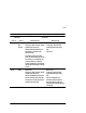

3–6
Controller and Host Addressing
Logically Connecting the Storage Array to the
Host
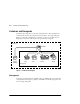
The combination of storage devices is called a storage array. The controller uses a
two-step mapping process to logically connect the host to the storage array:
■ Step1—The controller maps the physical devices on its six device buses to
storage containers that you have created.
■ Step 2—The controller maps its internal containers to user-created logical units
that are directly accessible by the host.
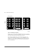
Mapping the Physical Devices with Device PTL
Addressing
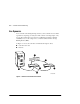
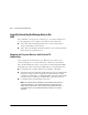
Your controller has six SCSI–2 device ports. Each device port connects to an
enclosure that supports 1 to 4 devices called targets. Every device uses LUN 0.
The controller identifies the location of devices based on a Port-Target-LUN (PTL)
numbering scheme. The controller uses the PTL address to locate physical devices.
■ P—Designates the controller’s SCSI device port number (1 through 6).
■ T—Designates the target identification (ID) number of the device. Valid target ID
numbers for a single-controller configuration and dual-redundant controller
configuration are 0 through 15, excluding ID numbers 4 through 7. ID 6 and ID 7
are reserved for the controller pair, and ID numbers 4 and 5 are never used.
■ L—Designates the logical unit (LUN) of the device.
NOTE: The controller operates with BA370 rack-mountable enclosures that are
assigned ID numbers 0, 2, and 3. These ID numbers are set through the PVA
module. Enclosure ID number 1, which houses devices at targets 4 through 7, is
not supported. Do not use device target ID numbers 4 through 7 in a storage
subsystem.