
Specifications

5–16
Configuring an HSG80 Array Controller
The following steps show how to connect a pair of dual-redundant controllers to the
host using two switches.
Before cabling, note the following:
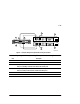
■ Ports
❏ The active ports are port 1, controller A and port 2, controller B.
❏ The standby ports are port 2, controller A and port 1, controller B.
❏ Once logical units are added, the active ports will have access to the units.
❏ For a more detailed explanation of active vs. standby ports and how units are
assigned on each port, see “Assigning Unit Numbers in Transparent Failover
Mode,” page 3–10.
■ Cables connecting into the switch
❏ The cables going from port 1 on both controllers must go into different
switches. Similarly, the cables from port 2 on both controllers must go into
different switches.
❏ To limit confusion on the switch port connections, start with switch port 0
and increment the cables into the next switch port as you make connections.
1. Configure the controller. See “Configuring in Transparent Failover Mode,”
page 5–12.
2. Ensure the host and adapter are also configured. See the host user’s guide for
details.
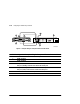
3. Connect the cables between host port 1 on both controllers and the switch ports
on both switches.
Make sure you connect the host port 1 cables into different switches.
4. Connect the cables between host port 2 on both controllers and the switch ports
on both switches.
Make sure you connect the host port 2 cables into different switches.