
Specifications

Replacement Procedures 2–55
3. Shut down the controllers.
■ In single-controller configurations, shut down “this controller” with the following
command:
SHUTDOWN THIS_CONTROLLER
■
In dual-redundant controller configurations, shut down the “other controller” first,
then shut down “this controller” with the following commands:
SHUTDOWN OTHER_CONTROLLER
SHUTDOWN THIS_CONTROLLER
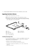
When the controllers shut down, the reset buttons and the first three LEDs are lit
continuously (see Figure 2–4). Receiving this indication can take several minutes,
depending on the amount of data that needs to be flushed from the cache modules.
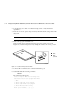
4. Remove the program card ESD cover on “this controller.”
5. Press and hold the reset button while ejecting the program card from “this
controller” by pressing the program card eject button .
6. Press and hold the reset button while inserting the replacement program card.
The “this controller” automatically restarts and is ready to handle I/O once the CLI
becomes responsive.
7. Replace the program card ESD cover on “this controller.”
8. Verify that the master enclosure PVA SCSI ID number reads ID 0. If not, reset it to
ID 0.
9. In a dual-redundant controller configuration, repeat step 4 through step 7 for the “other
controller.”
10. Mount the logical units on the host. If using a Windows NT platform, restart the server.