
Specifications

Replacement Procedures 2–45
Replacing an I/O Module
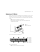
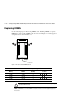
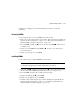
Figure 2–12 shows a rear view of the BA370 enclosure and the relative location of the six
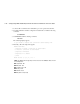
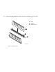
I/O modules (also referred to as ports). Figure 2–13 shows the six I/O modules and the
location of the connectors and securing screws. Use the following steps to replace an I/O
module:
NOTE: This procedure is not applicable for the M1 enclosure.
An I/O module can be replaced in either a single-controller or a dual-redundant controller
configuration using this procedure.
Figure 2–12. I/O module locations in a BA370 enclosure
Figure 2–13. I/O module locations
NOTE: The controller can function with one failed I/O module.
Fans
I/O modules (6 each)
I/O module 1
I/O module 2
I/O module 3
I/O module 4
I/O module 5
I/O module 6
CXO6575B
2
1
4
3
6
5
2
1
CXO5819B
2
3
4
5
6
1