
Specifications
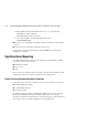

Troubleshooting Resources 4–19
Use the following legend for both tables:
NOTE: If the reset button is flashing and an LED is lit continuously, either the devices on that
LED bus do not match the controller configuration, or an error occurred in one of the devices on
that bus.
Also, a single LED that is lit indicates a failure of the drive on that port.
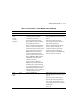
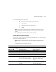
Flashing OCP Pattern Display Reporting
Certain events can cause a flashing display of the OCP LEDs. The event and its resulting
patterns are described in Table 4–4.
NOTE: Reminder: a solid black pattern represents a flashing display. A white pattern indicates
O
FF.
All LEDs flash at the same time and at the same rate.
■
= reset button FLASHING (in Table 4–4) or ON (in TABLE 4–5)
❏
= reset button OFF
●
= LED FLASHING (in Table 4–4) or ON (in TABLE 4–5)
❍
= LED OFF
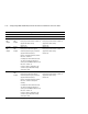
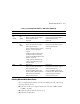
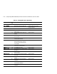
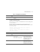
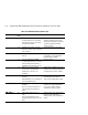
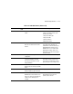
Table 4–4 Flashing OCP Patterns
Pattern OCP
Code
Error Repair Action
■❍❍❍❍❍●
1 Program card EDC error. Replace program card.
■❍❍❍●❍❍
4 Timer zero on the processor is bad. Replace controller.
■❍❍❍●❍●
5 Timer one on the processor is bad. Replace controller.
■❍❍❍●●❍
6 Processor Guarded Memory Unit (GMU) is
bad.
Replace controller.
■❍❍●❍●●
B Nonvolatile Journal Memory (JSRAM)
structure is bad because of a memory
error or an incorrect upgrade procedure.
Verify the correct upgrade (see the
HSG80
Array Controller ACS Version 8.X Release
Notes
). If error continues, replace
controller.
■❍❍●●❍●
D One or more bits in the diagnostic
registers did not match the expected
reset value.
Press the reset button to restart the
controller. If this does not correct the
error, replace the controller.