Operator Manual © 2012 Genmega www.genmega.
Operator Manual TABLE OF CONTENTS 1. INTRODUCTION 1.1 Features 1.1.1 Genmega G2500™ Series ATM 1.2 Specifications Genmega G2500™ Specifications 1.2.1 Dimensions and Component Locations 1.2.2 Front Panel Identification 1.2.3 Cash Dispensing Unit 1.2.4 Receipt Printer 1.2.5 Main Control Board 1.2.6 Operating Environment 1.3 Warranty/Service 2. INSTALLATION 2.1 Genmega G2500™ Installation 2.1.1 Unpacking 2.1.2 Physical Installation 2.1.3 Hardware Setup 3. PROGRAMMING 3.1 Initial Setup 3.1.
Operator Manual 3.5 Transaction Setup 3.5.1 Dispense Limit 3.5.2 Denomination 3.5.3 Fast Cash 3.6 TCP/IP Setup 4. OPERATION 4.1 Opening and Closing 4.1.1 Opening the Security Door 4.1.2 Closing the Security Door 4.1.3 Opening the top Bezel 4.1.4 Closing the top Bezel 4.1.5 Operating and Changing the Combination Lock 4.1.6 Operating and Changing the Electronic Lock 4.2 Cash Operations 4.2.1 Adding Cash to the Cassette (TCDU) 4.2.2 Emptying the Reject Bin (TCDU) 4.2.3 Adding Cash to the Cassette (MCDU) 4.2.
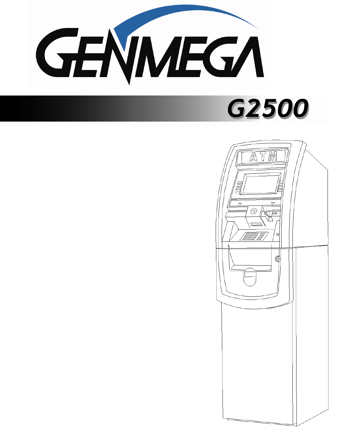
Operator Manual FEATURES 1.1.1 The Genmega G2500™ Introducing the Genmega G2500 series retail ATM. Designed and engineered to meet the needs of the highly competitive retail ATM market, this innovative machine combines all the features you expect, built on a flexible platform allowing you to custom fit each machine to its location and traffic volume.
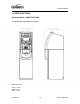
Operator Manual 1.2 SPECIFICATIONS Genmega G2500™ SPECIFICATIONS 1.2.1 Dimensions and Component Location Fig. 1 Dimensions WEIGHT: 206 lbs. Height = 56.22” Width = 15.83” Depth = 22.53” Introduction 1.
Operator Manual Component Location 1. LCD & Customer Keypad 2. Card Reader Slot 3. Receipt Printer Slot 4. Cash Tray 5. Front Panel 6. Front Panel Lock 7. Security Cover 8. Security Cover Lock 9. Security Door 10. Combination Lock Introduction 11. Security Door Handle 12. Cash Dispensing Unit 13. Receipt Printer 14. Main Control Board 15. Ear Phone Jack 16. Power Supply 17. Speaker. 1.
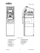
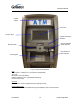
Operator Manual 1.2.2 Front Panel Identification Lighted Topper LCD Panel Function Keys Lighted Transaction Guidance DIP Card Reader (EMV Optional) Receipt Printer Voice Guidance ADA Required EPP Keypad Fig.
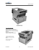
Operator Manual 1.2.3 Cash Dispensing Unit Cash Dispensing Unit (1000 Note - SCDU) CASH DISPENSING UNIT Dispensing Speed: 2.5 notes/second Capacity of 800 new notes (fixed cassette) Capacity of 1000 or 1700 notes (removable) Reject Bin Double note detect module Support for polymer notes (Canada) *Optional dispensers include: 1700 note removable cassette MCDU 3400 note dual-cassette (1700x2) HCDU Introduction 1.
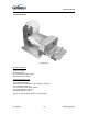
Operator Manual 1.2.4 Receipt Printer Receipt Printer RECEIPT PRINTER Thermal line printer 36 characters/line Semi-automatic roll paper setting Motorized front push rollers PAPER SPECIFICATIONS One sided thermal paper Factory paper is thermal side out (but either way will work) 6 inch outside diameter roll 2 ¼” inch wide (3” wide printer optional) Core inside diameter 11/16 inch 21# weight (paper thickness) Optional 3” Printer supports printing of receipt graphic Introduction 1.
Operator Manual 1.2.5 Main Control Board Samsung S3C2440AL-40 RISC 32-bit CPU 64 MB RAM WinCE™ 5.0 Operating System Modem: 56,000 bps dial-up modem TCP/IP Ethernet connection - Onboard SSL Electronic Journal: 40,000 transactions (upload to USB or SD memory Device) Battery back-up for set-up parameters (NVRAM) Real time clock 1.2.
Operator Manual 1.3 WARRANTY/SERVICE MANUFACTURERS WARRANTY Genmega, Inc. provides a limited one-year parts warranty for the G2500™ series ATM. Genmega guarantees your G2500™ model ATM to be free from defects in materials and workmanship. The one-year parts warranty begins 15 days from the original ATM shipping date.
Operator Manual INSTALLATION 2.1 Genmega G2500™ INSTALLATION 2.1.1 UNPACKING Step 1 Upon receipt of your new Genmega ATM, check the box and packaging for any damage. If you suspect any damage, mark the shipping receipt to indicate suspected concealed damage. Do not discard the ATM packaging materials until you have verified any shipping damage claim. Contact your distributor immediately if you see any shipping damage. It’s also advisable to take photos of any damage.
Operator Manual Step 4 Open the vault door bezel with the key provided. See page 4.1 for Opening and Closing instructions. Step 5 Using the supplied combination (see lock manual for default combination), open the Vault door. The default combination should be changed as soon as possible. Refer to page 4.5 (dial) or 4.7 (electronic) for instructions on opening or changing the lock. 2.1.
Operator Manual Step 4 Remove the cash cassette from its packing box (removable cassette dispensers only). Fill the cassette or cash drawer with the appropriate amount of notes, and carefully place it in the Cash Dispensing Unit. Place the appropriate denomination label on the front of the cassette. See page 4.9 for instruction. Step 5 Before closing the vault, thoroughly test the combination lock by locking and unlocking the lock several times.
Operator Manual PROGRAMMING 3.1 INITIAL SETUP 3.1.1 ACCESSING THE OPERATOR FUNCTION To access the Operator Menu, press these keys in order [ENTER] – [CLEAR] – [CANCEL] – [1] – [2] – [3]. Note: The Operator Function menu can only be accessed when the machine is either in service (“insert your card” screen) or out of service. If the machine is attempting to connect to the host or initializing, you will not be able to use the key commands to access the Operator Function Menu.
Operator Manual Shown the left is the complete Operator Function menu, depending on which password you entered (operators, service, master) you may not see certain functions. For example, if you use an operator password you will not see the Host Setup button, as you will not have access to that menu. Programming 3.
Operator Manual 3.1.2 WHEN AN ERROR OCCURS Step 1 From this screen, press (OP) Operator Menu, to access the Main Menu. Dev. Ini. Will reinitialize the machine and reboot. Step 2 “ENTER PASSWORD” will be displayed. Enter the Master, Service or Operator Password to continue. Contact your distributor for default passwords. Remember to press the ENTER key after typing password! Step 3 NOTE: If the machine goes out of service, the error code will not always appear on the screen.
Operator Manual 3.1.3 Function Keys and EPP Keypad G2500 LCD display Function Key layout This keypad layout and table below will help while learning how to input text and numbers while programming your Genmega ATM. When in a text entry screen, the F1, F3 and F5 keys are used to switch character maps between upper and lower case as well as special characters.
Operator Manual 3.2 HOST SETUP The Host Setup menu provides access to the parameters necessary to connect the ATM to the processor. Master Password is required to access most of these options; however Service password allows basic access for troubleshooting purposes. 3.2.1 KEY MANAGEMENT Access to Key Management requires entering a “Secure Mode” which engages additional security measures (per VISA specification) to prevent Master Key tampering.
Operator Manual Successful entry of both passwords will grant access to the Key Management screen. From the moment the Key Management area is entered, a 5 minute timer begins. At the end of 5 minutes, regardless of what you are doing (entering a master key for example) the Key Management area times out and you will be taken back to the Host Setup menu. Making a mistake during this process can start a 30 second reset timer.
Operator Manual CHANGE PASSWORD This allows you to set each part of the “Secure Mode” Password. As with the other passwords used in the G2500™, each must be a 6 digit number. If you change the password and cannot remember it, you must clear RAM on the pin pad to reset. NOTE: In compliance with PCI specifications, you must change the Secure Mode Passwords from default before any Master Keys can be entered.
Operator Manual 3.2.2 SET TERMINAL ID NUMBER Step 1 From the Host Setup Menu, go to Terminal ID. Terminal ID number is provided by the processor and is individual for your ATM. It identifies your ATM on the network and any transactions done on your machine will be linked to that number. This number is obtained either through your dealer or processing company. 3.2.
Operator Manual Step 3 Once you have selected Host Phone #1 or Host Phone #2 you will be prompted with the following screen. Using the numbers on the keypad press the first number of your phone number. Configuration Scheduled: When this option is set to ‘Scheduled’, upon backing out of the menu and going back in service, the ATM will initiate a configuration request with the host and download a new working key.
Operator Manual 3.2.6 HEALTH CHECK MESSAGE Health Check is an option that will send a system status signal to your processor at a set interval. Check with your dealer or processor to determine if they are prepared to receive this type of messaging. To Enable, simply access the menu from Host Setup. Use the Host Send button to enable or disable the feature and the Message Send Interval button to set how often the machine will broadcast its status (in hours).
Operator Manual 3.2.7 REMOTE MONITOR SYSTEM (RMS) Remote Monitoring is the ability to dial into your ATM and send or retrieve information using Remote Management Software (RMS). RMS EN / DISABLE This will allow the ATM to be monitored remotely. Enable Disable The ATM will answer incoming RMS calls. The ATM will not answer any incoming calls.
Operator Manual RMS SEND PHONE / IP This is the number or IP address the ATM will call if there is an out of service condition. Press the button for either number and enter the number for the computer you want the ATM to call. Using the numbers on the keypad press the first number of your phone number. You can use the <, > keys on the keypad to move back and forth (to correct any mistakes, or edit existing numbers).
Operator Manual To enable the RMS Schedule options, you must first enable RMS Send, and input the phone number or IP address of your RMS PC. Remember that for Internet communications you MUST have a publicly addressable IP address for your RMS computer so the ATMs can contact it. Talk to your internet provider or IT personal about how best to do this. With RMS Send Enabled, you can now set the RMS Schedule Options RMS Schedule: (Enable/Disable) this turns on and off the Schedule system.
Operator Manual 3.2.8 TRIAL DAY TOTAL Trial Day Total feature allows the ATM to complete a Day Total operation (without actually closing out the machine) at a predetermined time each day. This is useful if you are doing accounting of your ATM on a day-to-day basis. Your processor cuts off its transactions each day at a set time. By enabling Trial Day Total at the same time, your day’s balance should match the host.
Operator Manual 3.3 THE SYSTEM SETUP MENU 3.3.1 SET CLOCK The Set Clock menu allows you to set the clock built into the ATM to the appropriate date and time. You should set this for local time in the area the machine is to be installed. Note that with each transaction you will see also see a “Host” time, this is the local time for the processor and may be different from local time at the ATM.
Operator Manual 3.3.2 OPTIONAL LANGUAGES The Genmega G2500™ ATM supports 4 on screen languages: English, French, Spanish and Korean. The optional languages will display on the welcome screen, then the customer will be prompted to choose a language to be used for the rest of that transaction. NOTE: The optional languages are displayed on screen only and do not print on the receipt or journal. Receipts, journals and operator menus are always in English.
Operator Manual 3.3.4 ISO 1, 3 EN/DISABLE The ISO Tracks are the three tracks available for the card swipe head to read. The ATM is already defaulted to read from Track #2 (which is why it’s not shown). This parameter should not be changed. Changing the ISO tracks can cause the ATM to not read cards properly. 3.3.5 CHANGE PASSWORDS The ATM uses three passwords to provide security to the operator menu system. These are Operator, Service and Master.
Operator Manual To change a password, press the button for the appropriate password. You will be prompted to enter the new password and then enter it a second time to verify. If you forget your password please contact your dealer or distributor for service. NOTE: All passwords MUST be 6 digits. If you use a password that is less than 6 digits, the passwords may default back to factory if the machine is power cycled. If your customer wants a 4 or 5 digit password, add zeros to the end to make it 6 digits.
Operator Manual 3.3.6 DEVICE SETUP The Device Setup menu provides options to adjust parameters of the various peripherals. Under normal circumstances you should not need to make changes to these parameters. The default settings are optimized for your particular machine. Genmega recommends only using these tools under the direction of an Authorized Service Provider (ASP) or Genmega Technical Support. 3.3.6.1 SPR SETUP The SPR Setup allows you to set the maximum column width for the receipt printer.
Operator Manual 3.3.6.2 MODEM SETUP The Genmega G2500™ series use an onboard 56K modem. The modem is preset at the factory for optimal use. Changing these settings can cause your machine to not communicate or may slow communication speeds. Do not make changes to the modem settings. MODEM SPEED This sets the speed at which the modem will begin communication with the host. The default speed is 2400.
Operator Manual 3.3.6.5 CDU SETUP The CDU (Cash Dispensing Unit) or Dispenser contains programming relative to its application and country of destination. This programming does not need to be altered, however in the event that the dispenser looses its factory programming the CDU Setup application can correct any problems. NOTE: Incorrect programming of the dispenser will cause the machine to go out of service.
Operator Manual 3.3.7 SET REBOOT TIME The G2500™ contains a feature which automatically reboots the machine at a 24 hour interval. By default this will occur at 03:00 am. This adjustable in 1 hour increments. 3.3.8 SERIAL NUMBER The serial number is a unique number programmed into your machine at Genmega. It not only identifies your machine for warranty purposes, but also for remote monitoring using RMS. The first 4 digits refer to the model type, and the last 6 is production cycle.
Operator Manual 3.4 CUSTOMER SETUP MENU The Customer Setup menu controls surcharge information, BIN lists, receipt options, advertisements and keypad lighting. 3.4.1 CHANGE MESSAGE The Messaging options for the ATM are a welcome message and a receipt header message. The Welcome message allows line of 35 characters, which will appear at the top of the main screen (above the center graphic). The receipt header is up to 4 lines of 25 characters, which will appear at the top of each receipt. Programming 3.
Operator Manual WELCOME MESSAGE Once you have selected Welcome Message from the Change Message Menu, you will be prompted with the following screen. RECEIPT HEADER Once you have selected Receipt Header from the Change Message Menu, you will be prompted with the following screen. See the above instructions for navigating this menu. Programming 3.
Operator Manual 3.4.2 BIN LISTS BIN numbers are card numbers that you have preset with your processor to not be surcharged. You must set this up with your processor, who will then give you numbers to enter in the list. These numbers will reference cards that you wish to not be charged a surcharge for transactions. The ATM will hold up to 60 numbers. If you need more BIN numbers, there is a file that can be created to load several thousand more numbers. Contact technical support for instructions.
Operator Manual 3.4.3 OPTIONAL FEATURES The G2500™ ATM offers several optional functions to improve performance and keep the ATM functional in the event of a paper problem (jam, out of paper etc.) LOCATION NAME Adding a name to this location will print the name entered onto the journal records and print all setup. This is purely a convenience option and is not required. SELECT RECEIPT This feature allows the ATM to complete transactions even though it may not be able to dispense a receipt.
Operator Manual 3.4.4 CHANGE PROCESSOR Host Processor selection changes the communications protocol to specifically match your particular processor. In most cases this is set at the factory when your machine is ordered, however in the event that the machine needs to be reprogrammed for a new processor, it may be necessary to change the processor mode. To access the Host Processor mode, enter the Customer Setup menu using the Master Password.
Operator Manual 3.4.5 SURCHARGE MODE The Surcharge menu displays the current rate at which customers are charged per transaction, the person or account that the surcharge funds are sent to and whether or not the option to surcharge is enabled or disabled. The information programmed here must match the information given to the processor at the time the account was created.
Operator Manual PERCENT This allows you to set the surcharge amount as a percentage of the overall amount the customer is withdrawing per transaction. Check with your processor to make sure that they support this function. SURCHARGE OWNER The surcharge owner can be up to 25 characters long. This owner name will appear at the bottom of each transaction receipt.
Operator Manual 3.4.6 GRAPHICS The Genmega G2500™ is capable of displaying up to 8 customized graphic screens. These graphic files are created on a computer and then downloaded into the ATM either directly at the ATM using a SDRAM card or by using the Genmega Remote Management Software (RMS). When the advertisements are loaded and enabled they will rotate in order while the ATM is waiting for a transaction and also while the transaction is processing.
Operator Manual From the Customer Setup Menu, select the Coupon Setting, Logo Option. Note that only ATMs with 3” printers support coupon logos. The G1900 model does not support this feature, only text based coupons. Select Enable to activate the coupon function. Choose Edit Coupon to enter the text for each optional coupon. Choose Line 1 to edit the top line and Line 2 to enter the bottom line for each coupon. If you leave the lines blank, then that coupon will not print in the rotation Programming 3.
Operator Manual 3.5 TRANSACTION SETUP 3.5.1 DISPENSE LIMIT The dispense limit is the maximum amount of money a customer can withdraw in a single transaction. The ATM will dispense a maximum of 40 notes per transaction. So the dispense limit can be a maximum of 40 times the denomination of notes your using.
Operator Manual 3.5.2 DENOMINATION The Denomination is the type of bill that each cassette will be dispensing. The ATM offers a second cassette as an option. This second cassette can be programmed to dispense notes, it can also dispense a preset number of bill sized coupons with each transaction and finally it can dispense a “value coupon”, where you would set the value of the coupon and the customer could purchase this using their card.
Operator Manual 3.5.3 FAST CASH Fast Cash amounts are presented to the customer if they choose a Withdrawal transaction. These amounts appear on screen as an easy method of selecting how much cash they wish to withdraw for that transaction. The amounts must be multipliers of the denomination amount. For Example: If your dispensing $10 bills then you can use $10, $20, $30, $40, $50 etc. If your dispensing $20 bills then you can use $20, $40, $60, $80, $100 etc.
Operator Manual 3.6 TCP/IP SETUP TCP/IP Setup is done in several menus. First you need to specify TCPIP from the Communications Menu: [See page 3.27] Check with your processor for which protocol settings they are expecting. To change, go to: Operator Function Menu Æ Customer Setup Æ Change Processor Æ Communication Change this value to SSL PassThrough (or other depending on processor) Once you change from Modem, to one of the TCP/IP settings, several other menus change to support various network functions.
Operator Manual The ATM IP information is set using the menu found at: Operator Function Menu Æ System Setup Æ Device Setup Æ ATM TCP Setup This menu is only active if you have the communication mode set to TCP [See page 3.24] These settings will be dependant on the network connection available at the location where the ATM is deployed. It may be necessary to contact the ISP or Network provider for the location to determine how this should be set.
Operator Manual TCPIP Troubleshooting When trying to connect your ATM to the internet, there are two error codes which can occur. 2511 – This means that the ATM sent a request, however nothing responded. Typically this means the ATM cannot get out on the internet. To test this, we suggest replacing the Host IP number with one from a common public website like Google [74.125.224.50] or Yahoo [98.137.149.56] Those ‘public’ IP addresses will allow pinging.
Operator Manual OPERATION 4.1 OPENING AND CLOSING 4.1.1 Opening the Security Door Step 1 Turn the vault bezel key clockwise to open the lower vault bezel. The key will remain in the lock after you turn it. Step 2 To unlock the Dial or optional Electronic Lock (see the manufacturers lock manual included in the open me first box for default combination) and then refer to Section 4.1.6 for lock instructions Step 3 Turn the security Door Handle counter-clockwise; then pull the security door to open.
Operator Manual 4.1.2 Closing the Security Door Step 1 With the security door handle turned counterclockwise, close the security door and turn the security door handle clockwise until it is locked. The electronic lock mechanism will lock itself once the Thandle has returned to its vertical position. The dial combination lock must be turned counter-clockwise to lock. Step 2 Check the T-handle to make sure the lock has locked itself.
Operator Manual 4.1.3 Opening the top Bezel Step 1 The upper bezel lock on the Genmega G2500™ is located on the back side of the top of the machine. Insert the Bezel key and turn it clockwise to open. (Optional Topper Shown) Step 2 With the Front Panel key turned, pull the Front Panel outward. Operation 4.
Operator Manual 4.1.4 Closing the top Bezel Step 1 Push the Front Panel slowly until it is against the lock mechanism. Note: you must unlock the top bezel lock before the bezel will close all the way. Step 2 To lock the top bezel, turn the Bezel key counterclockwise until the key can be removed. (Optional Topper Shown) Operation 4.
Operator Manual 4.1.5 Operating and Changing the Combination Lock (non-electronic) Before operating the lock or changing the combination, READ THE INSTRUCTIONS THOROUGHLY. Changing Index Opening Index At the top of the dial ring, an index is provided for normal dialing and opening. At the side of the opening index (11 o'clock), a changing index is provided for use only when setting a new combination.
Operator Manual Changing to a New Combination To make up a new combination, select 3 sets of numbers of your own choosing. • DO NOT USE NUMBERS BETWEEN 0 AND 20 FOR YOUR LAST NUMBER • DO NOT USE NUMBERS ENDING IN 0 OR 5 • DO NOT USE NUMBERS IN A RISING OR FALLING SEQUENCE (e.g. 35-50-75) Insert Figures (3) Step 1 Using the changing index, dial the existing combination as explained in paragraphs 1-3 above.
Operator Manual 4.1.6 Operating and Changing the Electronic Lock Before operating the lock or changing the combination, READ THE INSTRUCTIONS THOROUGHLY*. *See manufacturers lock manual included in the “Open Me First Box” The LA GARD “LG Basic” series electronic lock uses a touch key pad for all lock functions. Power is supplied to the lock via a standard 9-volt Alkaline battery which contained within the external portion of the lock. The lock will warn of low voltage by repeatedly beeping.
Operator Manual Changing to a New Combination NOTE: Combination is required to be 6 digits. Combinations of less than 6 digits will not work. Step 1 Begin by entering six zeros. ( 000000 ) Step 2 Enter the existing combination one time Step 3 Enter the new combination twice. As each six digit sequence is entered, a beep is heard. Step 4 If the procedure is not performed correctly, at the end a triple-beep is heard and the lock will revert back to the previous combination.
Operator Manual 4.2 CASH OPERATIONS 4.2.1 Adding Cash to the Cassette (TCDU) Step 1 Open the Security Door. (Please see 4.1.1 OPENING/CLOSING THE SECUIRTY DOOR.) Step 2 For Genmega G2500™ with a fixed cassette dispenser (TCDU) use the following steps. For machines equipped with the removable cassette dispenser (SCDU or MCDU) please continue to Section 4.2.3. With the security door open, remove the slide tray screw and slide the dispenser all the way out.
Operator Manual Step 4 Push the slide the push plate located inside the cash tray back (towards the rear of the dispenser) until it latches in place. Step 5 Press on the latch bar to release the push plate against the notes. TIPS ABOUT ADDING BILLS: 1. 2. 3. 4. Fan the notes so that the notes are not sticking together. Remove all the notes with holes or notes that are torn. Unfold the folded notes. Place all the notes correctly. Operation 4.
Operator Manual 4.2.2 Emptying the Reject Bin Step 1 Insert the key into the reject bin lock and turn to unlock. Step 2 Pry back on the plastic tabs at the base of the arrow stickers on each side of the reject bin. Lift the reject bin lid. Step 3 With the reject bin open, remove any notes and then close the top. Turn the key to lock the reject bin in place. Operation 4.
Operator Manual 4.2.3 Adding Cash to the Cassette (SCDU or MCDU) Step 1 Open the Security Door. (Please see 4.1.1 OPENING/CLOSING THE SECUIRTY DOOR.) Step 2 With the security door open, remove the cassette. Lift up on the handle while supporting the bottom of the cassette while removing. Step 3 To avoid damage, never use force while removing or installing the cassette. If anything beyond gentle force is required while handling the cassette, contact your service personal. Operation 4.
Operator Manual Step 4 Open the cassette using the key shown in Section 2 (page 2.2) Step 5 Pull back on the cash plate and load the bills against the rollers at the back of the cassette. If you pull the cash plate back all the way it will lock at the front of the cassette. Push the green lever on the cash tray to release. TIPS ABOUT ADDING BILLS: 5. 6. 7. 8. Fan the notes so that the notes are not sticking together. Remove all the notes with holes or notes that are torn. Unfold the folded notes.
Operator Manual 4.2.4 Emptying the Reject Bin Step 1 To open the reject bin, pull back on the tabs located on the sides of the reject bin door. Step 2 Remove any notes found in the reject bin and close the door by pressing it shut. Remember to include the number of bills found in the reject bin when settling the cassette. Operation 4.
Operator Manual 4.2.5 Loading the Receipt Paper Step 1 Open the top Bezel. (See 4.1.4 Opening the top Bezel.) Step 2 Place the paper onto the supplied spindle with the Coated Side Out as shown in the picture. Feed the paper out through the back, where it will curl back under the tension bar. Step 3 Prepare the new paper roll. Note below. NOTE: 1. Make sure the roll is in its proper roll form. (A deformed roll may cause jamming problems.) 2.
Operator Manual Step 4 Feed the paper over the bar behind the roll and under the spring loaded tension bar. Slide the paper through the guides. The paper will not feed until the machine is initialized (powered on). If the paper does not feed, make sure the paper is all the way in the loading guide. Also make sure the roller assembly is closed (see below) Step 5 The roller assembly can be opened by pressing down on the green lever in front of the printer.
Operator Manual 4.3 SETTLEMENT MENU Choose Settlement from the Operator Function menu. This menu controls how many bills have been added to the ATM as well as generating Day total and Cassette total reports. ADDING CASH Step 1 Press the Add Cassette button. Step 2 Using the main keypad, enter the number of bills added to the cassette (not the amount of money). Step 3 Press the enter key when finished to set the amount.
Operator Manual DAY TOTAL The Day Total function keeps a running total of the ATMs transaction activity. When you press day total, the ATM will print a report showing transaction totals starting from the last time a day total was done until now. At the same time, the G2500 will dial into the Host Processor and retrieve their totals for the same time period. To the left is an example of a Day Total Report. Once the report is printed, the ATM will reset these values to 0 and begin recording from this point.
Operator Manual CASSETTE TOTAL The Cassette Total function prints a report detailing the number of bills that have been loaded into the cassette and how many bills were dispensed, either to the customer, the reject bin or used during a dispenser test. This report will show totals from the last time you ran a Cassette Total to the current date. After the Cassette Total has been printed, all the values will reset to zero.
Operator Manual 4.4 JOURNAL MENU The Journal is an electronic record of all transactions, errors and some programming changes made to the ATM. Depending on the size of each entry, the memory can hold up to 40000 records. Each entry into the journal is indexed with a 5-digit sequence number starting with <00000>. Once the journal memory has reached it’s maximum limit, it will begin to overwrite the oldest entries.
Operator Manual LAST X PRINT The Last X Print option allows you to bypass the marker set when printing a journal and go back to recover an older record (so long as the record still exists in memory). For example, you print a journal and it includes sequence numbers <00001> to <00100>. If you wanted to go back and reprint journal number <00080> you would need to do a Last X Print for 20 records (100-20=80) this would give you records 100-80.
Operator Manual 4.5 REPORTS MENU The reports menu provides statistical information as well as troubleshooting and error information. ERROR CODE If the machine is out of service, and you are unfamiliar with the error code being displayed (or none is displayed), this screen will provide error descriptions as well as corrective action for the currently displayed code. Press the Error Code button to enter this screen.
Operator Manual ERROR SUMMARY This report is a running total of all errors that have occurred to your ATM. It lists the errors by the number of times they occurred. Sometimes your machine can go out of service and no error code is displayed (usually with communications problems). If this happens, check the error summary, as the code will be displayed here. You can print these errors To the left is a sample of an error summary report. Press Clear to clear the report and start over.
Operator Manual DIAGNOSTICS 5.1 DIAGNOSTICS MENU The ATM features built-in diagnostics features to assist you in troubleshooting any problems that may develop. Below is the main diagnostics menu. CASH DISPENSER This will test the ability of the cash dispenser to pull a note from one or both cassettes (based on how the CDU is programmed) and send it to the reject bin. You can choose from the first cassette, second cassette or both cassettes at once.
Operator Manual KEYPAD This tests the keypads of the ATM. Press the Key Matrix button and a map of all keys will display on the screen. Press the different keys on each keypad (main and LCD) and the appropriate key will blink on the screen. Pressing the key on the main keypad will stop this test and return to the diagnostics menu. CARD READER This will test the three tracks of the card scanner to ensure they are reading properly.
Operator Manual CUSTOMER TRANSACTIONS 6.1 OPENING PROCEDURES This section explains how to place your ATM in service. Step 1 Open the front panel and turn the power on. (see page 4.3) Step 2 If there is no receipt paper, load the receipt paper. (see page 4.15) Step 3 Open the security door and replenish the cash cassette. (see page 4.1) Step 4 Go into the OPERATOR FUNCTION mode and input the number of bills in the cash cassette. (See page 4.17) Step 5 Exit the OPERATOR FUNCTION MODE.
Operator Manual 6.2 WITHDRAWAL TRANSACTION Step 1 Insert the card. Step 2 Enter the pin number and press the “ENTER” key. Step 3 Press the “WITHDRAWAL” screen key. Step 4 If a “SURCHARGE” option is enabled, the “SURCHARGE” screen will be displayed. Select “YES” to continue, or “NO” to cancel. Customer Transactions 6.
Operator Manual Step 5 If “YES” is selected, the following screen will be displayed. Select the desired option. Step 6 Select the desired amount to be withdrawn. If the desired amount is not displayed, select the “OTHER” screen key. Step 7 After the desired amount is entered, the ATM dials the processor and requests approval for the transaction. When authorization is received from the processor, the cash will be dispensed. Step 8 After dispensing cash, a receipt will be printed.
Operator Manual 6.3 BALANCE INQUIRY TRANSACTION Step 1 Insert the card. Step 2 Enter the pin number and press the “ENTER” key. Step 3 Press the “BALANCE” screen key. Step 4 The following screen will be displayed. Select the desired option. Customer Transactions 6.
Operator Manual Step 5 The ATM dials the processor and requests approval for the transaction. Step 6 When authorization is received from the processor, the following screen will be displayed and the receipt will be printed. Customer Transactions 6.
Operator Manual 6.4 TRANSFER TRANSACTION Step 1 Insert the card. Step 2 Enter the pin number and press the “ENTER” key. Step 3 Press the “TRANSFER” screen key. Step 4 The following screen will be displayed. Select the desired account to be transferred “FROM.” Customer Transactions 6.
Operator Manual Step 5 Select the target account to be transferred “TO.” Step 6 Enter the desired amount to be transferred and press the “ENTER” key. Step 7 The ATM dials the processor and requests approval for the transaction. Step 8 When the authorization is received from the processor, the following screen will be displayed and the receipt will be printed. Customer Transactions 6.
Operator Manual 6.5 CLOSING PROCEDURE This section explains the closing procedure for the ATM. Step 1 Perform the “DAY TOTAL” and “CASSETTE TOTAL” functions in the “OPERATOR FUNCTION MODE.” Step 2 Open the security door. Remove the cash from the Cash Cassette and Cash Reject bin. Step 3 Print the Journal. Step 4 If the result of the DAY TOTAL and CASSETTE TOTAL does not match the amount counted in the Cash Cassette, refer to the Journal for verification.
Operator Manual 6.6 ERROR RECOVERY If an error occurs the following screen will be displayed. Step 1 To access the Operator Function menu, press the following keys in order , then , then then 1, then 2, then 3. Step 2 Verify the Error that has occurred through the “ERROR CODE” of the “REPORT MENU” in the “OPERATOR FUNCTION,” menu and perform the corrective action, then press the “DEVICE INITIALIZE” screen key.
Operator Manual APPENDIX A: Error Codes ERROR CODES 20001 ERROR DESCRIPTION CORRECTIVE ACTION Unable to load a cassette. Remove and replace cassette – Check the micro-switch located on the inside left wall of the dispenser. Replenish the cash – If using less than 75 bills, disable the “Low Cash Warning” in the Transaction Setup Menu. Empty the Reject Bin – If the bin is empty, do a Day Total and then a Cassette Total – If that doesn’t help, check AP, BIOS and CDU ROM versions.
Operator Manual ERROR CODES C0028 C0030 C0031 C0032 C0033 C0036 C0037 C0039 C003A C0041 C0042 C0043 C0044 C0045 C0046 C0047 ERROR DESCRIPTION CORRECTIVE ACTION Count sensors not cleared Main Motor encoder is not synchronized Forward motor encoder not synchronized.
Operator Manual ERROR CODES C005A C005B C0060 C0062 C006A C0070 C0072 C007A C007C C007D C0080 C0081 C0082 C0083 C0084 C0085 C0086 C0090 C0091 C0092 C0093 C0094 C0095 C0096 C0097 C009A ERROR DESCRIPTION Undefined 2nd cassette fails to pick up notes 3rd cassette inlet sensor not cleared 3rd cassette inlet sensor not cleared Note jam at 2nd cassette exit 4th cassette inlet sensor not cleared 4th cassette inlet sensor not cleared Note jam at 4th cassette exit 4th cassette fails to pick up notes 4th cassette no
Operator Manual ERROR CODES D0024 D0039 D0051 D0052 D0053 D0054 D0055 D0057 D0058 D0061 D0075 D0078 D0080 D0083 D0086 D0091 D0092 D0093 D0094 D0095 D0096 D0097 D0098 D0099 D009A D009B D009C D009D D009E D009F D00A0 D00A1 D00A2 D00A3 D00A4 ERROR DESCRIPTION CORRECTIVE ACTION Exceeds issuer withdrawal limit. No credit account. Insufficient funds. No checking account. No savings account. Expired Card. Invalid PIN. Transaction not permitted – card Transaction not permitted – Terminal Exceed withdrawal limit.
Operator Manual ERROR CODES D00A5 ERROR DESCRIPTION CORRECTIVE ACTION Verify that version of ATM Software matches host processor. Contact host processor. D1800 FS omitted (after total cash dispense amount in day close). FS omitted (after total non cash dispense amount in day close). FS omitted (after surcharge amount in day close message). FS omitted (after surcharge in configuration message). ETX omitted (from configuration message). Modem is not responding. No Connection. ENQ not received from host.
Operator Manual ERROR CODES F000A F000B F000C F000D F000E F000F F0010 F0011 F0013/ 14 F0015 F0016 ERROR DESCRIPTION CORRECTIVE ACTION Master Key is empty. Host Telephone Number is not set. Error Retry timer is not set. RMS Password is not set when RMS is enabled. RMS phone number is not set when RMS send is enabled. Terminal ID is not set. Routing ID is not set.
Operator Manual APPENDIX B: CLEARING NVRAM To clear NVRAM on the Genmega G2500™, begin by entering the Operator Function Menu using the Master Password. Next enter the Customer Setup Menu. Press the lowest button on the right side of the LCD panel. This will give you access to the CLEAR NVRAM Menu. *** WARNING *** Once in the CLEAR NVRAM Menu, there is no extra authorization before data will be wiped out permanently.
Operator Manual APPENDIX C: Master Key Installation Master Key Installation Master keys are entered only through an approved EPP (Encrypting Pin Pad) device and are stored in the keypad. These keys, along with another key downloaded from your processor are used to encrypt the ‘PIN’ numbers for customer transactions. Two Passwords (Secure Mode Passwords) are required in order to enter ‘Key Mode’ and change any options.
Operator Manual 1) Select Key Mode The table below describes the format for each key mode. DES 2 - 16 digit master keys entered as Part A and Part B. Dual Master Key 2 - 16 digit master keys entered as Part A and Part B (a common key is entered, and then a working key is downloaded from the host). Unique Key, DES 2 - 16 digit master keys entered as Part A and Part B - with 10 digit unique serial number entered prior to each part.
Operator Manual 2) Entering A Master Key Master Key security requires that no one person has access to all parts of the key. To ensure this, the processor will provide keys in separate sealed envelopes (sometimes referred to as “key components”). Each envelope contains either one or two 16 digit keys and in the case of unique key, a serial number. The diagram below shows a sample Unique Key, TDES master key.
Operator Manual Once you have selected Part A or B, you’ll be prompted to enter a Key Index. This index points to the location where the key will be stored. There are 16 possible memory locations (0-15) available. Unique master keys must be stored at location #12, and MAC keys at location #15. The interface will default the values for Unique and MAC keys regardless of what you enter. It is very important to remember that both parts of a key must be entered on the same index.
Operator Manual The 16 digit alpha-numeric key is entered using the pin-pad only. Letters are entered by using the arrow and function keys. Use the pin-pad layout below. 1 2 3 D 4 5 6 E 7 8 9 F A 0 B C EPP (Encrypted Pin Pad) Master Key Alpha-Numeric Key Layout Master Key Installation C.
Operator Manual At this point the left (or first 16 digit) portion of the master key has been entered successfully. If you are entering a 32 bit key (TDES), the second or “Right” half of the key is entered next. This option will only appear when in TDES mode. After entering the right portion of the key successfully you’ll be prompted with a check digit as shown below. Verify the check digit with the information provided by the processor.
Operator Manual After successfully entering both the left and right portions of Part A, you’ll be returned to the Edit Master Key menu. At this point you can proceed with Part B, or if Part B is to be entered at a later time you can exit the menu and power off the machine until both halves of the key are entered. Part B is entered with the same procedure given for Part A. Enter the left and right (for TDES) portions of the keys and verify the check digits against what has been provided by the processor.
Operator Manual APPENDIX D: Custom Screen / Coupon Graphics Advertisement screens can be loaded to the Genmega G2500™ machine either using a SDRAM card (at the ATM) or by using remote monitoring software (to load remotely). Please see below for basic file format specifications and instructions for use with a SDRAM card. WELCOME Center Advertisement Graphic Width : 422 Pixels Height : 309 Pixels File Name center1.bmp center2.bmp ….. center8.
Operator Manual Loading Graphics using SD (Secure Digital) card SD card should be less than 2GB capacity and formatted as FAT or FAT16 file system SD card reader is required to load files from your PC To prepare the SD card for uploading graphics. 1. Remove all the data from the SD card. 2. Create a blank file called update.acu and save it on the card. To create this file: a. Open up a blank notepad document. [Start Æ All Programs Æ Accessories Æ Notepad] b. Save the blank document as “update.
Operator Manual 3. Open the SD card in ‘My Computer’, and create a folder called “Common”. 4. Open the “Common” folder, and create a sub-folder called “img4SCR”. 5. Inside the img4SCR folder is where you want to copy all your graphic files. - The graphic files must follow the naming convention that we describe on page 1. (ie: center1.bmp, center2.bmp). 6. Once your graphic files are copied, insert the SD card into the SD card slot on the mainboard located behind the LCD. 7.
Operator Manual How to install Coupon Graphic If ordered with the optional 3” wide receipt printer, the G2500 is capable of printing a low resolution graphic on each receipt. To use this feature, you’ll need to create the graphic (BMP file format) to the specifications listed below, and then add the file to the machine using the SD RAM card slot located on the rear of the main circuit board. Once the graphic is loaded, it will copy into memory each time the machine is powered on.