
Specifications


5–28 Maintenance and Service Guide
Removal and Replacement Procedures
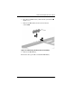
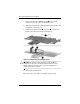
3. Remove the two silver PM1x6 screws
1
that secure the
charger board to the system board (Figure 5-18).
4. Turn the system board top side up with the stereo speaker and
headphone jacks facing you.
5. Lift up on the left front side
2
and center
3
of the charger
board to disconnect it from the system board.
Figure 5-18. Removing the Charger Board
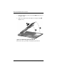
Ä
CAUTION: Do not lift the charger board by the right side 4. The
material on the right side of the board is thinner and more prone to
damage. Failure to follow this caution can result in damage to the
charger board and the computer.
6. Remove the charger board.
Reverse the above procedure to install the charger board.