
Specifications


5–20 Maintenance and Service Guide
Removal and Replacement Procedures
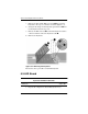
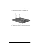
5. Remove the following screws:
❏
two pewter TM2 × 8 screws
1
that secure the top cover
to the base enclosure (Figure 5-13)
❏
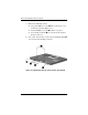
two black TM2 × 4 screws
2
from the rear panel
❏
two 5.0 mm screwlocks
3
on each side of the external
monitor connector
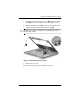
6. Use a 9/64” hex wrench to remove the two bushing guides
4
on each side of the docking connector.
Figure 5-13. Removing the Top Cover Screws (Continued)