b Maintenance and Service Guide Compaq Evo N200 Series Document Part Number: 233117-001 September 2001 This guide is a troubleshooting reference used for maintaining and servicing the notebook. It provides comprehensive information on identifying computer features, components, and spare parts, troubleshooting computer problems, and performing computer disassembly procedures.
© 2001 Compaq Computer Corporation Compaq and the Compaq logo Registered in U. S. Patent and Trademark Office. Evo is a trademark of Compaq Information Technologies Group, L.P. Microsoft and Windows are trademarks of Microsoft Corporation. Intel and Pentium are trademarks of Intel Corporation. All other product names mentioned herein may be trademarks of their respective companies. Compaq shall not be liable for technical or editorial errors or omissions contained herein.
Contents 1 Product Description 1.1 Features . . . . . . . . . . . . . . . . . . . . . . . . . . . . . . . . . . . 1–2 1.2 Clearing a Password. . . . . . . . . . . . . . . . . . . . . . . . . . 1–4 1.3 Power Management . . . . . . . . . . . . . . . . . . . . . . . . . . 1–5 1.4 Computer External Components . . . . . . . . . . . . . . . . 1–6 1.4 Design Overview . . . . . . . . . . . . . . . . . . . . . . . . . . . 1–16 2 Troubleshooting Using the PhoenixBIOS Setup Utility . . . . . . . . . . . . . . .
2.17 Nonfunctioning Device . . . . . . . . . . . . . . . . . . 2.18 Nonfunctioning Keyboard . . . . . . . . . . . . . . . . 2.19 Nonfunctioning Pointing Device . . . . . . . . . . . 2.20 Network or Modem Connection Problems . . . 2–19 2–20 2–21 2–22 3 Illustrated Parts Catalog 3.1 Serial Number Location . . . . . . . . . . . . . . . . . . . . . . . 3.2 Computer System Major Components . . . . . . . . . . . . 3.3 Miscellaneous Plastics Kit Components . . . . . . . . . . 3.4 Cable Kit Components . . . . . .
.12 RTC Battery . . . . . . . . . . . . . . . . . . . . . . . . . . . . . . 5.13 System Board . . . . . . . . . . . . . . . . . . . . . . . . . . . . . 5.14 Charger Board . . . . . . . . . . . . . . . . . . . . . . . . . . . . 5.15 Modem/NIC Cable . . . . . . . . . . . . . . . . . . . . . . . . . 5.16 Audio Cable . . . . . . . . . . . . . . . . . . . . . . . . . . . . . . 5–22 5–24 5–27 5–29 5–31 6 Specifications A Connector Pin Assignments B Power Cord Set Requirements 3-Conductor Power Cord Set . . . .
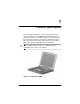
1 Product Description The Compaq Evo N200 Series of Personal Computers offers advanced modularity, a 700-MHz Intel Pentium III processor with 64-bit architecture, industry-leading Accelerated Graphics Port (AGP) implementation, and extensive multimedia support. The computer provides desktop functionality and connectivity through the optional Mobile Expansion Unit (MEU). Evo N200 computer models have an SKU number of ✎ All 243420-B21 and a config. code of KCJZ. Figure 1-1.
Product Description 1.1 Features The computer has the following features: 1–2 ■ Intel Pentium III 700-MHz processor, with 256-KB integrated cache ■ ATI Mobility M1, 8-MB SDRAM ■ 192 MB standard memory (64 MB integrated on system board, 128 MB in memory expansion compartment) ■ Microsoft Windows 2000 ■ 10.4-inch, XGA, TFT (1024 × 768) display, with over 16.8 million colors ■ TouchPad pointing device ■ Mini PCI V.
Product Description ■ External AC adapter with power cord ■ Support for a 6-cell Lithium ion (Li ion) primary battery pack in the battery bay and an optional external 4-cell Li ion ■ 20-GB high-capacity hard drive ■ Speaker ■ Connectors for: ❏ RJ-45 network ❏ RJ-11 modem ❏ External monitor ❏ Mobile Expansion Unit (MEU) ❏ Stereo speaker/headphone ❏ Microphone ❏ Universal serial bus (USB) ❏ AC power Maintenance and Service Guide 1–3
Product Description 1.2 Clearing a Password If the notebook you are servicing has an unknown password, follow these steps to clear the password. These steps also clear CMOS: 1. Prepare the computer for disassembly. Refer to Section 5.3, “Preparing the Computer for Disassembly,” for more information. 2. Remove the RTC battery (refer to Section 5.12, “RTC Battery”). 3. Wait approximately five minutes. 4. Replace the RTC battery and reassemble the computer. 5. Connect AC power to the computer.
Product Description 1.3 Power Management The computer comes with a collection of power management features that extends battery operating time and conserves power.
Product Description 1.4 Computer External Components The external components on the display and right side of the computer are shown in Figure 1-2 and described in Table 1-1. . Figure 1-2.
Product Description Table 1-1 Front and Right Side Components Item Component Function 1 Stereo speaker/ headphone jack Connects stereo speakers, headphones, headset, or television audio. 2 Microphone jack Connects a single sound channel microphone. 3 Display release latch Releases the display to open the computer. 4 Hard drive Supports the removable primary hard drive.
Product Description The computer rear panel and left side components are shown in Figure 1-3 and described in Table 1-2. Figure 1-3.
Product Description Table 1-2 Rear Panel and Left Side Components Item Component Function 1 RJ-45 jack (network models only) Connects the network cable. RJ-11 jack (internal modem models only) Connects the modem cable to an internal modem. 2 ✎ ✎ A network cable is included with network models A modem cable is included with internal modem models. 3 External monitor connector Connects an external monitor or overhead projector.
Product Description The keyboard components are shown in Figure 1-4 and described in Table 1-3. Figure 1-4.
Product Description Table 1-3 Keyboard Components Item Component Function 1 F1 through F12 function keys Perform preset functions. 2 Caps lock key Turns on the caps lock function. 3 Fn key Used with hotkeys to perform preset hotkey functions. 4 Windows logo key Displays Windows Start menu. 5 Windows application key Displays a menu when using a Microsoft application. The menu is the same one that is displayed by pressing the right mouse button.
Product Description The external components on the top of the computer are shown in Figure 1-5 and described in Table 1-4. Figure 1-5. Top Components Table 1-4 Top Components Item Component Function 1 Power switch Turns on the computer. To turn off the computer, use the operating system Shut Down command. 2 Easy Access buttons (4) Provide quick access to the Internet. 3 Num lock light On: Num lock is on and the embedded numeric keypad is enabled.
Product Description Table 1-4 Top Components (Continued) Item Component Function 4 Caps lock light On: Caps lock is on. 5 Scroll lock light On: Scroll lock is on. 6 Battery light On: A battery pack is charging. Blinking: A battery pack that is the only available power source has reached a low-battery condition. 7 Hard drive light On: The primary hard drive is being accessed. 8 Power light On: Power is turned on. Blinking: Computer is in Standby.
Product Description The external components on the bottom of the computer are shown in Figure 1-6 and described in Table 1-5. fm Figure 1-6.
Product Description Table 1-5 Bottom Components Item Component Function 1 External battery release latches (2) Release the external battery pack. 2 Mini PCI compartment cover Contains the mini PCI modem or network interface card. 3 Vents Provides airflow to cool internal components. 4 Primary battery release latch Releases the primary battery pack from the battery bay. 5 Battery bay Holds the primary battery pack.
Product Description 1.4 Design Overview This section presents a design overview of key parts and features of the computer. Refer to Chapter 3, “Illustrated Parts Catalog,” to identify replacement parts, and Chapter 5, “Removal and Replacement Procedures,” for disassembly steps.
2 Troubleshooting Å WARNING: Only authorized technicians trained by Compaq should repair this equipment. All troubleshooting and repair procedures are detailed to allow only subassembly/module level repair. Because of the complexity of the individual boards and subassemblies, no one should attempt to make repairs at the component level or to make modifications to any printed wiring board. Improper repairs can create a safety hazard.
Troubleshooting Troubleshooting Flowcharts Table 2-1 Troubleshooting Flowcharts Overview Section Description 2.1 Initial troubleshooting 2.2 No power, part 1 2.3 No power, part 2 2.4 No power, part 3 2.5 No power, part 4 2.6 No video, part 1 2.7 No video, part 2 2.8 Nonfunctioning docking station 2.9 No operating system (OS) loading 2.10 No OS loading from hard drive, part 1 2.11 No OS loading from hard drive, part 2 2.12 No OS loading from hard drive, part 3 2.
Troubleshooting Initial Troubleshooting Begin Troubleshooting N Go to Section 2.2, No Power. Is there power? Y N Check LED board, speaker connections. Beeps, LEDs, or error Messages? N Y Go to Section 2.17, Nonfunctioning Device. All drives working? N Y Go to Section 2.6, No Video. Is there video? (no boot) N Keyboard/ pointing device working? Y N Y Go to Section 2.9, No OS Loading. Is the OS loading? N Connecting to network or modem? Y N Is there sound? Y Go to Section 2.15, No Audio.
Troubleshooting 2.2 No Power, Part 1 No Power (Power LED is off) Remove from docking station if applicable. N N Power up on battery power? Go to Section 2.3, No Power, Part 2. Power up on battery power? *Reset power. Y Y N N Power up on AC power? Power up on AC power? *Reset power. Y Go to Section 2.4, No Power, Part 3. Y Y Power up in docking station? Done N 1. Reseat power cables in docking station and at the AC outlet. 2. Ensure the AC power source is active. 3.
Troubleshooting 2.3 No Power, Part 2 Continued from Section 2.2, No Power, Part 1. Visually check for debris in battery socket and clean if necessary. Y Power on? Done N Check battery by recharging, moving it to another computer, or replacing it. N Replace power supply (if applicable). Power on? Y N Done Power on? Go to Section 2.4, No Power, Part 3.
Troubleshooting 2.4 No Power, Part 3 Continued from Section 2.3, No Power, Part 2. Plug directly into AC outlet. Y Power LED on? Done N Reseat AC adapter in computer and at power source. Y Power on? Done N N Power outlet active? External Try different outlet. Y Internal Go to Section 2.5, No Power, Part 4. Replace power cord. Replace external AC adapter.
Troubleshooting 2.5 No Power, Part 4 Continued from Section 2.4, No Power, Part 3. Open computer. Y Reseat loose components and boards and replace damaged items. Loose or damaged parts? N Close computer and retest. N Power on? Replace the following items, if applicable. Check computer operation after each replacement: 1. Internal DC-DC converter* 2. Internal AC adapter 3. Processor board* 4. System board* Y Done *Replace these items as a set to prevent shorting out among components.
Troubleshooting 2.6 No Video, Part 1 No Video Docking Station Go to Section 2.7, No Video, Part 2. Stand-alone or Docking Station? *Note: To change from internal to external display, use the hotkey combination. Standalone Internal or external display*? Y Adjust brightness. Depress lid switch to ensure operation. A Adjust brightness. Y Video OK? Done N Internal External Video OK? Y Video OK? Done Done N N Replace the following one at a time. Test after each replacement: 1.
Troubleshooting 2.7 No Video, Part 2 Continued from Section 2.6, No Video, Part 1. Remove notebook from docking station, if connected. Adjust display brightness. Check brightness of external monitor. N Y Go to “A” in Section 2.6, No Video, Part 1. Video OK? Y Video OK? Done N Check for notebook properly seated in docking station, bent pins on cable, and for monitor connection. Try another external monitor.
Troubleshooting 2.8 Nonfunctioning Docking Station (if applicable) Nonfunctioning docking station Reseat power cord in docking station and power outlet. Check voltage setting on docking station. Reinstall notebook into docking station. Y Reset monitor cable connector at docking station. Docking station operating? Done N Y Docking station operating? N Remove notebook, reseat all internal parts, and replace any damaged items in docking station.
Troubleshooting 2.9 No Operating System (OS) Loading No OS loading Reseat power cord in docking station and power outlet. No OS loading from hard drive, go to Section 2.10. No OS loading form diskette drive, go to Section 2.13. No OS loading from CD- or DVD-ROM drive, go to Section 2.14. No OS loading from network, go to Section 2.20. *Note: Before beginning, always check cable connections, cable ends, and drives for bent or damaged pins.
Troubleshooting 2.10 No OS Loading from Hard Drive, Part 1 OS not loading from hard drive. Y Go to Section 2.11, No OS Loading from Hard Drive, Part 2. Nonsystem disk message? N Reseat external hard drive. Y OS loading? Done N N Boot from CD? N Y Go to Section 2.13, No OS Loading from Diskette Drive. Boot from diskette? Check the setup utility for correct booting order. Y N Change boot priority through the setup utility and reboot.
Troubleshooting 2.11 No OS Loading from Hard Drive, Part 2 Continued from Section 2.10, No OS Loading from Hard Drive, Part 1. Reseat hard drive. N 1. Replace hard drive. 2. Replace system board. CD or diskette in drive? Y Hard drive accessible? Y Done N Remove diskette and reboot. Run FDISK. Y Boot from hard drive? N Done N Create partition, then format hard drive to bootable C:\ prompt. Hard drive partitioned? Y N N Go to Section 2.13, No OS Loading from Diskette Drive.
Troubleshooting 2.12 No OS Loading from Hard Drive, Part 3 Continued from Section 2.11, No OS Loading from Hard Drive, Part 2. N System files on hard drive? Install OS and reboot. Y Y Y Virus on hard drive? OS loading from hard drive? Clean virus. N Done N Y Run SCANDISK and check for bad sectors. Diagnostics on diskette? Replace hard drive. N N Can bad sectors be fixed? Run diagnostics and follow recommendations. Replace hard drive. Y N Fix bad sectors.
Troubleshooting 2.13 No OS Loading from Diskette Drive Y OS not loading from diskette drive. Reseat diskette drive. OS loading? Done N N Y Bootable diskette in drive? Nonsystem disk message? N Install bootable diskette and reboot computer. Y N Go to Section 2.17, Nonfunctioning Device. Boot from another device? Check diskette for system files. Try different diskette. Y N Diskette drive enabled in the setup utility? Y Enable drive and cold boot computer. Y 1. Replace diskette drive. 2.
Troubleshooting 2.14 No OS Loading from CD- or DVD-ROM Drive Y No OS loading from CD- or DVD-ROM drive. N Bootable disk in drive? Disk in drive? N Y Install bootable disk and reboot computer. Try another bootable disk. Install bootable disk. Y Boots from CD or DVD? Done N Y Reseat drive. Boots from CD or DVD? Done N N Booting from another device? Y Y Booting order correct? N Go to Section 2.17, Nonfunctioning Device. Clear CMOS. Refer to Section 1.
Troubleshooting 2.15 No Audio, Part 1 Y Turn up audio internally or externally. No audio Audio? Done N N Y Notebook in docking station (if applicable)? N Go to Section 2.16, No Audio, Part 2. Internal audio? Undock Y Replace the following docking station components one at a time as applicable. Check after each change: Go to Section 2.16, No Audio, Part 2. 1. Reseat docking station audio cable. 2. Replace audio cable. 3. Replace speaker. 4. Replace docking station audio board. 5.
Troubleshooting 2.16 No Audio, Part 2 Continued from Section 2.15, No Audio, Part 1 N Audio driver in OS configured? Reload audio drivers. Y N Correct drivers for application? Load drivers and set configuration in OS. Y Connect to external speaker. N Audio? Y Replace audio board and speaker connections in notebook, if applicable. Y Audio? Done N 1. Replace internal speakers. 2. Replace audio board, if applicable. 3. Replace system board.
Troubleshooting 2.17 Nonfunctioning Device Nonfunctioning device Reseat device. Unplug the nonfunctioning device from the notebook, inspect cables and plugs for bent or broken pins or other damage. Y Any physical device? Fix or replace broken item. Possible bad hard drive. Replace drive. Go to Section 2.9, No OS Loading. Clear CMOS. N Reattach device. Close notebook, plug in power, and reboot. N Device boots properly? Y Done Maintenance and Service Guide Possible bad NIC. Replace card.
Troubleshooting 2.18 Nonfunctioning Keyboard Keyboard not operating properly. Connect notebook to good external keyboard. N External device works? Replace system board. Y Reseat internal keyboard connector (if applicable). N Replace internal keyboard or cable. OK? Y Y OK? Done Done N Replace system board.
Troubleshooting 2.19 Nonfunctioning Pointing Device Pointing device not operating properly. Connect notebook to good external pointing device. N External device works? Replace system board. Y Reseat internal pointing device connector (if applicable). N OK? Replace internal pointing device or cable. Y Y OK? Done Done N Replace system board.
Troubleshooting 2.20 Network or Modem Connection Problems No network or modem connection. N Network or modem jack active? Replace jack or have jack activated. Y Y Connect to non-digital line. Digital line? N N NIC/modem configured in OS? Y Y Reload drivers and reconfigure. OK? Done N Disconnect all power from the notebook and open. Replace NIC/modem if applicable. Y Reseat NIC/modem if applicable. OK? Done N Replace system board.
3 Illustrated Parts Catalog This chapter provides an illustrated parts breakdown and a reference for spare part numbers and option part numbers. 3.1 Serial Number Location When ordering parts or requesting information, provide the computer serial number and model number located on the bottom of the computer as indicated in Figure 3-1. Figure 3-1.
Illustrated Parts Catalog 3.2 Computer System Major Components Figure 3-2.
Illustrated Parts Catalog Table 3-1 Computer System Major Components Item Description Spare Part Number 1 10.
Illustrated Parts Catalog Computer System Major Components (continued) 3–4 Maintenance and Service Guide
Illustrated Parts Catalog Table 3-1 Computer System Major Components (Continued) Item Description Spare Part Number 6 Top Cover (includes TouchPad) 251643-001 7 System board with 700-MHz Intel Pentium III processor and 64 MB SDRAM 128-MB memory expansion board (shipped on system board; not illustrated) 251642-001 8 RTC battery 252443-001 9 Combination modem/network interface card (NIC) 233558-001 10 Charger board 251640-001 11 Base enclosure (includes speaker and left and right external
Illustrated Parts Catalog 3.3 Miscellaneous Plastics Kit Components Figure 3-3.
Illustrated Parts Catalog 3.4 Cable Kit Components Figure 3-4.
Illustrated Parts Catalog 3.5 Miscellaneous Spare Parts Table 3-4 Miscellaneous Spare Parts (not illustrated) Spare Part Number Description Power cord, black, 6 feet Australian Danish European/Middle Eastern/African Italian Japanese 246959-011 246959-081 246959-021 246959-061 197233-001 Korean People’s Republic of China Swiss U.K. English U.S.
Illustrated Parts Catalog Table 3-4 Miscellaneous Spare Parts (not illustrated) (Continued) Description Spare Part Number Logo Kit 251637-001 Mobile Expansion Unit 248871-001 The following options are for use only with the Mobile Expansion Unit: 155532-001 173949-001 102266-001 315082-002 153992-001 Hard drive adapter 8X DVD-ROM drive 4X DVD-ROM drive 24X CD-ROM drive CD-RW drive Modems PC Card modem 233564-001 Modem adapters 234963-221 316920-331 236432-041 257942-001 Hungarian Norwegian Swiss
4 Removal and Replacement Preliminaries This chapter provides essential information for proper and safe removal and replacement service. 4.1 Tools Required You will need the following tools to complete the removal and replacement procedures: ■ Magnetic screwdriver ■ Torx T8 screwdriver ■ Phillips P0 screwdriver ■ 5.
Removal and Replacement Preliminaries 4.2 Service Considerations The following sections include some of the considerations that you should keep in mind during disassembly and assembly procedures. you remove each subassembly from the computer, place the ✎ As subassembly (and all accompanying screws) away from the work area to prevent damage. Plastic Parts Using excessive force during disassembly and reassembly can damage plastic parts. Use care when handling the plastic parts.
Removal and Replacement Preliminaries 4.3 Preventing Damage to Removable Drives Removable drives are fragile components that must be handled with care. To prevent damage to the computer, damage to a removable drive, or loss of information, observe the following precautions: ■ Before removing or inserting a hard drive, shut down the computer. If you are unsure whether the computer is off or in Hibernation, turn the computer on, then shut it down.
Removal and Replacement Preliminaries 4.4 Preventing Electrostatic Damage Many electronic components are sensitive to electrostatic discharge (ESD). Circuitry design and structure determine the degree of sensitivity. Networks built into many integrated circuits provide some protection, but in many cases the discharge contains enough power to alter device parameters or melt silicon junctions.
Removal and Replacement Preliminaries ■ Place reusable electrostatic-sensitive parts from assemblies in protective packaging or nonconductive foam. ■ Use transporters and conveyers made of antistatic belts and roller bushings. Ensure that mechanized equipment used for moving materials is wired to ground and that proper materials are selected to avoid static charging. When grounding is not possible, use an ionizer to dissipate electric charges. 4.
Removal and Replacement Preliminaries 4.7 Grounding Equipment and Methods Grounding equipment must include either a wrist strap or a foot strap at a grounded workstation. ■ When seated, wear a wrist strap connected to a grounded system. Wrist straps are flexible straps with a minimum of one megaohm ±10% resistance in the ground cords. To provide proper ground, wear a strap snugly against the skin at all times. On grounded mats with banana-plug connectors, connect a wrist strap with alligator clips.
Removal and Replacement Preliminaries ■ Nonconductive plastic bags, tubes, or boxes ■ Metal tote boxes ■ Electrostatic voltage levels and protective materials Table 4-1 shows how humidity affects the electrostatic voltage levels generated by different activities.
5 Removal and Replacement Procedures This chapter provides removal and replacement procedures. There are 31 different Torx T8 and Phillips screws, screwlocks, and bushing guides, in 10 different sizes, that must be removed when servicing the computer. Make special note of the size and location of each screw during removal and replacement. Refer to Appendix C, “Screw Listing,” for detailed information on screw sizes, locations, and usage.
Removal and Replacement Procedures 5.1 Serial Number Report the computer serial number to Compaq when requesting information or ordering spare parts. The serial number is located on the bottom of the computer as indicated in Figure 5-1. Figure 5-1.
Removal and Replacement Procedures 5.2 Disassembly Sequence Chart Use the chart below to determine the section number to be referenced when removing computer components. Table 5-1 Disassembly Sequence Chart Section Description # of Screws Removed 5.3 Preparing the computer for disassembly 0 5.4 Computer feet 0 5.5 Modem/NIC 2 5.6 LED cover 0 5.7 Microphone 0 5.8 Keyboard 3 5.9 LED board and cable 2 5.10 Display 4 5.11 Top cover 14 5.12 RTC battery 0 5.
Removal and Replacement Procedures 5.3 Preparing the Computer for Disassembly Perform the following steps before disassembling the computer. Consult the computer Hardware Guide for instructions on the following steps: 1. Shut down the computer. 2. Undock the computer from the MEU, if applicable. 3. Disconnect the AC adapter and external devices. 4. Remove any battery packs inserted into or attached to the computer.
Removal and Replacement Procedures 5.4 Computer Feet The computer feet are adhesive-backed rubber pads. The computer feet are included in the Miscellaneous Plastics Kit (spare part number 251638-001). Refer to Figure 5-2 for the locations of the computer feet. Figure 5-2.
Removal and Replacement Procedures 5.5 Modem/NIC Modem/NIC Spare Part Number Information Combination modem/network interface card (NIC) 233558-001 1. Prepare the computer for disassembly (Section 5.3). 2. Turn the computer bottom side up with the front facing you.
Removal and Replacement Procedures 3. Remove the two black PM2 × 4 screws 1 that secure the mini PCI compartment cover to the base enclosure (Figure 5-3). mini PCI compartment cover is included in the ✎ The Miscellaneous Plastics Kit (spare part number 251638-001). 4. Lift up the left edge of the mini PCI compartment cover and swing it up and to the right 2. 5. Remove the mini PCI compartment cover. Figure 5-3.
Removal and Replacement Procedures 6. Disconnect the modem/NIC cable from the modem/NIC board 1 (Figure 5-4). 7. Slide the modem/NIC cable into the mini PCI compartment until it clears the modem/NIC board 2. 8. Spread the retaining tabs to release the modem/NIC 3. The board tilts up to a 45-degree angle. 9. Remove the modem/NIC by pulling it away from the connector at a 45-degree angle. Figure 5-4. Removing the Modem/Network Interface Card Reverse the above procedure to install the modem/NIC.
Removal and Replacement Procedures 5.6 LED Cover LED cover is included in the Miscellaneous Plastics Kit ✎ The (spare part number 251638-001). 1. Prepare the computer for disassembly (Section 5.3). 2. Turn the computer top side up with the front facing you. 3. Open the computer as far as it will open. 4. Swing the back edge of the LED cover up and forward 1 and remove it 2 (Figure 5-5). Figure 5-5. Removing the LED Cover Reverse the above procedure to install the LED cover.
Removal and Replacement Procedures 5.7 Microphone microphone is included in the Cable Kit (spare part number ✎ The 251639-001). 1. Prepare the computer for disassembly (Section 5.3). 2. Remove the LED cover (Section 5.6). 3. Disconnect the microphone cable 1 from the system board (Figure 5-6). 4. Remove the microphone 2 from the top cover. Figure 5-6. Removing the Microphone Reverse the above procedure to install the microphone.
Removal and Replacement Procedures 5.8 Keyboard Keyboard Board Spare Part Number Information Keyboards Belgian Brazilian Czech Danish French French Canadian German Hebrew Hungarian International Italian Japanese Korean 246339-181 246339-201 246339-221 246339-081 246339-051 246339-121 246339-041 246339-BB1 246339-211 246339-002 246339-061 246339-291 246339-AD1 Latin American Spanish Norwegian Portuguese Russian Spanish Swedish Swiss Taiwanese Turkish U.K. English U.S.
Removal and Replacement Procedures 3. Remove the three black TM2 × 4 screws 1 that secure the keyboard to the top cover and base enclosure (Figure 5-7). 4. Swing the back edge of the keyboard up and forward 2 and rest the keyboard on the top cover. 5. Release the ZIF connector 3 to which the keyboard cable is connected and disconnect the keyboard cable 4. 6. Remove the keyboard. Figure 5-7. Removing the Keyboard Reverse the above procedure to install the keyboard. 5.
Removal and Replacement Procedures 2. 3. 4. 5. Remove the LED cover (Section 5.6). Remove the microphone (Section 5.7). Remove the keyboard (Section 5.8). Release the ZIF connector 1 to which the LED board cable is connected and disconnect the LED board cable 2 (Figure 5-8). 6. Remove the two black TM2 × 4 screws 3 that secure the LED board to the top cover. 7. Remove the LED board 4. Figure 5-8.
Removal and Replacement Procedures LED board cable is included in the Cable Kit (spare part ✎ The number 251639-001). To remove the LED board cable from the system board: 1. Release the ZIF connector 1 to which the LED board cable is connected and disconnect the LED board cable 2 (Figure 5-9). 2. Remove the LED board cable 3. Figure 5-9. Removing the LED Board Cable Reverse the above procedure to install the LED board and LED board cable.
Removal and Replacement Procedures 5.10 Display the display screws are removed, the assembly is ✎ When unsupported. Make sure to provide support for the display when removing the display screws. Display Spare Part Number Information 10.4-inch XGA TFT display 251633-001 1. Prepare the computer for disassembly (Section 5.3) and remove the following components: a. LED cover (Section 5.6) b. Microphone (Section 5.7) c. Keyboard (Section 5.8) d. LED board and cable (Section 5.
Removal and Replacement Procedures 2. Slide the left and right hinge covers away from the computer 1 (Figure 5-10). hinge covers are included in the Miscellaneous Plastics Kit ✎ The (spare part number 251638-001). 3. Disconnect the display inverter 2 and video cables 3 from the system board. 4. Remove the two silver TM2 × 15 screws 4 and the two black TM2 × 5 screws 5 that secure the display to the top cover and base enclosure. Figure 5-10. Removing the Display 5. Remove the display.
Removal and Replacement Procedures ensure proper alignment of the display during replacement, ✎ Toloosely install the screws in the 1, 2, 3, 4 sequence indicated in Figure 5-11. Tighten the screws after all four have been been loosely installed. Figure 5-11.
Removal and Replacement Procedures 5.11 Top Cover Top Cover Spare Part Number Information Top cover 251643-001 1. Prepare the computer for disassembly (Section 5.3) and remove the following components: a. LED cover (Section 5.6) b. Microphone (Section 5.7) c. Keyboard (Section 5.8) d. LED board and cable (Section 5.9) e. Display (Section 5.10) 2. Turn the computer bottom side up with the front facing you.
Removal and Replacement Procedures 3. Remove the six pewter TM2 × 8 screws (Figure 5-12). Figure 5-12. Removing the Top Cover Screws 4. Turn the computer top side up with the rear panel facing you.
Removal and Replacement Procedures 5. Remove the following screws: ❏ two pewter TM2 × 8 screws 1 that secure the top cover to the base enclosure (Figure 5-13) ❏ two black TM2 × 4 screws 2 from the rear panel ❏ two 5.0 mm screwlocks 3 on each side of the external monitor connector 6. Use a 9/64” hex wrench to remove the two bushing guides 4 on each side of the docking connector. Figure 5-13.
Removal and Replacement Procedures 7. Lift up the back edge of the top cover 1 until the TouchPad cable 2 prevents it from lifting any farther (Figure 5-14). 8. Release the ZIF connector 3 to which the TouchPad cable is connected and disconnect the TouchPad cable 4. LED board cable is included in the Cable Kit (spare part ✎ The number 251639-001). Figure 5-14. Removing the Top Cover 9. Remove the top cover. Reverse the above procedure to install the top cover.
Removal and Replacement Procedures 5.12 RTC Battery RTC Battery Spare Part Number Information RTC battery 252443-001 1. Prepare the computer for disassembly (Section 5.3) and remove the following components: a. LED cover (Section 5.6) b. Microphone (Section 5.7) c. Keyboard (Section 5.8) d. LED board and cable (Section 5.9) e. Display (Section 5.10) f. 5–22 Top cover (Section 5.
Removal and Replacement Procedures 2. Disconnect the RTC battery cable from the system board 1 (Figure 5-15). 3. Remove the RTC battery from the slot in the base enclosure 2. Figure 5-15. Removing the Real Time Clock Battery 4. Remove the RTC Battery. Reverse the above procedure to install the RTC Battery.
Removal and Replacement Procedures 5.13 System Board System Board Spare Part Number Information System board with 700-MHz Intel Pentium III processor and 64 MB SDRAM 251642-001 1. Prepare the computer for disassembly (Section 5.3) and remove the following components: a. LED cover (Section 5.6) b. Microphone (Section 5.7) c. Keyboard (Section 5.8) d. LED board and cable (Section 5.9) e. Display (Section 5.10) f. Top cover (Section 5.11) g. RTC battery (Section 5.
Removal and Replacement Procedures 2. Disconnect the left 1 and right 2 external battery terminal cables and the speaker cable 3 (Figure 5-16). Figure 5-16.
Removal and Replacement Procedures 3. Lift up the right side of the system board 1 until it rests at a 45-degree angle. 4. Slide the system board to the right at a 45-degree angle 2 (Figure 5-17). Figure 5-17. Removing the System Board Reverse the above procedure to install the system board.
Removal and Replacement Procedures 5.14 Charger Board Charger Board Spare Part Number Information Charger board 251640-001 1. Prepare the computer for disassembly (Section 5.3) and remove the following components: a. LED cover (Section 5.6) b. Microphone (Section 5.7) c. Keyboard (Section 5.8) d. LED board and cable (Section 5.9) e. Display (Section 5.10) f. Top cover (Section 5.11) g. RTC battery (Section 5.12) h. System board (Section 5.13) 2.
Removal and Replacement Procedures 3. Remove the two silver PM1x6 screws 1 that secure the charger board to the system board (Figure 5-18). 4. Turn the system board top side up with the stereo speaker and headphone jacks facing you. 5. Lift up on the left front side 2 and center 3 of the charger board to disconnect it from the system board. Figure 5-18. Removing the Charger Board Ä CAUTION: Do not lift the charger board by the right side 4.
Removal and Replacement Procedures 5.15 Modem/NIC Cable modem/NIC cable is included in the Cable Kit (spare part ✎ The number 251639-001). 1. Prepare the computer for disassembly (Section 5.3) and remove the following components: a. LED cover (Section 5.6) b. Microphone (Section 5.7) c. Keyboard (Section 5.8) d. LED board and cable (Section 5.9) e. Display (Section 5.10) f. Top cover (Section 5.11) g. RTC battery (Section 5.12) h. System board (Section 5.13) 2.
Removal and Replacement Procedures 3. Disconnect the modem/NIC cable from the system board 1 (Figure 5-19). 4. Remove the modem/NIC cable 2. installing the modem/NIC cable, route the cable between ✎ When the docking connector 3 and the mini PCI connector 4. Figure 5-19. Removing the Modem/NIC Cable Reverse the above procedure to install the modem/NIC cable.
Removal and Replacement Procedures 5.16 Audio Cable audio cable is included in the Cable Kit (spare part number ✎ The 251639-001). 1. Prepare the computer for disassembly (Section 5.3) and remove the following components: a. LED cover (Section 5.6) b. Microphone (Section 5.7) c. Keyboard (Section 5.8) d. LED board and cable (Section 5.9) e. Display (Section 5.10) f. Top cover (Section 5.11) g. RTC battery (Section 5.12) h. System board (Section 5.13) 2.
Removal and Replacement Procedures 3. Disconnect both connectors on the audio cable 1 from the system board (Figure 5-20). 4. Remove the audio cable 2. Figure 5-20. Removing the Audio Cable Reverse the above procedure to install the audio cable.
6 Specifications This chapter provides physical and performance specifications. Table 6-1 Computer Dimensions Height Width Depth Weight .89 in 10.5 in 9.5 in 22 mm 266 mm 242 mm 3.5 lb 1.59 kg Standalone (battery) power requirements Nominal operating voltage (Li ion) Maximum operating power Peak operating power 14.
Specifications Table 6-1 Computer (Continued) Relative humidity Operating Nonoperating 10 to 90% relative humidity, non-condensing 5 to 90% relative humidity, 101.6°F/38.7°C maximum wet bulb temperature Altitude (unpressurized) Operating (14.7 to 10.1 psia) Nonoperating (14.7 to14.4 psia) 0 to 10,000 ft 0 to 3,048 m 0 to 30,000 ft 0 to 9,144 m Shock Operating Nonoperating 10 G, 11 ms, half sine 60 G, 11 ms, half sine Vibration Operating Nonoperating 0.5 G, 10 to 500 Hz, 0.5 oct/min sweep rate 1.
Specifications Table 6-2 10.4-inch XGA, TFT Display Dimensions Height Width Diagonal 6.4 in 8.2 in 10.1 in 162 mm 209 mm 264 mm Number of colors Up to 16.8 million Contrast ratio 125:1 Brightness 130 nits typical on AC power, 70 nits typical on battery power, 115 nits minimum Pixel resolution Pitch Format Configuration 0.264 × 0.
Specifications Table 6-3 Hard Drives 20.0 GB 10.0 GB User capacity per drive1 20.0 GB 10.0 GB Drive height (with drive frame) 0.38 in, 9.5 mm 0.38 in, 9.5 mm Drive width (with drive frame) 2.50 in, 70 mm 2.50 in, 70 mm Interface type ATA-5 ATA-4 2.5 ms 12.0 ms 23.0 ms 2.5 ms 12.0 ms 23.
Specifications Table 6-3 Hard Drives (Continued) 20.0 GB 10.0 GB Physical configuration Cylinders3 Heads Sectors per track3 Bytes per sector 22,784 4 293–560 512 22,784 2 293–560 512 Buffer size3 2 MB 512KB Disk rotational speed 4200 rpm 4200 rpm 66.6 109–203 66.6 109–203 Transfer rate Interface max (MB/s)2 Media (Mb/s)3 1 1 GB = 1,000,000,000 bytes. System capability may differ. 3 Actual drive specifications may differ slightly. Certain restrictions and exclusions apply.
Specifications Table 6-4 Battery Packs Dimensions Primary Lithium ion (Li ion) Height Width Depth Weight Cells External Li ion Height Width Depth Weight Cells External Li ion High Capacity Height Width Depth Weight Cells .78 in 9.06 in 1.84 in .49 lb 4 20 mm 231 mm 47 mm .22 kg .9 in 10.47 in .9 in .48 lb 4 23 mm 266 mm 23 mm .22 kg 1.8 in 10.6 in 1.2 in .93 lb 4 46 mm 269 mm 30 mm .
Specifications Table 6-5 AC Adapter Weight 0.39 lb .18 kg Power supply (input) 90 to 260 VAC RMS Nominal 1.
Specifications Table 6-7 System Interrupts Hardware IRQ System Function IRQ0 System timer IRQ1 Keyboard controller IRQ2 Cascaded IRQ3 COM2 IRQ4 COM1 IRQ5 Audio (default)* IRQ6 Diskette drive IRQ7 Parallel port IRQ8 Real time clock (RTC) IRQ9 Infrared IRQ10 System use IRQ11 System use IRQ12 Internal point stick or external mouse IRQ13 Coprocessor (not available to any peripheral) IRQ14 IDE interface (hard drive and optical drive) IRQ15 System use ✎ PC Cards may assert IRQ3
Specifications Table 6-8 System I/O Addresses I/O Address (hex) System Function (shipping configuration) 000 - 00F DMA controller no. 1 010 - 01F Unused 020 - 021 Interrupt controller no.
Specifications Table 6-8 System I/O Addresses (Continued) I/O Address (hex) System Function (shipping configuration) 0A2 - 0BF Unused 0C0 - 0DF DMA controller no.
Specifications Table 6-8 System I/O Addresses (Continued) I/O Address (hex) System Function (shipping configuration) 2F0 - 2F7 Unused 2F8 - 2FF Infrared port 300 - 31F Unused 320 - 36F Unused 370 - 377 Secondary diskette drive controller 378 - 37F Parallel port (LPT1/default) 380 - 387 Unused 388 - 38B FM synthesizer - OPL3 38C - 3AF Unused 3B0 - 3BB VGA 3BC - 3BF Reserved (parallel port/no EPP support) 3C0 - 3DF VGA 3E0 - 3E1 PC Card controller in CPU 3E2 - 3E3 Unused 3E8 - 3
Specifications vt Table 6-9 System Memory Map Size Memory Address System Function 640 KB 00000000 - 0009FFFF Base memory 128 KB 000A0000 - 000BFFFF Video memory 48 KB 000C0000 - 000CBFFF Video BIOS 160 KB 000C8000 - 000E7FFF Unused 64 KB 000E8000 - 000FFFFF System BIOS 15 MB 00100000 - 00FFFFFF Extended memory 58 MB 01000000 - 047FFFFF Super extended memory 58 MB 04800000 - 07FFFFFF Unused 2 MB 08000000 - 080FFFFF Video memory (direct access) 4 GB 08200000 - FFFEFFFF Unused
A Connector Pin Assignments Table A-1 Stereo Speaker/Headphone Pin Signal Pin Signal 1 Audio out 2 Ground Maintenance and Service Guide A–1
Connector Pin Assignments Table A-2 Microphone Pin Signal Pin Signal 1 Audio in 2 Ground Table A-3 Universal Serial Bus Pin Signal Pin Signal 1 +5 VDC 3 Data + 2 Data - 4 Ground A–2 Maintenance and Service Guide
Connector Pin Assignments Table A-4 RJ-45 Network Interface Pin Signal Pin Signal 1 Transmit + 5 Unused 2 Transmit - 6 Receive - 3 Receive + 7 Unused 4 Unused 8 Unused Table A-5 RJ-11 Modem Pin Signal Pin Signal 1 Unused 4 Unused 2 Tip 5 Unused 3 Ring 6 Unused Maintenance and Service Guide A–3
Connector Pin Assignments Table A-6 External Monitor Pin Signal Pin Signal 1 Red analog 9 +5 VDC 2 Green analog 10 Ground 3 Blue analog 11 Monitor detect 4 Not connected 12 DDC 2B data 5 Ground 13 Horizontal sync 6 Ground analog 14 Vertical sync 7 Ground analog 15 DDC2B clock 8 Ground analog A–4 Maintenance and Service Guide
B Power Cord Set Requirements 3-Conductor Power Cord Set The computer’s wide range input feature permits it to operate from any line voltage from 100 to 120 or 220 to 240 volts AC. The power cord set received with the computer meets the requirements for use in the country where the equipment is purchased. Power cord sets for use in other countries must meet the requirements of the country where the computer is used.
Power Cord Set Requirements Country-Specific Requirements 3-Conductor Power Cord Set Requirements—By Country Country Accredited Agency Applicable Note Number Australia EANSW 1 Austria OVE 1 Belgium CEBC 1 Canada CSA 2 Denmark DEMKO 1 Finland FIMKO 1 France UTE 1 Germany VDE 1 Italy IMQ 1 Japan METI 3 The Netherlands KEMA 1 Norway NEMKO 1 Sweden SEMKO 1 Switzerland SEV 1 United Kingdom BSI 1 United States UL 2 B–2 Maintenance and Service Guide
Power Cord Set Requirements Notes 1. The flexible cord must be Type HO5VV-F, 3-conductor, 1.0mm2 conductor size. Power cord set fittings (appliance coupler and wall plug) must bear the certification mark of the agency responsible for evaluation in the country where it will be used. 2. The flexible cord must be Type SPT-3 or equivalent, No. 18 AWG, 3-conductor. The wall plug must be a two-pole grounding type with a NEMA 5-15P (15A, 125V) or NEMA 6-15P (15A, 250V) configuration. 3.
C Screw Listing This appendix provides specification information for the screws used in the computer. All screws listed in this appendix are available in the Screw Kit, spare part number 251641-001.
Table C-1 Phillips PO M2 × 10 Screw Color Qty Length Thread Head Width Black 1 10.0 mm M2 4.5 mm Where used: One screw securing the battery pack to the base enclosure (refer to the Hardware Guide shipped with the computer for installation information.
Table C-2 Torx T8 M2.5 × 5 Screw Color Qty Length Thread Head Width Black 1 5.0 mm M2.5 5.5 mm Where used: One screw securing the hard drive to the base enclosure (refer to the Hardware Guide shipped with the computer for installation information.
Table C-3 Phillips P0 M2 × 4 Screw Color Qty Length Thread Head Width Black 4 4.0 mm M2.0 4.5 mm Where used: 1 Two screws securing the memory expansion compartment cover to the base enclosure (Refer to the Hardware Guide shipped with the computer for installation information.) 2 Two screws securing the mini PCI compartment cover to the base enclosure (documented in Section 5.
Table C-4 Torx T8 M2 × 4 Screw Color Qty Length Thread Head Width Black 7 4.0 mm M2.0 4.5 mm Where used: 1 Three screws securing the keyboard to the top cover and base enclosure (documented in Section 5.8) 2 Two screws securing the LED board to the top cover (documented in Section 5.
Table C-4 Torx T8 M2 × 4 Screw (Continued) Color Qty Length Thread Head Width Black 7 4.0 mm M2.0 4.5 mm Where used: Two screws securing the top cover to the base enclosure (documented in Section 5.
Table C-5 Torx T8 M2 × 15 Screw Color Qty Length Thread Head Width Silver 2 15.0 mm M2 4.5 mm Where used: Two screws securing the display the base enclosure (documented in Section 5.
Table C-6 Torx T8 M2 × 5 Screw Color Qty Length Thread Head Width Black 2 5.0 mm M2 4.5 mm Where used: One screw securing the display the top cover (documented in Section 5.
Table C-7 Torx T8 M2 × 8 Screw Color Qty Length Thread Head Width Pewter 8 8.0 mm M2 4.5 mm Where used: Six screws securing the top cover to the base enclosure through the bottom of the computer (documented in Section 5.
Table C-7 Torx T8 M2 × 8 Screw (Continued) Color Qty Length Thread Head Width Pewter 8 8.0 mm M2 4.5 mm Where used: Two screws securing the top cover to the base enclosure through the top of the computer (documented in Section 5.
Table C-8 5.0 mm × 9.5 Screwlock Color Qty Length Thread Head Width Silver 2 9.5 mm n/a 5.0 mm Where used: Two screwlocks securing the top cover to the base enclosure on each side of the external monitor connector (documented in Section 5.
Table C-9 9/64” Hex Wrench Bushing Guide Color Qty Length Thread Head Width Silver 2 17.5 mm n/a 7.0 mm Where used: Two bushing guides securing the top cover to the base enclosure on each side of the docking connector (documented in Section 5.
Table C-10 Phillips P0 M1.5 × 6 Screw Color Qty Length Thread Head Width Silver 2 6.0 mm 1.5 mm 4.0 mm Where used: Two screws securing the charger board to the system (documented in Section 5.
Index A C AC adapter spare part number 3–8 specifications 6–7 audio cable illustrated 3–7 removal 5–31 audio troubleshooting 2–17 Cable Kit illustrated 3–2, 3–7 spare part number 3–3, 3–7 cables 4–2 caps lock key 1–11 caps lock light 1–13 CD-ROM drive OS loading problems 2–16 CD-ROM drive (used with MEU), spare part number 3–9 Certificate of Authenticity label 1–15 charger board illustrated 3–4 removal 5–27 spare part number 3–5, 5–27 components bottom 1–14 front 1–6 keyboard 1–10 left side 1–8, 1–12 rea
Index connector pin assignments external monitor connector A–4 microphone jack A–2 modem jack A–3 monitor connector A–4 network interface card (NIC) jack A–3 RJ-11 jack A–3 RJ-45 jack A–3 universal serial bus (USB) connector A–2 connectors 4–2 cursor control keys 1–11 D design overview 1–16 disassembly sequence chart 5–3 diskette drive OS loading problems 2–15 display illustrated 3–2 installation 5–17 release latch 1–7 removal 5–15 spare part number 3–3, 5–15 specifications 6–3 DMA specifications 6–7 dock
Index H hard drive adapter (used with MEU), spare part number 3–9 illustrated 3–4 light 1–13 location 1–7, 1–15 OS loading problems 2–12 spare part numbers 3–5 specifications 6–4 headphone jack location 1–7 pin assignments A–1 hinge covers illustrated 3–2, 3–6 removal 5–16 I I/O address specifications 6–9 infrared port 1–9 interrupt specifications 6–8 K keyboard components 1–10 illustrated 3–2 removal 5–11 spare part numbers 3–3, 5–11 troubleshooting 2–20 L LED board illustrated 3–2 removal 5–12 spare p
Index modem jack, pin assignments A–3 spare part number 3–9 troubleshooting 2–22 modem adapter, spare part number 3–9 modem cable adapter, spare part number 3–9 modem cable, spare part number 3–9 modem/network interface card (NIC) illustrated 3–4 removal 5–6 spare part number 3–5, 5–6 modem/network interface card (NIC) cable illustrated 3–7 removal 5–29 monitor connector location 1–9 pin assignments A–4 N network interface card (NIC) jack, pin assignments A–3 network interface card (NIC)/modem illustrated
Index R real time clock (RTC) battery illustrated 3–4, 3–6 removal 5–22 spare part number 3–5, 5–22 rear panel components 1–8 removal preliminaries 4–1 procedures 4–1, 5–1 replacement preliminaries 4–1 procedures 4–1, 5–1 right side components 1–6 RJ-11 jack location 1–9 pin assignments A–3 RJ-11 P55 adapter, spare part number 3–9 RJ-11 PTT adapter, spare part number 3–9 RJ-45 jack location 1–9 pin assignments A–3 S Screw Kit, spare part number 3–8, C–1 scroll lock light 1–13 security cable slot 1–7 seria
Index transporting precautions 4–4 troubleshooting audio 2–17 docking station 2–10 flowcharts 2–2 keyboard 2–20 modem 2–22 network 2–22 nonfunctioning device 2–10, 2–19 operating system loading 2–11 overview 2–1 pointing device 2–21 power 2–4 video 2–8 Index–6 U universal serial bus (USB) connector location 1–9 pin assignments A–2 V vents 1–9, 1–15 video troubleshooting 2–8 W Windows application key 1–11 Windows logo key 1–11 workstation precautions 4–5 Maintenance and Service Guide