b Maintenance and Service Guide Compaq Evo Notebook N620c, Evo N610c, and Evo N600c Series Document Part Number: 279362-002 February 2003 This guide is a troubleshooting reference used for maintaining and servicing the notebook. It provides comprehensive information on identifying notebook features, components, and spare parts, troubleshooting notebook problems, and performing notebook disassembly procedures.
© 2003 Hewlett-Packard Development Company, L.P. Microsoft and Windows are trademarks of Microsoft Corporation in the U.S. and/or other countries. Intel, Pentium, and Pentium-M are trademarks of Intel Corporation in U.S. and/or other countries. All other product names mentioned herein may be trademarks of their respective companies.
Contents 1 Product Description 1.1 1.2 1.3 1.4 1.5 1.6 Models . . . . . . . . . . . . . . . . . . . . . . . . . . . . . . . . . . . 1–2 Features . . . . . . . . . . . . . . . . . . . . . . . . . . . . . . . . . 1–26 Clearing a Password . . . . . . . . . . . . . . . . . . . . . . . . 1–28 Power Management . . . . . . . . . . . . . . . . . . . . . . . . 1–29 Notebook External Components . . . . . . . . . . . . . . 1–30 Design Overview . . . . . . . . . . . . . . . . . . . . . . . . . .
Contents 3 Illustrated Parts Catalog 3.1 3.2 3.3 3.4 3.5 Serial Number Location . . . . . . . . . . . . . . . . . . . . . . 3–1 Notebook System Major Components . . . . . . . . . . . 3–2 Miscellaneous Plastics Kit Components . . . . . . . . 3–16 Mass Storage Devices . . . . . . . . . . . . . . . . . . . . . . 3–18 Miscellaneous. . . . . . . . . . . . . . . . . . . . . . . . . . . . . 3–22 4 Removal and Replacement Preliminaries 4.1 Tools Required . . . . . . . . . . . . . . . . . . . . . . . . . . . . .
Contents 5.14 Fan . . . . . . . . . . . . . . . . . . . . . . . . . . . . . . . . . . . . . 5.15 Heat Sink . . . . . . . . . . . . . . . . . . . . . . . . . . . . . . . . 5.16 Processor . . . . . . . . . . . . . . . . . . . . . . . . . . . . . . . . 5.17 DC-DC Converter Board . . . . . . . . . . . . . . . . . . . . 5.18 Modem Cable . . . . . . . . . . . . . . . . . . . . . . . . . . . . .
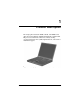
1 Product Description The Compaq Evo Notebook N620c, N610c, and N600c Series offer advanced modularity, Mobile Intel Pentium 4 and Pentium III processors with 64-bit architecture, industry-leading Accelerated Graphics Port (AGP) implementation, and extensive multimedia support. Figure 1-1.
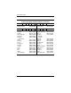
Product Description 1.1 Models Computer models are shown in Tables 1-1 through 1-4. Table 1-1 Compaq Evo Notebook N620c, N610c, and N600c Model Naming Conventions Key N610 P4 200 P4 40 V C 25 O XXXXXX-XXX 1 2 3 4 5 6 7 8 9 10 Ke y Description Options 1 Brand/Series designator N = Notebook 620 = N620c series 610 = N610c series 600 = N600c series 2 Processor type P4 = Intel Pentium 4 P3 = Intel Pentium III P = Intel Pentium-M 3 Processor speed 200 = 2.0 Ghz 190 = 1.
Product Description Table 1-1 Compaq Evo Notebook N620c, N610c, and N600c Model Naming Conventions (Continued) 8 RAM 51 = 512 MB 38 = 384 MB 25 = 256 MB 12 = 128 MB 9 Operating system 8 = Windows 98 SE 6 = Windows 2000 and Windows XP 2 = Windows 2000 O = Windows XP Pro E = Windows XP Home 10 SKU# Table 1-2 Compaq Evo Notebook N620c Models The following Evo Notebook N620c models feature: ■ Dual Stick pointing device (TouchPad and pointing stick) ■ 8-cell, 4.
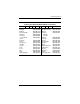
Product Description Table 1-2 Compaq Evo Notebook N620c Models (Continued) N620c P 160 Brazil French Canada N620c P Asia Pacific Australia Belgium Czech Republic Denmark European International France Germany Greece Hong Kong Hungary Iceland India Israel Italy Japan Japan (English) 1–4 P4 60 C DE272A AC4 DE272A ABC 150 P4 60 C DE271A UUF DE271A ABG DE271A UUG DE271A AKB DE271A ABY DE271A ABB DE271A ABF DE271A ABD DE271A ABV DE271A AB5 DE271A AKC DE271A A2M DE271A ACJ DE271A ABT DE271A ABZ DE27
Product Description Table 1-2 Compaq Evo Notebook N620c Models (Continued) N620c P Asia Pacific Australia Belgium Czech Republic Denmark European International France Germany Greece Hong Kong Hungary Iceland India Israel Italy Japan Japan (English) 150 P4 60 C DE270A UUF DE270A ABG DE270A UUG DE270A AKB DE270A ABY DE270A ABB DE270A ABF DE270A ABD DE270A ABV DE270A AB5 DE270A AKC DE270A A2M DE270A ACJ DE270A ABT DE270A ABZ DE270A ABJ DE270A ACF Maintenance and Service Guide G 51 O Korea The Neth
Product Description Table 1-2 Compaq Evo Notebook N620c Models (Continued) N620c P Asia Pacific Australia Belgium Brazil Czech Republic Denmark European International France French Canada Germany Greece Hong Kong Hungary Iceland India Israel Italy Japan Japan (English) 1–6 140 X4 40 C DE265A UUF DE265A ABG DE265A UUG DE265A AC4 DE265A AKB DE265A ABY DE265A ABB DE265A ABF DE265A ABC DE265A ABD DE265A ABV DE265A AB5 DE265A AKC DE265A A2M DE265A ACJ DE265A ABT DE265A ABZ DE265A ABJ DE265A ACF X 25
Product Description Table 1-2 Compaq Evo Notebook N620c Models (Continued) N620c P 140 P Denmark Germany Italy Norway C DE264A ABF DE264A ABC DE264A ABD DE264A ABV DE264A AB5 DE264A AKC DE264A A2M DE264A ACJ DE264A ABT DE264A ABZ DE264A ABJ DE264A ACF 140 X4 40 C DE269A ABY DE269A ABD DE269A ABZ DE269A ABN Denmark Germany Italy Norway N620c 40 DE264A UUF DE264A ABG DE264A UUG DE264A AC4 DE264A AKB DE264A ABY DE264A ABB Asia Pacific Australia Belgium Brazil Czech Republic Denmark European Inte
Product Description Table 1-2 Compaq Evo Notebook N620c Models (Continued) N620c P Asia Pacific Australia Belgium Brazil Czech Republic Denmark European International France French Canada Germany Greece Hong Kong Hungary Iceland India Israel Italy Japan Japan (English) 1–8 130 X4 30 C DE263A UUF DE263A ABG DE263A UUG DE263A AC4 DE263A AKB DE263A ABY DE263A ABB DE263A ABF DE263A ABC DE263A ABD DE263A ABV DE263A AB5 DE263A AKC DE263A A2M DE263A ACJ DE263A ABT DE263A ABZ DE263A ABJ DE263A ACF X 25
Product Description Table 1-2 Compaq Evo Notebook N620c Models (Continued) N620c P Asia Pacific Australia Belgium Brazil Czech Republic Denmark European International France French Canada Germany Greece Hong Kong Hungary Iceland India Israel Italy Japan Japan (English) 130 X4 30 C DE262A UUF DE262A ABG DE262A UUG DE262A AC4 DE262A AKB DE262A ABY DE262A ABB DE262A ABF DE262A ABC DE262A ABD DE262A ABV DE262A AB5 DE262A AKC DE262A A2M DE262A ACJ DE262A ABT DE262A ABZ DE262A ABJ DE262A ACF Maintenance
Product Description Table 1-3 Compaq Evo Notebook N610c Models The following Evo Notebook N610c models feature: ■ Dual Stick pointing device (TouchPad and pointing stick) ■ 8-cell, 4.0-Ah Li ion battery pack ■ 3-year warranty on parts, labor, and on-site, next business day response ■ 32 MB of discrete video memory ■ config.
Product Description Table 1-3 Compaq Evo Notebook N610c Models (Continued) The following Evo Notebook N610c models feature: ■ Dual Stick pointing device (TouchPad and pointing stick) ■ 8-cell, 4.0-Ah Li ion battery pack ■ 3-year warranty on parts and labor ■ 32 MB of discrete video memory ■ config.
Product Description Table 1-3 Compaq Evo Notebook N610c Models (Continued) N610 P4 200 P4 Belgium Czech Republic Denmark France French Canada Germany Greece/Poland Hungary Israel Italy The Netherlands 1–12 40 W 470050-987 470050-986 470050-963 470050-985 470050-964 470050-965 470054-625 Asia Pacific Australia Belgium Brazil Czech Republic Denmark European International France French Canada Germany Greece/Poland Hong Kong Hungary Israel Italy Japan Japan (English) N610 P4 470050-966 470050-961 47
Product Description Table 1-3 Compaq Evo Notebook N610c Models (Continued) N610 P4 Asia Pacific Australia Belgium Brazil Czech Republic Denmark France French Canada Germany Greece/Poland Hong Kong Hungary Israel Italy Japan Japan (English) Korea Latin America Latin America (GEM/NAFTA) 200 X4 30 V 470050-438 470050-421 470050-371 470050-419 470050-374 470050-378 470050-379 470050-358 470050-386 470050-392 470050-443 470050-393 470050-395 470050-396 470050-416 470050-417 470050-446 470050-418 470050-5
Product Description Table 1-3 Compaq Evo Notebook N610c Models (Continued) N610 P4 Asia Pacific Australia Belgium Brazil Czech Republic Denmark France French Canada Germany Greece/Poland Hong Kong Hungary Israel Italy Japan Japan (English) Korea 1–14 200 X4 30 V 470050-572 470050-571 470050-538 470050-570 470050-539 470050-541 470050-544 470050-536 470050-547 470050-548 470050-575 470050-549 470050-550 470050-552 470050-567 470050-568 470050-576 C 25 E Latin America The Netherlands Norway Peopl
Product Description Table 1-3 Compaq Evo Notebook N610c Models (Continued) N610 P4 Asia Pacific Australia Belgium Brazil Czech Republic Denmark France French Canada Germany Greece/Poland Hong Kong Hungary Israel Italy Japan Japan (English) Korea Latin America Latin America (GEM/NAFTA) 200 X4 30 V 470050-502 470050-498 470050-456 470050-497 470050-457 470050-458 470050-459 470050-454 470050-460 470050-462 470050-507 470050-468 470050-469 470050-470 470050-490 470050-491 470050-512 470050-496 470050-5
Product Description Table 1-3 Compaq Evo Notebook N610c Models (Continued) N610 P4 Asia Pacific Australia Belgium Brazil Czech Republic Denmark European International France French Canada Germany Greece/Poland Hong Kong Hungary Israel Italy Japan Japan (English) Korea Latin America Latin America (GEM/NAFTA) 1–16 180 X4 30 V 470037-572 470037-570 470037-529 470037-569 470037-530 470037-531 470048-135 470037-532 470037-527 470037-533 470037-535 470037-584 470037-537 470037-538 470037-539 470037-561 4
Product Description Table 1-3 Compaq Evo Notebook N610c Models (Continued) N610 P4 Asia Pacific Australia Belgium Brazil Czech Republic Denmark European International France French Canada Germany Greece/Poland Hong Kong Hungary Israel Italy Japan Japan (English) 180 X4 30 V 470044-442 470044-441 470044-410 470044-440 470044-411 470044-412 470048-137 470044-416 470044-408 470044-417 470044-418 470044-445 470044-419 470044-420 470044-421 470044-436 470044-438 Maintenance and Service Guide C 25 E
Product Description Table 1-3 Compaq Evo Notebook N610c Models (Continued) N610 P4 180 P4 Belgium Czech Republic Denmark France Germany Greece/Poland Hungary Israel Italy The Netherlands 1–18 30 V 470037-714 470037-713 470037-687 470037-712 470037-688 470037-689 470048-136 Asia Pacific Australia Belgium Brazil Czech Republic Denmark European International France French Canada Germany Greece/Poland Hong Kong Hungary Israel Italy Japan Japan (English) Korea Latin America Latin America (GEM/NAFTA) N6
Product Description Table 1-3 Compaq Evo Notebook N610c Models (Continued) N610 P4 180 P4 160 French Canada United States N610 P4 French Canada United States 20 D 470050-772 470050-773 470050-774 470050-775 470050-776 470050-780 470050-781 470050-782 470050-783 470050-784 Belgium Czech Republic Denmark France Germany Greece/Poland Hungary Israel Italy The Netherlands N610 X4 X4 20 V 470037-664 470037-661 160 X4 20 V 470037-736 470037-733 Maintenance and Service Guide C 25 O Norway
Product Description Table 1-3 Compaq Evo Notebook N610c Models (Continued) N610 P4 160 P4 Belgium Czech Republic Denmark France Germany Greece/Poland Hungary Israel Italy The Netherlands 1–20 20 D 470037-567 470037-571 470037-573 470037-578 470037-581 470037-585 470037-586 470037-588 470037-595 470037-601 Belgium Czech Republic Denmark France Germany Greece/Poland Hungary Israel Italy The Netherlands N610 X4 160 X4 20 D 470037-619 470037-620 470037-621 470037-622 470037-623 470037-625 470037
Product Description Table 1-4 Compaq Evo Notebook N600c Models The following Evo Notebook N600c models feature: ■ Dual Stick pointing device (TouchPad and pointing stick) ■ 8-cell, 4.0-Ah Li ion battery pack ■ 3-year warranty on parts, labor, and on-site, next business day response ■ 32 MB of discrete video memory ■ config.
Product Description Table 1-4 Compaq Evo Notebook N600c Models (Continued) N600 P3 120 P3 120 P3 120 European International N600 P3 European International 1–22 V P4 30 V 470053-561 470053-562 470053-563 470053-564 470053-565 470053-566 470053-568 470053-570 470053-571 470053-573 470053-574 470053-575 Belgium Czech Republic Denmark France Germany Greece/Poland Hungary Israel Italy The Netherlands Norway Portugal N600 30 470023-411 470023-412 470023-415 470023-416 470023-419 470023-420 4700
Product Description Table 1-4 Compaq Evo Notebook N600c Models (Continued) N600 P3 Asia Pacific Australia Belgium Brazil Czech Republic Denmark France French Canada Germany Greece/Poland Hong Kong Hungary Israel Italy Japan Japan (English) Korea Latin America The Netherlands 120 X4 30 V 470053-685 470053-686 470053-628 470053-684 470053-631 470053-640 470053-644 470053-619 470053-646 470053-649 470053-689 470053-651 470053-653 470053-655 470053-681 470053-682 470053-690 470053-683 470053-659 Mainte
Product Description Table 1-4 Compaq Evo Notebook N600c Models (Continued) N600 P3 120 P3 Greece/Poland Hungary Portugal 1–24 30 V 470053-592 470053-594 470053-624 470053-590 470053-634 470053-643 470053-645 470053-559 470053-647 470053-648 470053-603 470053-650 470053-652 470053-654 470053-585 470053-586 470053-605 470053-587 470053-658 Asia Pacific Australia Belgium Brazil Czech Republic Denmark France French Canada Germany Greece/Poland Hong Kong Hungary Israel Italy Japan Japan (English) Korea
Product Description Table 1-4 Compaq Evo Notebook N600c Models (Continued) N600 P3 100 P3 100 P3 100 European International N600 P3 European International D X4 20 D 470029-192 470029-195 470029-207 470029-212 470029-214 470029-217 470029-224 470029-227 470029-228 Belgium Czech Republic Denmark France Germany Israel Italy The Netherlands Norway N600 20 470029-930 470029-936 470029-939 470029-941 470029-945 470029-951 470029-982 470029-983 470029-984 470029-986 470029-987 470029-988 Belgium
Product Description 1.2 Features ■ 1–26 The following processors are available, varying by notebook model: ❏ The Evo Notebook N620c features an Intel Pentium-M 1.6-, 1.5-, 1.4-, or 1.3-GHz processor, with 512-KB integrated L2 cache. ❏ The Evo Notebook N610c features a Mobile Intel Pentium 4 2.0-, 1.9-, 1.8-, 1.7-, or 1.6-GHz processor, with 512-KB integrated L2 cache. ❏ The Evo Notebook N600c features a Mobile Intel Pentium III 1.066 GHz-M or 866-MHz-M processor, with 512-KB integrated L2 cache.
Product Description ■ Mini PCI 10/100 network interface card (NIC) or Mini PCI V.
Product Description 1.3 Clearing a Password If the notebook you are servicing has an unknown password, follow these steps to clear the password. These steps also clear CMOS. 1. Prepare the notebook for disassembly (refer to Section 5.3, “Preparing the Notebook for Disassembly,” for more information). 2. Remove the RTC battery (refer to Section 5.6, “Disk Cell RTC Battery”). 3. Wait approximately five minutes. 4. Replace the RTC battery and reassemble the notebook. 5. Connect AC power to the notebook.
Product Description 1.4 Power Management The notebook comes with power management features that extend battery operating time and conserve power.
Product Description 1.5 Notebook External Components The external components on the front and right side of the Evo Notebook N620c, N610c, and N600c are shown in Figure 1-2 and described in Table 1-5. . Figure 1-2. Front and Right Side Components Table 1-5 Front and Right Side Panel Components Item Component Function 1 Power light On: Power is turned on. Blinking: Notebook is in Standby.
Product Description Table 1-5 Front and Right Side Panel Components (Continued) Item Component Function 4 Media Bay light Turns on when the diskette drive in the Media Bay or the optional external diskette drive is accessed. 5 Infrared port Links to another IrDA-compliant device for wireless communication. 6 Volume control buttons Adjust the volume of the stereo speakers. 7 Stereo line-out/ headphone jack Connects stereo speakers, headphones, headset, or television audio.
Product Description The Evo Notebook N620c, N610c, and N600c right side and rear panel components are shown in Figure 1-3 and described in Table 1-6. Figure 1-3.
Product Description Table 1-6 Right Side and Rear Panel Components (Continued) Item Component Function 3 Parallel connector Connects a parallel device. 4 USB connectors (2) Connect USB devices. 5 RJ-45 jack (network models only) Connects the network cable. A network cable is not included with the notebook. 6 Serial connector Connects a serial device. 7 External monitor connector Connects an external monitor or overhead projector.
Product Description The Evo Notebook N600c right side and rear panel components are shown in Figure 1-4 and described in Table 1-7. Figure 1-4. Right Side and Rear Panel Components— Evo Notebook N600c Table 1-7 Right Side and Rear Panel Components Item Component Function 1 MultiPort Connects wireless communication devices, such as an optional Bluetooth or 802.11b MultiPort module, and other options.
Product Description Table 1-7 Right Side and Rear Panel Components (Continued) Item Component Function 3 Keyboard/mouse connector Connects an external keyboard or PS/2-compatible external mouse. To connect a keyboard and a mouse at the same time, use an optional Y-adapter. 4 Parallel connector Connects a parallel device. 5 Docking connector Connects the computer to the optional expansion base, convenience base, or port replicator. 6 Serial connector Connects a serial device.
Product Description The keyboard components of the Evo Notebook N620c, N610c, and N600c are shown in Figure 1-5 and described in Table 1-8. Figure 1-5. Keyboard Components Table 1-8 Keyboard Components Item Component Function 1 F1 through F12 function keys Perform preset functions. 2 Embedded numeric keypad Converts keys to a numeric keypad. 3 Cursor control keys Move the cursor around the screen. 4 Windows application key Displays a menu when using a Microsoft application.
Product Description The components on the top of the Evo Notebook N620c, N610c, and N600c are shown in Figure 1-6 and described in Table 1-9. Figure 1-6. Top Components Table 1-9 Top Components Item Component Function 1 Num lock light On: Num lock is on and the embedded numeric keypad is enabled. 2 Scroll lock light On: Scroll is on.
Product Description Table 1-9 Top Components (Continued) Item Component Function 3 Caps lock light On: Caps lock is on. 4 Standby button Turns on the notebook if it is off. Initiates and exits Standby. When pressed with the Fn key, initiates Hibernation. 5 Stereo speakers (2) Produce stereo sound. 6 Easy Access buttons (4) Provide quick access to the Internet. Refer to the Hardware Guide that ships with the notebook for information about these buttons. 7 Power switch Turns on the notebook.
Product Description The Evo Notebook N620c and N610c bottom components are shown in Figure 1-7 and described in Table 1-10. Figure 1-7. Bottom Components—Evo Notebook N620c and N610c Table 1-10 Bottom Components Item Component Function 1 Media Bay Accepts a diskette drive, CD- or DVD-ROM drive, or secondary battery pack. 2 Media Bay release latch Releases the Media Bay device from the connector.
Product Description Table 1-10 Bottom Components (Continued) Item Component Function 3 Serial number Identifies the notebook; needed when you call Compaq customer support. 4 Docking connector Connects the notebook to the optional expansion base, convenience base, or port replicator. 5 Air vents (2) Allow airflow to cool internal components. 6 Fan Provides airflow to cool internal components. 7 Hard drive Supports the removable primary hard drive.
Product Description The Evo Notebook N600c bottom components are shown in Figure 1-8 and described in Table 1-11. Figure 1-8. Bottom Components—Evo Notebook N600c Table 1-11 Bottom Components Item Component Function 1 Media Bay Accepts a diskette drive, optical drive, or secondary battery pack. 2 Media Bay release latch Releases the Media Bay device from the connector. 3 Vent Allows airflow to cool internal components.
Product Description Table 1-11 Bottom Components (Continued) Item Component Function 4 Fan Provides airflow to cool internal components. 5 Certificate of Authenticity label Contains the Product Key, which may need to be entered before using some Windows operating systems. 6 Hard drive security screw Secures the hard drive. 7 Memory expansion compartment cover Covers the memory expansion compartment that contains two memory expansion slots for memory expansion boards.
Product Description 1.6 Design Overview This section presents a design overview of key parts and features of the notebook. Refer to Chapter 3, “Illustrated Parts Catalog,” to identify replacement parts, and Chapter 5, “Removal and Replacement Procedures,” for disassembly steps.
2 Troubleshooting Å WARNING: Only authorized technicians trained by Compaq should repair this equipment. All troubleshooting and repair procedures are detailed to allow only subassembly/module level repair. Because of the complexity of the individual boards and subassemblies, no one should attempt to make repairs at the component level or make modifications to any printed wiring board. Improper repairs can create a safety hazard.
Troubleshooting ■ Compaq Diagnostics—A system information and diagnostic utility that is used within your Windows operating system. Use this utility whenever possible to: ❏ Display system information. ❏ Test system components. ❏ Troubleshoot a device configuration problem in Windows 2000, Windows XP Professional, or Windows XP Home. Using Computer Setup Information and settings in Computer Setup are accessed from the File, Security, or Advanced menus: 1. Turn on or restart the computer.
Troubleshooting Selecting from the File Menu Table 2-1 File Menu Select To Do This System Information ■ View identification information about the computer, a docking base, and any battery packs in the system. ■ View specification information about the processor, memory and cache size, and system ROM. Save to Floppy Save system configuration settings to a diskette. Restore from Floppy Restore system configuration settings from a diskette.
Troubleshooting Selecting from the Security Menu Table 2-2 Security Menu Select To Do This Setup Password Enter, change, or delete a setup password. (The setup password is called an administrator password in Compaq Computer Security, a program accessed from the Windows Control Panel.) Power-on Password Enter, change, or delete a power-on password. DriveLock Passwords Enable/disable DriveLock; change a DriveLock User or Master password.
Troubleshooting Selecting from the Advanced Menu Table 2-3 Advanced Menu Select To Do This Language (or press F2) Change the Computer Setup language. Boot Options Enable/disable: Device Options ■ QuickBoot, which starts the computer more quickly by eliminating some startup tests. (If you suspect a memory failure and want to test memory automatically during startup, disable QuickBoot.) ■ MultiBoot, which sets a startup sequence that can include most bootable devices and media in the system.
Troubleshooting Table 2-3 Advanced Menu (Continued) Select To Do This Device Options (continued) ■ Change the parallel port mode from Enhanced Parallel Port (EPP, the default setting) to standard, bidirectional, EPP or Enhanced Capabilities Port (ECP). ■ Set video-out mode to NTSC (default), PAL, NTSC-J, or PAL-M.* ■ Enable/disable all settings in the SpeedStep window. (When Disable is selected, the computer runs in Battery Optimized mode.
Troubleshooting 2.2 Using Compaq Diagnostics When you access Compaq Diagnostics, a scan of all system components is displayed on the screen before the Compaq Diagnostics window opens. You can display more or less information from anywhere within Compaq Diagnostics by selecting Level on the menu bar. Compaq Diagnostics is designed to test Compaq components. If non-Compaq components are tested, the results may be inconclusive. Obtaining, Saving, or Printing Configuration Information 1.
Troubleshooting Obtaining, Saving, or Printing Diagnostic Test Information 1. Access Compaq Diagnostics by selecting Start > Settings > Control Panel > Compaq Diagnostics. 2. Select the Test tab. 3. In the scroll box, select the category or device you want to test. 4. Select a test type: 2–8 ❏ Quick Test—Runs a quick, general test on each device in a selected category. ❏ Complete Test—Performs maximum testing on each device in a selected category.
Troubleshooting 5. Select a test mode: ❏ Interactive Mode—Provides maximum control over the testing process. You determine whether the test was passed or failed, and you may be prompted to insert or remove devices. ❏ Unattended Mode—Does not display prompts. If errors are found, they are displayed when testing is complete. 6. Click Begin Testing. 7. Select a tab to view a test report: ❏ Status tab—Summarizes the tests run, passed, and failed during the current testing session.
Troubleshooting 2.3 Troubleshooting Flowcharts Table 2-4 Troubleshooting Flowcharts Overview Flowchart Description 2.1 Initial Troubleshooting 2.2 No Power, Part 1 2.3 No Power, Part 2 2.4 No Power, Part 3 2.5 No Power, Part 4 2.6 No Video, Part 1 2.7 No Video, Part 2 2.8 Nonfunctioning Docking Station 2.9 No Operating System (OS) Loading 2.10 No OS Loading From Hard Drive, Part 1 2.11 No OS Loading From Hard Drive, Part 2 2.12 No OS Loading From Hard Drive, Part 3 2.
Troubleshooting Flowchart 2.1 - Initial Troubleshooting Begin troubleshooting. N Go to Flowchart 2.2, No Power, Part 1. Is there power? Y N Check LED board, speaker connections. Beeps, LEDs, or error messages? N Y Go to Flowchart 2.17, Nonfunctioning Device. All drives working? N Y Go to Flowchart 2.6, No Video, Part 1. Is there video? (no boot) N Y Keyboard/ pointing device working? N Y Go to Flowchart 2.9, No OS Loading.
Troubleshooting Flowchart 2.2 - No Power, Part 1 No power (power LED is off). Remove from docking station (if applicable). N N Power up on battery power? Go to Flowchart 2.3, No Power, Part 2. Power up on battery power? *Reset power. Y Y N N Power up on AC power? Power up on AC power? *Reset power. Y Go to Flowchart 2.4, No Power, Part 3. Y Y Power up in docking station? *On some models there is a separate reset button.
Troubleshooting Flowchart 2.3 - No Power, Part 2 Continued from Flowchart 2.2, No Power, Part 1. Visually check for debris in battery socket and clean if necessary. Y Power on? Done N Check battery by recharging, moving it to another computer, or replacing it. N Replace power supply (if applicable). Power on? Y N Done Power on? Go to Flowchart 2.4, No Power, Part 3.
Troubleshooting Flowchart 2.4 - No Power, Part 3 Continued from Flowchart 2.3, No Power, Part 2. Plug directly into AC outlet. Y Power LED on? Done N Reseat AC adapter in computer and at power source. Y Power on? Done N N Power outlet active? External Try different outlet. Y Internal or external AC adapter? N Internal Go to Flowchart 2.5, No Power, Part 4. Replace power cord. Power on? Y Y Power on? Replace external AC adapter.
Troubleshooting Flowchart 2.5 - No Power, Part 4 Continued from Flowchart 2.4, No Power, Part 3. Open computer. Y Loose or damaged parts? N Reseat loose components and boards and replace damaged items. Close computer and retest. N Power on? Y Replace the following items (if applicable). Check computer operation after each replacement: 1. Internal DC-DC converter* 2. Internal AC adapter 3. Processor board* 4.
Troubleshooting Flowchart 2.6 - No Video, Part 1 No video. Docking station *To change from internal to external display, use the hotkey combination. Go to Flowchart 2.7, No Video, Part 2. Stand-alone or docking station? Stand-alone Internal or external display*? Y Adjust brightness. A Adjust brightness. Press lid switch to ensure operation. Y Video OK? Done N Internal External Video OK? Y Video OK? Done Done N N Replace the following one at a time. Test after each replacement. 1.
Troubleshooting Flowchart 2.7 - No Video, Part 2 Continued from Flowchart 2.6, No Video, Part 1. Remove notebook from docking station, if connected. Adjust display brightness. Check brightness of external monitor. N Y Go to “A” in Flowchart 2.6, No Video, Part 1. Video OK? Y Video OK? Done N Check that notebook is properly seated in docking station, for bent pins on cable, and for monitor connection. Try another external monitor.
Troubleshooting Flowchart 2.8 - Nonfunctioning Docking Station (if applicable) Nonfunctioning docking station. Reseat power cord in docking station and power outlet. Check voltage setting on docking station. Reinstall notebook into docking station. Y Reset monitor cable connector at docking station. Docking station operating? Done N Y Docking station operating? N Remove notebook, reseat all internal parts, and replace any damaged items in docking station.
Troubleshooting Flowchart 2.9 - No Operating System (OS) Loading No OS loading.* Reseat power cord in docking station and power outlet. *Before beginning troubleshooting, always check cable connections, cable ends, and drives for bent or damaged pins. No OS loading from hard drive, go to Flowchart 2.10, No OS Loading from Hard Drive, Part 1. No OS loading from diskette drive, go to Flowchart 2.13, No OS Loading from Diskette Drive. No OS loading from CD- or DVD-ROM drive, go to Flowchart 2.
Troubleshooting Flowchart 2.10 - No OS Loading from Hard Drive, Part 1 OS not loading from hard drive. Y Nonsystem disk message? N Go to Flowchart 2.11, No OS Loading from Hard Drive, Part 2. Reseat external hard drive. Y OS loading? Done N N Boot from CD? N Y Boot from diskette? Check the setup utility for correct booting order. Y N Go to Flowchart 2.13, No OS Loading from Diskette Drive. Change boot priority through the setup utility and reboot.
Troubleshooting Flowchart 2.11 - No OS Loading from Hard Drive, Part 2 Continued from Flowchart 2.10, No OS Loading from Hard Drive, Part 1. Reseat hard drive. N 1. Replace hard drive. 2. Replace system board. CD or diskette in drive? Y Hard drive accessible? Y Done N Remove diskette and reboot. Run FDISK. Y Boot from hard drive? N Done N Create partition, then format hard drive to bootable C:\ prompt. Hard drive partitioned? Y N N Go to Flowchart 2.13, No OS Loading from Diskette Drive.
Troubleshooting Flowchart 2.12 - No OS Loading from Hard Drive, Part 3 Continued from Flowchart 2.11, No OS Loading from Hard Drive, Part 2. N System files on hard drive? Install OS and reboot. Y Y Y Virus on hard drive? OS loading from hard drive? Clean virus. N Done N Y Run SCANDISK and check for bad sectors. Diagnostics on diskette? Replace hard drive. N N Can bad sectors be fixed? Run diagnostics and follow recommendations. Replace hard drive. Y N Fix bad sectors.
Troubleshooting Flowchart 2.13 - No OS Loading from Diskette Drive Y OS not loading from diskette drive. Reseat diskette drive. OS loading? Done N N Y Install bootable diskette and reboot computer. Bootable diskette in drive? Nonsystem disk message? N Y N Check diskette for system files. Try different diskette. Go to Flowchart 2.17, Nonfunctioning Device. Boot from another device? Y N Diskette drive enabled in the setup utility? Y Enable drive and cold boot computer. Y 1.
Troubleshooting Flowchart 2.14 - No OS Loading from CD- or DVD-ROM Drive Y No OS loading from CD- or DVD-ROM Drive. N Bootable disc in drive? Disc in drive? Y N Install bootable disc and reboot computer. Try another bootable disc. Install bootable disc. Y Boots from CD or DVD? Done N Y Reseat drive. Boots from CD or DVD? Done N N Booting from another device? Y Y Booting order correct? N Go to Flowchart 2.17, Nonfunctioning Device. Clear CMOS. Refer to Section 1.
Troubleshooting Flowchart 2.15 - No Audio, Part 1 Y Turn up audio internally or externally. No audio. Audio? Done N Y Notebook in docking station (if applicable)? N N Go to Flowchart 2.16, No Audio, Part 2. Internal audio? Undock Y Replace the following docking station components one at a time as applicable. Check after each change. Go to Flowchart 2.16, No Audio, Part 2. 1. Reseat docking station audio cable. 2. Replace audio cable. 3. Replace speaker. 4. Replace docking station audio board.
Troubleshooting Flowchart 2.16 - No Audio, Part 2 Continued from Flowchart 2.15, No Audio, Part 1. N Audio driver in OS configured? Reload audio drivers. Y N Load drivers and set configuration in OS. Correct drivers for application? Y Connect to external speaker. N Audio? Y Replace audio board and speaker connections in notebook (if applicable). Y Audio? Done N 1. Replace internal speakers. 2. Replace audioboard(if applicable). 3. Replace system board.
Troubleshooting Flowchart 2.17 - Nonfunctioning Device Nonfunctioning device. Reseat device. Unplug the nonfunctioning device from the notebook and inspect cables and plugs for bent or broken pins or other damage. Y Clear CMOS. Any physical device detected? Fix or replace broken item. Possible bad hard drive. Replace drive. Go to Flowchart 2.9, No OS Loading. N Reattach device. Close notebook, plug in power, and reboot.
Troubleshooting Flowchart 2.18 - Nonfunctioning Keyboard Keyboard not operating properly. Connect notebook to good external keyboard. N Replace system board. External device works? Y Reseat internal keyboard connector (if applicable). N Replace internal keyboard or cable. OK? Y Y OK? Done Done N Replace system board.
Troubleshooting Flowchart 2.19 - Nonfunctioning Pointing Device Pointing device not operating properly. Connect notebook to good external pointing device. N External device works? Replace system board. Y Reseat internal pointing device connector (if applicable). N Replace internal pointing device or cable. OK? Y Y OK? Done Done N Replace system board.
Troubleshooting Flowchart 2.20 - No Network or Modem Connection No network or modem connection. N Network or modem jack active? Replace jack or have jack activated. Y Y Connect to nondigital line. Digital line? N N NIC/modem configured in OS? Y Reload drivers and reconfigure. OK? Done N Y Disconnect all power from the notebook and open. Replace NIC/modem (if applicable). Y Reseat NIC/modem (if applicable). OK? Done N Replace system board.
3 Illustrated Parts Catalog This chapter provides an illustrated parts breakdown and a reference for spare part numbers and option part numbers. 3.1 Serial Number Location When ordering parts or requesting information, provide the notebook serial number and model number located on the bottom of the notebook (Figure 3-1). Figure 3-1.
Illustrated Parts Catalog 3.2 Notebook System Major Components Figure 3-2.
Illustrated Parts Catalog Table 3-1 Spare Parts: Notebook System Major Components Item Description 1 Displays Spare Part Number For use with Evo Notebook N620c models only 14.1-inch, SXGA+, CTFT 319733-001 For use with Evo Notebook N610c models only: 14.1-inch, SXGA+, CTFT 14.1-inch, XGA, CTFT 291261-001 291262-001 For use with Evo Notebook N600c models only: 14.1-inch, SXGA+, CTFT 14.
Illustrated Parts Catalog Notebook System Major Components (continued) 3–4 Maintenance and Service Guide
Illustrated Parts Catalog Table 3-1 Spare Parts: Notebook System Major Components (Continued) Spare Part Number Item Description 3 Keyboard without pointing stick (for use with TouchPad models) Arabic BosniaHerzegovina/ Croatia/ Slovenia/ Yugoslavia Brazilian Czech Danish European French French Canadian German Greek Hebrew Hungarian 241428-171 241428-B41 241428-201 241428-181 241428-221 241428-021 241428-051 241428-121 241428-041 241428-151 241428-BB1 241428-211 Maintenance and Service Guide Intern
Illustrated Parts Catalog Notebook System Major Components (continued) 3–6 Maintenance and Service Guide
Illustrated Parts Catalog Table 3-1 Spare Parts: Notebook System Major Components (Continued) Item 4a 4b 4c 4d 4e 4f 5 Description Spare Part Number Miscellaneous Plastics Kit 241439-001 Memory expansion compartment cover (on Evo Notebook N620c and N610c models) Mini PCI compartment cover (on Evo Notebook N600c models) Processor bracket Modem cable Hard drive bezel Disk cell RTC battery Mini PCI compartment cover (on Evo Notebook N620c and N610c models) Memory expansion compartment cover (on Evo N
Illustrated Parts Catalog Notebook System Major Components (continued) 3–8 Maintenance and Service Guide
Illustrated Parts Catalog Table 3-1 Spare Parts: Notebook System Major Components (Continued) Item Description 6 Memory expansion boards 7 266 MHz, 2DM (for Evo Notebook N620c models only) 1024 MB 768 MB 512 MB 384 MB 256 MB 301576-001 301575-001 301574-001 301572-001 301571-001 133 MHz (for Evo Notebook N610c models only) 512 MB 256 MB 128 MB 64 MB 238879-001 212683-001 212682-001 212681-001 100 MHz (for Evo Notebook N600c models only) 512 MB 256 MB 128 MB 280875-001 280874-001 280873-001 Top
Illustrated Parts Catalog Notebook System Major Components (continued) 3–10 Maintenance and Service Guide
Illustrated Parts Catalog Table 3-1 Spare Parts: Notebook System Major Components (Continued) Item Description 9 System boards For use with Evo Notebook N620c models only For use with Evo Notebook N610c models only For use with Evo Notebook N600c models only: Mobile Intel Pentium III processor 1.
Illustrated Parts Catalog Notebook System Major Components (continued) 3–12 Maintenance and Service Guide
Illustrated Parts Catalog Table 3-1 Spare Parts: Notebook System Major Components (Continued) Item Description 14 Hard drives 15 For use with Evo Notebook N620c models only: 60 GB, 5400 RPM 60 GB, 4200 RPM 40 GB, 5400 RPM 40 GB, 4200 RPM 309475-001 309474-001 309473-001 309472-001 For use with Evo Notebook N610c models only: 40 GB 30 GB 20 GB 265495-001 257660-001 235540-101 For use with Evo Notebook N600c models only: 30 GB 20 GB 15 GB 10 GB 217096-001 235421-001 241429-001 217094-001 Mini PCI
Illustrated Parts Catalog Notebook System Major Components (continued) 3–14 Maintenance and Service Guide
Illustrated Parts Catalog Table 3-1 Spare Parts: Notebook System Major Components (Continued) Item Description 17 Media Bay devices For use with all Evo Notebook N620c, N610c, and N600c models: Diskette drive 24X Max CD-ROM drive 8X Max CD-RW drive 8X Max DVD-ROM drive DVD/CD-RW combination drive 2X Max SuperDisk LS120 drive IOmega 250-MB ZIP drive MultiBay battery pack, 6 cell MultiBay battery pack, 3.
Illustrated Parts Catalog 3.
Illustrated Parts Catalog Table 3-2 Miscellaneous Plastics Kit Components Spare Part Number 241439-001 Item Description 1 Memory expansion compartment cover (Evo Notebook N620c and N610c models) Mini PCI compartment cover (Evo Notebook N600c models) 2 Mini PCI compartment cover (Evo Notebook N620c and N610c models) Memory expansion compartment cover (Evo Notebook N600c models) 3 PC Card slot space savers 4 Processor bracket 5 Hard drive bezel 6 MultiPort module cover 7 Disk cell RTC battery
Illustrated Parts Catalog 3.4 Mass Storage Devices Figure 3-4.
Illustrated Parts Catalog l Table 3-3 Mass Storage Devices Item Description 1 Hard drives Spare Part Number For use with Evo Notebook N620c models only: 60 GB, 5400 RPM 60 GB, 4200 RPM 40 GB, 5400 RPM 40 GB, 4200 RPM 309475-001 309474-001 309473-001 309472-001 For use with Evo Notebook N610c models only: 40 GB 30 GB 20 GB 265495-001 257660-001 235540-101 For use with Evo Notebook N600c models only: 30 GB 20 GB 15 GB 10 GB 217096-001 235421-001 241429-001 217094-001 2a 2b Diskette drive Extern
Illustrated Parts Catalog Mass Storage Devices (continued) 3–20 Maintenance and Service Guide
Illustrated Parts Catalog l Table 3-3 Mass Storage Devices (Continued) Item Description 4 Optical drives For use with all Evo Notebook N620c, N610c, and N600c models: Diskette drive 24X Max CD-ROM drive 8X Max CD-RW drive 8X Max DVD-ROM drive DVD/CD-RW combination drive 2X Max SuperDisk LS120 drive Iomega 250-MB ZIP drive MultiBay battery pack, 6 cell MultiBay battery pack, 3.
Illustrated Parts Catalog 3.
Illustrated Parts Catalog Table 3-4 Spare Parts: Miscellaneous (not illustrated) (Continued) Spare Part Number Description Power cord, black, 6 feet 246959-011 246959-081 246959-021 246959-061 246959-291 246959-AD1 246959-AG1 246959-031 246959-001 Australian Danish European/Middle Eastern/African Italian Japanese Korean Swiss U.K. English U.S.
4 Removal and Replacement Preliminaries This chapter provides essential information for proper and safe removal and replacement service. 4.1 Tools Required You will need the following tools to complete the removal and replacement procedures: ■ Magnetic screwdriver ■ Phillips P0 screwdriver ■ 7.0-mm socket wrench (for Evo Notebook N600c models) ■ Tool kit (includes connector removal tool, loopback plugs, and case utility tool) 4.
Removal and Replacement Preliminaries Plastic Parts Using excessive force during disassembly and reassembly can damage plastic parts. Use care when handling the plastic parts. Apply pressure only at the points designated in the maintenance instructions. Cables and Connectors Cables must be handled with extreme care to avoid damage. Apply only the tension required to unseat or seat the cables during removal and insertion. Handle cables by the connector whenever possible.
Removal and Replacement Preliminaries ■ Before handling a drive, ensure that you are discharged of static electricity. While handling a drive, avoid touching the connector. ■ Handle drives on surfaces that have at least one inch of shock-proof foam. ■ Avoid dropping drives from any height onto any surface. ■ After removing a hard drive, CD-ROM drive, or a diskette drive, place it in a static-proof bag.
Removal and Replacement Preliminaries 4.5 Packaging and Transporting Precautions Use the following grounding precautions when packaging and transporting equipment: ■ To avoid hand contact, transport products in static-safe containers, such as tubes, bags, or boxes. ■ Protect all electrostatic-sensitive parts and assemblies with conductive or approved containers or packaging. ■ Keep electrostatic-sensitive parts in their containers until the parts arrive at static-free workstations.
Removal and Replacement Preliminaries ■ When using fixtures that must directly contact dissipative surfaces, only use fixtures made of static-safe materials. ■ Keep the work area free of nonconductive materials, such as ordinary plastic assembly aids and Styrofoam. ■ Handle electrostatic-sensitive components, parts, and assemblies by the case or PCM laminate. Handle these items only at static-free workstations. ■ Avoid contact with pins, leads, or circuitry.
Removal and Replacement Preliminaries Other grounding equipment recommended for use in preventing electrostatic damage includes: 4–6 ■ Antistatic tape ■ Antistatic smocks, aprons, and sleeve protectors ■ Conductive bins and other assembly or soldering aids ■ Nonconductive foam ■ Conductive tabletop workstations with ground cords of one-megohm resistance ■ Static-dissipative tables or floor mats with hard ties to the ground ■ Field service kits ■ Static awareness labels ■ Material-handlin
Removal and Replacement Preliminaries Table 4-1 shows how humidity affects the electrostatic voltage levels generated by different activities.
5 Removal and Replacement Procedures This chapter provides removal and replacement procedures. Both Phillips P0 and Torx T8 screws are removed during disassembly. There are 38 screws and screwlocks, in seven different sizes, that must be removed and replaced when servicing the notebook. Make special note of each screw size and location during removal and replacement. Refer to Appendix C, “Screw Listing,” for detailed information on screw sizes, locations, and usage.
Removal and Replacement Procedures 5.1 Serial Number Report the notebook serial number to Compaq when requesting information or ordering spare parts. The serial number is located on the bottom of the notebook (Figure 5-1). Figure 5-1. Serial Number Location 5.2 Disassembly Sequence Chart Use the chart below to determine the section number to be referenced when removing notebook components. Disassembly Sequence Chart # of Screws Removed Section Description 5.
Removal and Replacement Procedures Disassembly Sequence Chart (Continued) # of Screws Removed Section Description 5.3 Preparing the Notebook for Disassembly (Continued) Media Bay Device 0 Hard Drive 1 to remove hard drive 2 to remove hard drive bezel 5.4 Computer Feet 0 5.5 Mini PCI Communications Board 2 5.6 Disk Cell Real Time Clock (RTC) Battery 0 5.7 Keyboard 1 5.8 Memory Expansion 0 5.9 TouchPad 0 5.10 Switch Cover 2 5.11 Display 3 5.12 Top Cover 13 5.
Removal and Replacement Procedures 5.3 Preparing the Notebook for Disassembly Perform the following steps before disassembling the notebook: 1. Turn off the notebook. 2. Disconnect the AC adapter and all external devices. Battery Pack, 6-cell, Li ion Spare Part Number Information Battery packs, 6-cell, Li ion 232633-001 and 301952-001 3. Remove the battery pack by following these steps: a. Turn the notebook bottom side up with the front facing forward.
Removal and Replacement Procedures b. Slide the battery release latch 1 toward the back of the notebook (Figure 5-2). c. Swing the right side of the battery pack up and to the left 2. d. Remove the battery pack 3. Figure 5-2. Removing the Battery Pack Reverse the preceding procedure to install the battery pack.
Removal and Replacement Procedures Media Bay Devices Spare Part Number Information For use with all Evo Notebook N620c, N610c, and N600c models: Diskette drive 24X Max CD-ROM drive 8X Max CD-RW drive 8X Max DVD-ROM drive DVD/CD-RW combination drive 2X Max SuperDisk LS120 drive Iomega 250-MB ZIP drive 6-cell battery pack For use with Evo Notebook N620c and N610c models only: 16X Max CD-RW drive 24X Max DVD/CD-RW combination drive 5–6 135233-001 228746-001 and 228746-001 153992-001 173949-001 238878-001
Removal and Replacement Procedures 4. Remove a Media Bay device by following these steps: a. Turn the notebook bottom side up with the left side facing forward. b. Slide and hold the Media Bay release latch toward the back of the notebook 1 (Figure 5-3). c. Use the notch in the Media Bay device to slide the device out of the Media Bay 2. Figure 5-3. Removing a Media Bay Device Reverse the preceding procedure to install the Media Bay device.
Removal and Replacement Procedures Hard Drive Spare Part Number Information For use with Evo Notebook N620c models only: 60 GB, 5400 RPM 60 GB, 4200 RPM 40 GB, 5400 RPM 40 GB, 4200 RPM 309475-001 309474-001 309473-001 309472-001 For use with Evo Notebook N610c models only: 40 GB 30 GB 20 GB 265495-001 257660-001 235540-101 For use with Evo Notebook N600c models only: 30 GB 20 GB 15 GB 10 GB 217096-001 235421-001 241429-001 217094-001 5. Remove the hard drive by following these steps: a.
Removal and Replacement Procedures b. Remove the PM2.5 × 2.5 hard drive retention screw 1 (Figure 5-4). c. Separate the hard drive bezel 2. d. Use the bezel to slide the hard drive forward 3 to unseat the hard drive connector from the system board. e. Remove the hard drive. Figure 5-4. Removing the Hard Drive Reverse the preceding procedure to install the hard drive.
Removal and Replacement Procedures 6. Loosen the two PM1.5 × 3.5 screws 1 that secure the hard drive bezel to the hard drive (Figure 5-5). 7. Remove the hard drive bezel from the hard drive 2. Figure 5-5. Removing the Hard Drive Bezel hard drive bezel is included in the Miscellaneous Plastics Kit, ✎ The spare part number 241439-001. Reverse the preceding procedure to install the hard drive bezel.
Removal and Replacement Procedures 5.4 Computer Feet The notebook feet are adhesive-backed rubber pads. The notebook feet are included in the Miscellaneous Plastics Kit (spare part number 241439-001). Refer to Figure 5-6 for notebook feet locations. Figure 5-6.
Removal and Replacement Procedures 5.5 Mini PCI Communications Board Evo Notebook N600c models contain a memory ✎ Compaq expansion slot in this location. Refer to Section 5.8, steps 5 and 6, for instructions on removing a memory expansion board. The mini PCI compartment cover is included in the Miscellaneous Plastics Kit (spare part number 241439-001).
Removal and Replacement Procedures 3. Remove the two PM2.5 × 5.0 screws 1 that secure the mini PCI compartment cover to the base enclosure (Figure 5-7). 4. Lift the left edge of the cover and swing it up and to the right 2. 5. Remove the cover. mini PCI compartment cover is included in the ✎ The Miscellaneous Plastics Kit (spare part number 241439-001). Figure 5-7.
Removal and Replacement Procedures 6. Disconnect the modem cable from the mini PCI communications board 1 (Figure 5-8). 7. Spread the retaining tabs 2 to release the mini PCI communications board. The board tilts up at a 45-degree angle. 8. Remove the board by pulling it away from the connector at a 45-degree angle 3. Figure 5-8. Removing the Mini PCI Communications Board Reverse the preceding procedure to install the mini PCI communications board and mini PCI compartment cover.
Removal and Replacement Procedures 5.6 Disk Cell RTC Battery disk cell RTC battery on the Compaq Evo Notebook N600c ✎ The model is located under the memory expansion slot compartment cover. Refer to Section 5.8 for instructions on removing the memory expansion slot cover. The procedures used to remove an RTC battery are the same for the Evo Notebook N620c, N610c, and N600c. The disk cell RTC battery is included in the Miscellaneous Plastics Kit (spare part number 241439-001). 1.
Removal and Replacement Procedures 3. Use a flat blade tool to remove the battery 1 from the socket on the system board (Figure 5-9). system ROM 2 is also accessible when the mini PCI ✎ The compartment cover is removed. Figure 5-9. Removing the Disk Cell RTC Battery notebook uses a CR1220 lithium disk cell battery. When ✎ The replacing the RTC battery, insert the battery with the “+” sign facing up.
Removal and Replacement Procedures 5.
Removal and Replacement Procedures Keyboard Spare Part Number Information (Continued) Keyboard without Pointstick (for use with TouchPad models) Arabic BosniaHerzegovina/ Croatia/ Slovenia/ Yugoslavia Brazilian Belgian Czech Danish European French French Canadian German Greek Hebrew Hungarian 5–18 241428-171 241428-B41 241428-201 241428-181 241428-221 241428-081 241428-021 241428-051 241428-121 241428-041 241428-151 241428-BB1 241428-211 International Italian Japanese Korean Latin American Spanish Norw
Removal and Replacement Procedures 1. Prepare the notebook for disassembly (Section 5.3). 2. Turn the notebook bottom side up with the front facing you. 3. Remove the TM2.5 × 7.0 screw that secures the keyboard to the base enclosure (Figure 5-10). Figure 5-10. Removing the Keyboard Screw 4. Turn the notebook top side up with the front facing you. 5. Open the notebook.
Removal and Replacement Procedures 6. Slide the four tabs on the top of the keyboard forward (Figure 5-11). Figure 5-11.
Removal and Replacement Procedures 7. Lift the top edge of the keyboard and swing it up and forward until it rests on the top cover 1 (Figure 5-12). 8. Disengage the keyboard cable from the retaining clips in the top cover. 9. Release the ZIF connector to which the pointing device cable is attached 2 and disconnect the pointing device cable 3. 10. Release the ZIF connector to which the keyboard cable is attached 4 and disconnect the keyboard cable 5. Figure 5-12.
Removal and Replacement Procedures 5.8 Memory Expansion Evo Notebook N600c models contain the mini PCI ✎ Compaq communications board slot in this location. Refer to Section 5.5, steps 6 through 8, for instructions on removing a mini PCI communications board. The memory expansion compartment cover is included in the Miscellaneous Plastics Kit (spare part number 241439-001).
Removal and Replacement Procedures 1. Prepare the notebook for disassembly (Section 5.3). 2. Remove the keyboard (Section 5.7). 3. Lift the left side of the memory expansion compartment cover 1 and swing the cover forward 2 (Figure 5-13). 4. Remove the memory expansion compartment cover. Figure 5-13.
Removal and Replacement Procedures 5. Spread the retaining tabs 1 that secure the memory expansion board to the socket. The board rises up at a 45-degree angle (Figure 5-14). 6. Pull the board away from the socket at a 45-degree angle 2. Figure 5-14. Removing a Memory Expansion Board Reverse the preceding procedure to replace a memory expansion board.
Removal and Replacement Procedures 5.
Removal and Replacement Procedures 4. Lift up on the left side of the TouchPad 1 until it disengages from the top cover (Figure 5-15). 5. Swing the TouchPad up and back 2 and rest it on the top cover. 6. Disconnect the TouchPad cables 3 and 4 from the system board. Figure 5-15. Removing the TouchPad 7. Remove the TouchPad. Reverse the preceding procedure to replace the TouchPad.
Removal and Replacement Procedures 5.10 Switch Cover Switch Cover Spare Part Number Information Switch cover 241438-001 1. Prepare the notebook for disassembly (Section 5.3). 2. Remove the keyboard (Section 5.7). 3. Position the notebook so the rear panel faces you. 4. Remove the two black TM2.5 × 7.0 screws that secure the switch cover to the base enclosure (Figure 5-16). Figure 5-16.
Removal and Replacement Procedures 5. Position the notebook so the front faces you. 6. Open the notebook as far as it will open. 7. Lift the switch cover up 1, slide it forward 2, and rest it on the top cover (Figure 5-17). 8. Disconnect the left 3 and right speaker cables 4 from the system board. Figure 5-17. Removing the Switch Cover 9. Remove the switch cover. Reverse the preceding procedure to replace the switch cover.
Removal and Replacement Procedures 5.11 Display Display Spare Part Number Information For use with Evo Notebook N620c models only 14.1-inch, SXGA+, CTFT 319733-001 For use with Evo Notebook N610c models only: 14.1-inch, SXGA+, CTFT 14.1-inch, XGA, CTFT 291261-001 291262-001 For use with Evo Notebook N600c models only: 14.1-inch, SXGA+, CTFT 14.1-inch, XGA, CTFT 241433-001 241434-001 1. Prepare the notebook for disassembly (Section 5.3). 2. Remove the keyboard (Section 5.7). 3.
Removal and Replacement Procedures 5. Remove the TM2.5 × 7.0 screw that secures the display ground cable to the top cover 1 (Figure 5-18). 6. Disconnect the display video 2 and inverter cables 3 from the system board. Figure 5-18. Disconnecting the Display Cables 7. Partially close the notebook. 8. Position the notebook so the rear panel faces you.
Removal and Replacement Procedures 9. Remove the two TM2.5 × 7.0 screws 1 that secure the display to the base enclosure (Figure 5-19). 10. Lift the display straight up and remove it from the base enclosure 2. Figure 5-19. Removing the Display Reverse the preceding procedure to replace the display.
Removal and Replacement Procedures 5.12 Top Cover Top Cover Spare Part Number Information For use with Evo Notebook N620c and N610c models only For use with Evo Notebook N600c models only 291264-001 241436-001 1. Prepare the notebook for disassembly (Section 5.3) and remove the following components: a. Keyboard (Section 5.7) b. Memory expansion compartment cover (Section 5.8) c. Switch cover (Section 5.10) d. Display (Section 5.11) 2. Turn the notebook bottom side up with the rear panel facing you.
Removal and Replacement Procedures 3. Remove the following screws: ❏ Three TM2.5 × 7.0 screws from the front edge of the base enclosure 1 (Figure 5-20) ❏ Two TM2.5 × 5.0 screws from the hard drive bay 2 Evo Notebook N620c contains two TM2.5 × 7.0 screws in ✎ The the hard drive bay. ❏ Two TM2.5 × 5.0 screws from the Media Bay 3 ❏ Evo Notebook N620c and N600c models—Two TM2.5 × 5.0 screws from the rear panel 4, or ❏ Evo Notebook N610c models—Two TM2.5 × 7.0 screws from the rear panel 4 Figure 5-20.
Removal and Replacement Procedures 4. Turn the notebook top side up with the front facing you. 5. For Evo Notebook N620c and N610c models only—Remove the two TM2.0 × 4.0 1 screws that secure the top cover to the base enclosure (Figure 5-21). 6. For all notebook models—Remove the TM2.5 × 7.0 2 screw that secures the top cover to the base enclosure. 7. Insert a flat blade screwdriver into the slot 3 on the rear edge of the top cover to disengage the cover from the I/O bracket. 8.
Removal and Replacement Procedures 5.13 System Board System Board Spare Part Number Information For use with Evo Notebook N620c models only For use with Evo Notebook N610c models only For use with Evo Notebook N600c models only: Mobile Intel Pentium III processor 1.
Removal and Replacement Procedures ✎ Steps 3 through 5 apply only to Evo Notebook N600c models. 3. Remove the tape that secures the modem cable to the system board 1 (Figure 5-22). 4. Remove the two 7.0-mm bushing guides 2 on either side of the docking connector that secure the system board to the base enclosure. 5. Remove the three TM2.5 × 5.0 screws 3 that secure the system board to the base enclosure. Figure 5-22.
Removal and Replacement Procedures 6 and 7 apply only to Evo Notebook N620c and ✎ Steps N610c models. 6. Remove the two TM2.5 × 5.0 screws 1 that secure the system board to the base enclosure through the rear panel (Figure 5-23). 7. Remove the three TM2.5 × 5.0 screws 2 that secure the top cover to the base enclosure. Figure 5-23.
Removal and Replacement Procedures removing the system board, do not remove the following ✎ When screws (Figure 5-24): ■ Four screws 1 that secure the processor bracket to the system board ■ Two screws 2 that secure the heat sink to the system board ■ Two screws 3 that secure the hard drive connector the system board ■ Four screws 4 that secure the PC Card assembly to the system board Figure 5-24.
Removal and Replacement Procedures 8. Use the Media Bay connector 1 to lift the right side of the system board 2 until it rests at a 45-degree angle (Figure 5-25). 9. Slide the system board out of the base enclosure at a 45-degree angle 3. Figure 5-25.
Removal and Replacement Procedures 5-26 applies only to Evo Notebook N600c models. When ✎ Figure handling the system board, be careful not to put stress on the I/O interface board 1. The narrow profile of this board makes it susceptible to being damaged when mishandled. Do not remove the screw 2 that secures the I/O interface board to the system board or attempt to remove the I/O interface board.
Removal and Replacement Procedures 5-27 applies only to Evo Notebook N620c and N610c ✎ Figure models. When handling the system board, be careful not to put stress on the I/O interface board 1. The narrow profile of this board makes it susceptible to being damaged when mishandled. The system board should only be removed and handled using the Media Bay connector 2.
Removal and Replacement Procedures 5.14 Fan Fan Spare Part Number Information For use with Evo Notebook N620c and N610c models only For use with Evo Notebook N600c models only 291266-001 255528-001 1. Prepare the notebook for disassembly (Section 5.3) and remove the following components: a. RTC battery (Section 5.6) b. Keyboard (Section 5.7) c. Memory expansion compartment cover (Section 5.8) d. TouchPad (Section 5.9) e. Switch cover (Section 5.10) f. Display (Section 5.11) g. Top cover (Section 5.
Removal and Replacement Procedures 3. Disconnect the fan cable from the system board (Figure 5-28). Figure 5-28. Disconnecting the Fan Cable 4. Turn the system board top side up with the rear panel facing you.
Removal and Replacement Procedures ✎ Steps 5 through 7 apply only to Evo Notebook N600c models. 5. Remove the PM2.0 × 4.0 screw 1 and PM2.5 × 5.0 screw 2 that secure the fan to the system board (Figure 5-29). 6. While holding the system board above the work surface, push the left side of the fan up 3 from the bottom of the system board. 7. When the left edge of the fan has cleared the system board, slide the fan to the left 4 and out of the heat sink. Figure 5-29.
Removal and Replacement Procedures 8 and 9 apply only to Evo Notebook N620c and ✎ Steps N610c models. 8. Remove the three PM2.0 × 4.0 screws 1 that secure the fan to the heat sink (Figure 5-30). 9. Lift the fan out of the heat sink 2. Figure 5-30. Removing the Fan on Evo Notebook N620c and N610c Models 10. Remove the fan. Reverse the preceding procedure to replace the fan.
Removal and Replacement Procedures 5.15 Heat Sink section applies only to Evo Notebook N620c and ✎ This N610c models. Heat Sink Spare Part Number Information Heat sink 303103-001 1. Prepare the notebook for disassembly (Section 5.3) and remove the following components: a. RTC battery (Section 5.6) b. Keyboard (Section 5.7) c. Memory expansion compartment cover (Section 5.8) d. TouchPad (Section 5.9) e. Switch cover (Section 5.10) f. Display (Section 5.11) g. Top cover (Section 5.12) h.
Removal and Replacement Procedures 2. Turn the system board bottom side up with the rear panel facing you. 3. Disconnect the fan cable from the system board (Figure 5-31). Figure 5-31.
Removal and Replacement Procedures 4. Turn the system board top side up with the rear panel facing you. 5. Remove the six PM2.0 × 4.0 screws 1 that secure the processor mounting bracket and heat sink to the system board (Figure 5-32). 6. Remove the processor mounting bracket 2. Figure 5-32.
Removal and Replacement Procedures 7. Lift the system board straight up 1. The heat sink 2 will remain resting on the work surface (Figure 5-33). Figure 5-33. Removing the Heat Sink Reverse the preceding procedure to replace the heat sink.
Removal and Replacement Procedures 5.16 Processor section applies only to Evo Notebook N620c and ✎ This N610c models. Processor Spare Part Number Information For use only with Evo Notebook N620c models Intel Pentium-M 1.6 GHz Intel Pentium-M 1.5 GHz Intel Pentium-M 1.4 GHz Intel Pentium-M 1.3 GHz 319777-001 319776-001 319775-001 319774-001 For use only with Evo Notebook N610c models Mobile Intel Pentium 4 2.0 GHz Mobile Intel Pentium 4 1.8 GHz Mobile Intel Pentium 4 1.7 GHz Mobile Intel Pentium 4 1.
Removal and Replacement Procedures 2. Turn the system board bottom side up with the rear panel facing you. 3. Insert the tip of a flat-blade screwdriver into the slot on the processor locking screw. 4. Turn the screwdriver counterclockwise 1 to release the processor (Figure 5-34). 5. Remove the processor from the socket on the system board 2. installing the processor, make sure the gold triangle 3 is in ✎ When the lower right corner. Figure 5-34.
Removal and Replacement Procedures 5.17 DC-DC Converter Board DC-DC Converter Board Spare Part Number Information For use with Evo Notebook N620c models only For use with Evo Notebook N610c models only For use with Evo Notebook N600c models only 319635-001 291263-001 241435-001 1. Prepare the notebook for disassembly (Section 5.3) and remove the following components: a. RTC battery (Section 5.6) b. Keyboard (Section 5.7) c. Memory expansion compartment cover (Section 5.8) d. TouchPad (Section 5.9) e.
Removal and Replacement Procedures 3. Lift the left and right edges of the DC-DC converter board to disconnect the board from the system board (Figure 5-35). Figure 5-35. Removing the DC-DC Converter Board 4. Remove the DC-DC converter board. Reverse the preceding procedure to replace the DC-DC converter board.
Removal and Replacement Procedures 5.18 Modem Cable modem cable is spared with the base enclosure. Modem ✎ The cables are also included in the Miscellaneous Plastics Kit (spare part number 241439-001). 1. Prepare the notebook for disassembly (Section 5.3) and remove the following components: a. RTC battery (Section 5.6) b. Keyboard (Section 5.7) c. Memory expansion compartment cover (Section 5.8) d. TouchPad (Section 5.9) e. Switch cover (Section 5.10) f. Display (Section 5.11) g. Top cover (Section 5.
Removal and Replacement Procedures 3. Lift the modem connector out of the base enclosure 1 and disengage the modem cable 2 from the alignment clips and tabs in the base enclosure (Figure 5-36). Figure 5-36. Removing the Modem Cable 4. Remove the modem cable.
Removal and Replacement Procedures installing the modem cable, route the cable along the path ✎ When indicated in Figure 5-37. Figure 5-37.
6 Specifications This chapter provides physical and performance specifications. Table 6-1 Notebook Dimensions Height Width Depth 3.1 cm 30.7 cm 25.0 cm 1.2 in 12.1 in 9.8 in 2.5 kg 5.5 lb 2.1 kg 4.8 lb Weight With 8-cell battery pack and optical drive in Media Bay With 8-cell battery pack and Media Bay weight saver Stand-alone (battery) power requirements Nominal operating voltage (Li ion) Average operating power Peak operating power Power in Suspend Power in Hibernation 14.4 V 15.
Specifications Table 6-1 Notebook (Continued) Temperature Operating Nonoperating 10° C to 35° C -20° C to 60° C 50° F to 95° F -4° F to 140° F Relative humidity (noncondensing) Operating Nonoperating 10 to 90% 5 to 95%, 38.7° C/101.6° F maximum wetbulb Altitude (unpressurized) Operating Nonoperating 0 to 3,048 m 0 to 9,144 m 0 to 10,000 ft 0 to 30,000 ft Shock Operating Nonoperating 10 G for 11 ms, half sine 60 G for 11 ms, half sine Vibration Operating Nonoperating 0.
Specifications Table 6-2 14.1-inch XGA, TFT Display Dimensions Height Depth Width 21.40 cm 28.50 cm 35.81 cm Number of colors Up to 16.8 million Contrast ratio 150:1 Brightness 120 nits typical 8.46 in 11.22 in 14.10 in Pixel resolution Pitch Format Configuration 0.264 × 0.264 mm 1024 × 768 RGB vertical stripe Backlight Edge lit Character display 80 × 25 Refresh 60 Hz Total power consumption 4.
Specifications Table 6-3 Hard Drives 40.0 GB 30.0 GB 20.0 GB 15.0 GB User capacity per drive1 40.0 30.0 GB 20.0 GB 15.0 GB Drive height 9.5 mm 9.5 mm 9.5 mm 9.5 mm Drive width 70.0 mm 70.0 mm 70.0 mm 70.0 mm Interface type ATA-5 ATA-5 ATA-5 ATA-4 Seek times (typical read, including setting) Single track Average Full stroke User addressable sectors3 2.5 ms 12.0 ms 23.0 ms 2.5 ms 12.0 ms 23.0 ms 2.5 ms 12.0 ms 23.0 ms 2.5 ms 13.0 ms 24.
Specifications Table 6-3 Hard Drives (Continued) 40.0 GB 30.0 GB 20.0 GB 15.0 GB 22,784 4 293 to 560 25,800 2 398 to 731 22,784 4 293 to 560 25,800 2 398 to 731 512 512 512 512 2 MB 512 KB 512 KB 512 KB 4200 rpm 4200 rpm 4200 rpm 4200 rpm 66.6 100 66.
Specifications Table 6-4 Diskette Drive Diskette size 3.5 in Light On system Height 12.7 mm Bytes per sector 512 0.5 in Sectors per track High density Low density 18 (1.44 MB) 9 15 (1.
Specifications Table 6-5 CD-ROM Drive Applicable disc CD-ROM (Mode 1, 2, and 3) CD-XA ready (Mode 2, Form 1 and 2) CD-I ready (Mode 2, Form 1 and 2) CD-R (read only) CD Plus Photo CD (single/multisession) CD-Extra Video CD CD-WO (fixed packets only) CD-Bridge Center hole diameter 1.5 cm Disc diameter 12 cm, 8 cm Disc thickness 1.2 mm Track pitch 1.6 µm 0.
Specifications Table 6-6 DVD-ROM Drive Applicable disc DVD-5, DVD-9, DVD-10 CD-ROM (Mode 1 and 2) CD Digital Audio CD-XA ready (Mode 2, Form 1 and 2) CD-I ready (Mode 2, Form 1 and 2) CD-R (read only) CD Plus Photo CD (single/multisession) CD-Bridge Center hole diameter 1.5 cm Disc diameter 12 cm, 8 cm Disc thickness 1.2 mm Track pitch 0.74 µm 0.59 in Access time Random Full stroke < 150 ms < 225 ms Audio output level Line-out, 0.
Specifications Table 6-7 CD-RW Drive Center hole diameter 0.39 cm Disk diameter 12 cm, 8 cm Disk thickness 0.12 cm Track pitch 0.74 µm 0.59 in 0.47 in Access time Random Full stroke < 150 ms < 225 ms Audio output level Line-out, 0.7 Vrms Cache buffer 128 KB/s minimum Data transfer rate Sustained, 16X Sustained, 4X CD-RW Normal PIO Mode 4 (single burst) 150 KB/s 5,520 KB/s 16.
Specifications Table 6-8 AC Adapter Dimensions Height Depth Width Weight 2.79 cm 3.61 cm 9.40 cm 1.10 in 1.42 in 3.70 in 0.18 kg 0.39 lb Power supply (input) Operating voltage Operating current Operating frequency range Maximum transient 90 to 260 VAC RMS nominal 1.3 A RMS 47 to 63 Hz nominal 4/50 kV Table 6-9 8-cell, Li ion Battery Pack Dimensions Length Width Depth Weight 125.80 cm 88.00 cm 20.40 cm 0.43 kg 4.95 in 3.46 in 0.80 in 0.96 lb Energy Voltage Amp-hour capacity Watt-hour capacity 14.
Specifications Table 6-10 System DMA Hardware DMA System Function DMA0 Available for audio DMA1 Entertainment audio (default; alternate = DMA0, DMA3, none) DMA2 Diskette drive DMA3 ECP parallel port LPT1 (default; alternate = DMA0, none) DMA4 DMA controller cascading (not available) DMA5 Available for PC Card DMA6 Not assigned DMA7 Not assigned ✎ PC Card controller can use DMA 1, 2, or 5.
Specifications Table 6-11 System Interrupts Hardware IRQ System Function IRQ0 System timer IRQ1 Keyboard controller IRQ2 Cascaded IRQ3 COM2 IRQ4 COM1 IRQ5 Audio (default)* IRQ6 Diskette drive IRQ7 Parallel port IRQ8 Real time clock (RTC) IRQ9 Infrared IRQ10 System use IRQ11 System use IRQ12 Internal point stick or external mouse IRQ13 Coprocessor (not available to any peripheral) IRQ14 IDE interface (hard drive and optical drive) IRQ15 System use Cards may assert IRQ3, IRQ
Specifications Table 6-12 System I/O Addresses I/O Address (hex) System Function (shipping configuration) 000–00F DMA controller no. 1 010–01F Unused 020–021 Interrupt controller no.
Specifications Table 6-12 System I/O Addresses (Continued) I/O Address (hex) System Function (shipping configuration) 0A2–0BF Unused 0C0–0DF DMA controller no.
Specifications Table 6-12 System I/O Addresses (Continued) I/O Address (hex) System Function (shipping configuration) 2F0–2F7 Unused 2F8–2FF Infrared port 300–31F Unused 320–36F Unused 370–377 Secondary diskette drive controller 378–37F Parallel port (LPT1/default) 380–387 Unused 388–38B FM synthesizer - OPL3 38C–3AF Unused 3B0–3BB VGA 3BC–3BF Reserved (parallel port/no EPP support) 3C0–3DF VGA 3E0–3E1 PC Card controller in CPU 3E2–3E3 Unused 3E8–3EF Internal modem 3F0–3F7
Specifications Table 6-13 System Memory Map Size Memory Address System Function 640 KB 00000000 - 0009FFFF Base memory 128 KB 000A0000 - 000BFFFF Video memory 48 KB 000C0000 - 000CBFFF Video BIOS 160 KB 000C8000 - 000E7FFF Unused 64 KB 000E8000 - 000FFFFF System BIOS 15 MB 00100000 - 00FFFFFF Extended memory 58 MB 01000000 - 047FFFFF Super extended memory 58 MB 04800000 - 07FFFFFF Unused 2 MB 08000000 - 080FFFFF Video memory (direct access) 4 GB 08200000 - FFFEFFFF Unused 6
A Connector Pin Assignments Table A-1 Stereo Speaker/Headphone 1 2 Pin Signal Pin Signal 1 Audio out 2 Ground Table A-2 Microphone 1 2 Pin Signal Pin Signal 1 Audio in 2 Ground Maintenance and Service Guide A–1
Connector Pin Assignments Table A-3 Keyboard/Mouse 1 2 KEY 3 5 4 6 Pin Signal Pin Signal 1 Keyboard/mouse data1 4 +5 VDC 2 Keyboard/mouse data2 5 Keyboard/mouse clock1 3 Ground 6 Keyboard/mouse clock2 Table A-4 RJ-11 Modem Pin Signal Pin Signal 1 Unused 4 Unused 2 Tip 5 Unused 3 Ring 6 Unused A–2 Maintenance and Service Guide
Connector Pin Assignments Table A-5 RJ-45 Network Interface 1 3 5 7 2 4 6 8 Pin Signal Pin Signal 1 Transmit + 5 Unused 2 Transmit - 6 Receive - 3 Receive + 7 Unused 4 Unused 8 Unused Table A-6 Universal Serial Bus Pin Signal Pin Signal 1 +5 VDC 3 Data + 2 Data - 4 Ground Maintenance and Service Guide A–3
Connector Pin Assignments Table A-7 Serial 9 6 1 5 Pin Signal Pin Signal 1 Carrier detect 6 Data set ready 2 Receive data 7 Ready to send 3 Transmit data 8 Clear to send 4 Data terminal ready 9 Ring indicator 5 Signal ground A–4 Maintenance and Service Guide
Connector Pin Assignments Table A-8 External Monitor 11 15 6 10 1 5 Pin Signal Pin Signal 1 Red analog 9 +5 VDC 2 Green analog 10 Ground 3 Blue analog 11 Monitor detect 4 Not connected 12 DDC 2B data 5 Ground 13 Horizontal sync 6 Ground analog 14 Vertical sync 7 Ground analog 15 DDC2B clock 8 Ground analog Maintenance and Service Guide A–5
Connector Pin Assignments Table A-9 Parallel 25 14 1 13 Pin Signal Pin Signal 1 Strobe* 10 Acknowledge* 2 Data bit 0 11 Busy 3 Data bit 1 12 Paper out 4 Data bit 2 13 Select 5 Data bit 3 14 Auto line feed* 6 Data bit 4 15 Error* 7 Data bit 5 16 Initialize printer* 8 Data bit 6 17 Select in* 9 Data bit 7 18–25 Signal ground *Signal is active low.
Connector Pin Assignments Table A-10 Docking 30 60 90 120 1 31 61 91 Pin Signal Pin Signal 1 EBOXL 16 RDATA 2 AGND 17 TRK0 3 EBOXS1 18 WDATA 4 RED 19 WGATE 5 AGND 20 STEP 6 GREEN 21 DIR 7 AGRD 22 POWER ON 8 BLUE 23 SYS RESET 9 AGND 24 GND 10 VSYNC 25 DSKCHG 11 HSYNC 26 +5 V (VDD) 12 DDC DAT 27 AUGND 13 DDC CLK 28 XA2/L IN 14 GND 29 XA3/R IN 15 INDEX 30 MID0/MIC IN Maintenance and Service Guide A–7
Connector Pin Assignments Table A-10 Docking (Continued) 30 60 90 120 1 31 61 91 Pin Signal Pin Signal 31 AUGND 46 SRDY 32 XA0/L OUT 47 EBOXS1/GND 33 XSD/MIC SN 48 RI1 EX 34 XA1/R OUT 49 GND 35 GND 50 SLCT LD0 36 GND 51 PE LD1 37 EXPCLK2 52 ACK LD2 38 +3.
Connector Pin Assignments Table A-10 Docking (Continued) 30 60 90 120 1 31 61 91 Pin Signal Pin Signal 61 PDATA1 LD9 76 DRT1 LIIC DAT 62 PDATA2 LD10 77 DSR1 EX 63 PDATA3 LD11 78 DCD1 EX 64 GND 79 12C DATA 65 PDATA4 LD12 80 GND 66 PDATA5 LD13 81 12C CLK 67 PDATA6 LD14 82 GND 68 PDATA7 LD 15 83 HDSEL 69 GND 84 GND 70 ERROR LCLK 85 WPROT 71 RXD1 LVREQ 86 EBOXS2/GND 72 TXD1 LCREQ 87 ERDY 73 RTS1 LEN 88 EBOXL/GND 74 GND 89 FLUSHREQ 75 CTS1 LIIC CLK
Connector Pin Assignments Table A-10 Docking (Continued) 30 60 90 120 1 31 61 91 Pin Signal Pin Signal 91 PS2 VCC 106 GND 92 SERIRQ 107 AD[15] 93 PS2 CLK 108 AD[13] 94 EXPREQ 109 AD[11] 95 AD[29] 110 AD[09] 96 AD[31] 111 GND 97 AD[30] 112 AD[06] 98 AD[28] 113 AD[04] 99 AD[26] 114 AD[02] 100 GND 115 AD[00] 101 AD[24] 116 GND 102 AD[22] 117 FRAME 103 AD[20] 118 TRDY 104 AD[18] 119 STOP 105 AD[16] 120 PAR A–10 Maintenance and Service Guide
B Power Cord Set Requirements 3-Conductor Power Cord Set The wide range input feature of the notebook permits it to operate from any line voltage from 100 to 120 or 220 to 240 volts AC. The power cord set received with the notebook meets the requirements for use in the country where the equipment is purchased. Power cord sets for use in other countries must meet the requirements of the country where the notebook is used.
Power Cord Set Requirements Country-Specific Requirements 3-Conductor Power Cord Set Requirements Country Accredited Agency Applicable Note Number Australia EANSW 1 Austria OVE 1 Belgium CEBC 1 Canada CSA 2 Denmark DEMKO 1 Finland FIMKO 1 France UTE 1 Germany VDE 1 Italy IMQ 1 Japan METI 3 The Netherlands KEMA 1 Norway NEMKO 1 Sweden SEMKO 1 Switzerland SEV 1 B–2 Maintenance and Service Guide
Power Cord Set Requirements 3-Conductor Power Cord Set Requirements Country Accredited Agency Applicable Note Number United Kingdom BSI 1 United States UL 2 Notes 1. The flexible cord must be Type HO5VV-F, 3-conductor, 1.0 mm2 conductor size. The power cord set fittings (appliance coupler and wall plug) must bear the certification mark of the agency responsible for evaluation in the country where it will be used. 2. The flexible cord must be Type SPT-3 or equivalent, No. 18 AWG, 3-conductor.
C Screw Listing This appendix provides specification and reference information for the screws used in the notebook. All screws listed in this appendix are available in the Miscellaneous Screw Kit, spare part number 241440-001.
Table C-1 Phillips Metric 2.5 × 2.5 Screw mm Color Qty Length Thread Head Width Black 1 4.0 mm 2.5 mm 5.0 mm Where used: One screw that secures the hard drive to the base enclosure (documented in Section 5.3) Figure C-1. PM2.5 × 2.
Table C-2 Phillips Metric 1.5 × 3.5 Screw mm Color Qty Length Thread Head Width Black 2 3.0 mm 2.0 mm 3.0 mm Where used: Two screws that secure the hard drive bezel to the hard drive (documented in Section 5.3) Figure C-2. PM1.5 × 3.
Table C-3 Phillips Metric 2.5 × 5.0 Screw mm Color Qty Length Thread Head Width Black 3 5.0 mm 2.5 mm 4.5 mm Where used: Evo Notebook N600c models—Two screws that secure the memory expansion compartment cover to the base enclosure Evo Notebook N620c and N610c models—Two screws that secure the mini PCI compartment cover to the base enclosure (documented in Section 5.5) Figure C-3. PM2.5 × 5.
Table C-3 Phillips Metric 2.5 × 5.0 Screw (Continued) mm Color Qty Length Thread Head Width Black 3 5.0 mm 2.5 mm 4.5 mm Where used: Evo Notebook N620c and N610c models—One screw that secures the fan to the heat sink (documented in Section 5.14) Figure C-4. PM2.5 × 5.
Table C-4 Torx T8 Metric 2.5 × 7.0 Screw mm Color Qty Length Thread Head Width Black 12 7.0 mm 2.5 mm 5.0 mm Where used: 1 One screw that secures the keyboard to the base enclosure (documented in Section 5.7) 2 Three screws that secure the top cover to the base enclosure (documented in Section 5.12) 3 Evo Notebook N620c models—Two screws that secure the top cover to the base enclosure in the hard drive bay (documented in Section 5.12) Figure C-5. TM2.5 × 7.
Table C-4 Torx T8 Metric 2.5 × 7.0 Screw (Continued) mm Color Qty Length Thread Head Width Black 12 7.0 mm 2.5 mm 5.0 mm Where used: 1 Two screws that secure the switch cover to the base enclosure (documented in Section 5.10) 2 Two screws that secure the display to the base enclosure (documented in Section 5.11) 3 Evo Notebook N620c and N610c models—Two screws that secure the top cover to the base enclosure (documented in Section 5.12) Figure C-6. TM2.5 × 7.
Table C-4 Torx T8 Metric 2.5 × 7.0 Screw (Continued) mm Color Qty Length Thread Head Width Black 12 7.0 mm 2.5 mm 5.0 mm Where used: 1 One screw that secures the display ground cable to the base enclosure (documented in Section 5.11) 2 Evo Notebook N620c and N610c models—One screw that secures the top cover to the base enclosure (documented in Section 5.12) Figure C-7. TM2.5 × 7.
Table C-5 Torx T8 Metric 2.5 × 5.0 Screw mm Color Qty Length Thread Head Width Black 12 5.0 mm 2.5 mm 4.0 mm Where used: 1 Evo Notebook N600c models—Two screws that secure the top cover to the base enclosure in the hard drive bay (documented in Section 5.12) 2 Three screws that secure the top cover to the base enclosure in the Media Bay (documented in Section 5.12) 3 Evo Notebook N600c models—Two screws that secure the top cover to the base enclosure (documented in Section 5.12) Figure C-8.
Table C-5 Torx T8 M2.5 × 5.0 Screw (Continued) mm Color Qty Length Thread Head Width Black 12 5.0 mm 2.5 mm 4.0 mm Where used: 1 Three screws that secure the system board to the base enclosure (documented in Section 5.13) 2 Evo Notebook N620c and N610c models only—Two screws that secure the system board to the base enclosure through the rear panel (documented in Section 5.13) Figure C-9. TM2.5 × 5.
Table C-6 7.0 mm × 20.0 mm Bushing Guide mm Color Qty Length Thread Head Width Silver 2 20 mm n/a 7.0 mm Where used: Evo Notebook N600c models only—Two bushing guides that secure the system board to the base enclosure (documented in Section 5.13) Figure C-10. 7.0 × 20.
Table C-7 Torx Metric 2.0 × 3.0 Screw mm Color Qty Length Thread Head Width Silver 2 3.0 mm 2.0 mm 5.0 mm Where used: Evo Notebook N620c and N610c models—Two screws that secures the top cover to the system board (documented in Section 5.12) Figure C-11. TM2.0 × 4.
Table C-8 Phillips Metric 2.0 × 4.0 Screw mm Color Qty Length Thread Head Width Black 11 4.0 mm 2.0 mm 3.5 mm Where used: Evo Notebook N600c models only—One screw that secures the fan to the system board (documented in Section 5.14) Figure C-12. PM2.0 × 4.
Table C-8 Phillips M2.0 × 4.0 Screw (Continued) mm Color Qty Length Thread Head Width Black 11 4.0 mm 2.0 mm 3.5 mm Where used: Evo Notebook N620c and N610c models only—Three screws that secure the fan to the system board (documented in Section 5.14) Figure C-13. PM2.0 × 4.
Table C-8 Phillips M2.0 × 4.0 Screw (Continued) mm Color Qty Length Thread Head Width Black 11 4.0 mm 2.0 mm 3.5 mm Where used: Evo Notebook N620c and N610c models only—Six screws that secure the heat sink and processor mounting bracket to the system board (documented in Section 5.15) Figure C-14. PM2.0 × 4.
Index A AC adapter spare part numbers 3–22 specifications 6–10 audio troubleshooting 2–25 B base enclosure, spare part numbers 3–11 battery components compartment 1–40, 1–42 light 1–30 pack, removing 5–4 pack, spare part numbers 3–13 release latch 1–40, 1–42, 5–5 spare part numbers 5–4 specifications 6–10 Bluetooth wireless communication MultiPort module, spare part number 3–22 C cables, service considerations 4–2 caps lock key 1–36 caps lock light 1–38 Maintenance and Service Guide CD-ROM drive OS load
Index network interface jack A–3 parallel connector A–6 RJ-11 jack A–2 RJ-45 jack A–3 serial connector A–4 speaker jack A–1 universal serial bus (USB) connector A–3 connectors, service considerations 4–2 cursor control keys 1–36 D DC power jack 1–34 DC-DC converter board removing 5–52 spare part numbers 3–11, 5–52 diagnostics configuration information 2–7 test information 2–8 diskette drive light 1–31 OS loading problems 2–23 spare part number 3–15, 3–19, 3–21, 5–6 specifications 6–6 display release latch
Index G K grounding equipment and methods 4–5 keyboard components 1–36 removing 5–17 spare part numbers 3–3, 3–5, 5–17 troubleshooting 2–28 keyboard connector location 1–32, 1–35 pin assignments A–2 H hard drive location 1–33, 1–35, 1–40 OS loading problems 2–20 removing 5–8 security screw 1–40 spare part numbers 3–13, 3–19, 5–8 specifications 6–4 hard drive bezel illustrated 3–16 removing 5–10 hard drive security screw 1–42 headphone jack location 1–31 pin assignments A–1 heat sink removing 5–46 spare
Index memory map specifications 6–16 microphone jack location 1–31 pin assignments A–1 mini PCI communications board removing 5–12 spare part numbers 3–13, 5–12 mini PCI compartment cover illustrated 3–16 location 1–40 removing 5–13 Miscellaneous Plastics Kit components 3–16 spare part number 3–7, 3–17 models 1–2 modem removing 5–12 spare part numbers 3–13, 3–22, 5–12 troubleshooting 2–30 modem adapter, spare part numbers 3–22 modem cable illustrated 3–16 removing 5–54 routing 5–56 spare part number 3–22 m
Index PC Card eject button 1–33, 1–35 PC Card slot 1–33, 1–35 PC Card slot space savers 3–16 plastic parts 4–2 pointing device, troubleshooting 2–29 pointing stick 1–38 pointing stick button 1–38 power cord 3-conductor set B–1 country-specific requirements B–2 general requirements B–1 set requirements B–1 spare part numbers 3–23 power jack 1–32 power light 1–30 power management features 1–29 power switch 1–38 power, troubleshooting 2–12 processor removing 5–50 spare part numbers 5–50 processor mounting bra
Index speakers disconnecting 5–28 location 1–38 specifications AC adapter 6–10 battery 6–10 CD-ROM drive 6–7 CD-RW drive 6–9 computer 6–1 diskette drive 6–6 display 6–3 DMA 6–11 DVD-ROM drive 6–8 hard drive 6–4 I/O addresses 6–13 interrupts 6–12 memory map 6–16 Standby button 1–38 static shielding materials 4–7 stereo line-out jack 1–31 SuperDisk LS120 drive, spare part number 3–15, 3–21, 5–6 S-Video connector 1–33, 1–35 switch cover removing 5–27 spare part number 3–3, 5–27 system board removing 5–35 spar
Index V W vent 1–33, 1–35, 1–40, 1–41 video troubleshooting 2–16 volume control buttons 1–31 Windows application key 1–36 Windows logo key 1–36 workstation precautions 4–4 Maintenance and Service Guide Index–7