
Specifications


5–34 Maintenance and Service Guide
Removal and Replacement Procedures
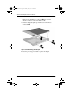
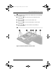
3. Remove the following screws:
❏
Three TM2.5 × 7.0 screws from the front edge of the base
enclosure
1
(Figure 5-21)
❏
Two TM2.5 × 5.0 screws from the hard drive bay
2
❏
Two TM2.5 × 5.0 screws from the Media Bay
3
❏
Evo Notebook N600c models—Two TM2.5 × 5.0
screws from the rear panel
4
, or
❏
Evo Notebook N610c models—Two TM2.5 × 7.0
screws from the rear panel
4
Figure 5-21. Removing the Top Cover Screws
279362-001.book!!Page!34!!Monday,!July!8,!2002!!11:49!AM