
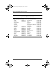
Specifications


5–14 Maintenance and Service Guide
Removal and Replacement Procedures
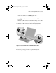
6. Disconnect the modem cable from the mini PCI
communications board
1
(Figure 5-8).
7. Spread the retaining tabs
2
to release the mini
PCI communications board. The board tilts up at a
45-degree angle.
8. Remove the board by pulling it away from the connector
at a 45-degree angle
3
.
Figure 5-8. Removing the Mini PCI Communications Board
Reverse the preceding procedure to install the mini PCI
communications board and mini PCI compartment cover.
279362-001.book!!Page!14!!Monday,!July!8,!2002!!11:49!AM