279362-001.book Page i Monday, July 8, 2002 11:49 AM b Maintenance and Service Guide Compaq Evo N610c and Evo N600c Document Part Number: 279362-001 July 2002 This guide is a troubleshooting reference used for maintaining and servicing the notebook. It provides comprehensive information on identifying notebook features, components, and spare parts, troubleshooting problems, and performing disassembly procedures.
79362-001.book Page ii Monday, July 8, 2002 11:49 AM © 2002 Compaq Information Technologies, L.P. Compaq, Evo, the Compaq logo, and Premier•Sound are trademarks of Compaq Information Technologies Group, L.P. In U.S. and/or other countries. Microsoft and Windows are trademarks of Microsoft Corporation. In U.S. and/or other countries. Intel and Pentium are trademarks of Intel Corporation in U.S. and/or other countries. All other product names mentioned herein may be trademarks of their respective companies.
279362-001.book Page iii Monday, July 8, 2002 11:49 AM Contents 1 Product Description 1.1 Models . . . . . . . . . . . . . . . . . . . . . . . . . . . . . . . . . . . . 1–2 1.2 Features . . . . . . . . . . . . . . . . . . . . . . . . . . . . . . . . . . . 1–9 1.3 Clearing a Password. . . . . . . . . . . . . . . . . . . . . . . . . 1–10 1.4 Power Management . . . . . . . . . . . . . . . . . . . . . . . . . 1–11 1.5 Notebook External Components . . . . . . . . . . . . . . . 1–12 1.6 Design Overview . . . . .
279362-001.book Page iv Monday, July 8, 2002 11:49 AM Contents 3 Illustrated Parts Catalog 3.1 Serial Number Location . . . . . . . . . . . . . . . . . . . . . . . 3–1 3.2 Notebook System Major Components . . . . . . . . . . . . 3–2 3.3 Miscellaneous Plastics Kit Components . . . . . . . . . 3–14 3.4 Mass Storage Devices . . . . . . . . . . . . . . . . . . . . . . . 3–16 3.5 Miscellaneous. . . . . . . . . . . . . . . . . . . . . . . . . . . . . . 3–20 4 Removal and Replacement Preliminaries 4.
279362-001.book Page v Monday, July 8, 2002 11:49 AM Contents 5.10 Switch Cover . . . . . . . . . . . . . . . . . . . . . . . . . . . . . 5.11 Display . . . . . . . . . . . . . . . . . . . . . . . . . . . . . . . . . . 5.12 Top Cover. . . . . . . . . . . . . . . . . . . . . . . . . . . . . . . . 5.13 System Board . . . . . . . . . . . . . . . . . . . . . . . . . . . . . 5.14 Fan . . . . . . . . . . . . . . . . . . . . . . . . . . . . . . . . . . . . . 5.15 Heat Sink . . . . . . . . . . . . . . . . . . . .
279362-001.book Page 1 Monday, July 8, 2002 11:49 AM 1 Product Description The Compaq Evo Notebook N610c and N600c Series offer advanced modularity, Mobile Intel Pentium 4 and Pentium III processors with 64-bit architecture, industry-leading Accelerated Graphics Port (AGP) implementation, and extensive multimedia support. Figure 1-1.
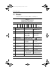
279362-001.book Page 2 Monday, July 8, 2002 11:49 AM Product Description 1.1 Models Computer models are shown in Tables 1-1 through 1-3. Table 1-1 Compaq Evo Notebook N610c Model Naming Conventions Key N610 P4 200 P4 40 V C 25 O XXXXXX-XXX 1 2 3 4 5 6 7 8 9 10 Key Description Options 1 Brand/Series designator N=Notebook 610=610c series 600=600c series 2 Processor type P4=Pentium 4 P3=Pentium III 3 Processor speed 200=2.0 Ghz 190=1.9 GHz 180=1.8 GHz 170=1.7 GHz 160=1.
279362-001.book Page 3 Monday, July 8, 2002 11:49 AM Product Description Table 1-2 Compaq Evo Notebook N610c Models The following Evo Notebook N610c models use config. code KT81 and feature: ■ Dual Stick pointing device (TouchPad and pointing stick) ■ 8-cell, 4.
279362-001.
279362-001.
279362-001.
279362-001.book Page 7 Monday, July 8, 2002 11:49 AM Product Description Table 1-3 Compaq Evo Notebook N600c Models The following Evo Notebook N600c models use config. code KBSZ and feature: ■ Dual Stick pointing device (TouchPad and pointing stick) ■ 8-cell, 4.
279362-001.
279362-001.book Page 9 Monday, July 8, 2002 11:49 AM Product Description 1.2 Features ■ The following processors are available, varying by notebook model: ❏ The Evo Notebook N610c features a Mobile Intel Pentium 4 2.0-, 1.9-, 1.8-, 1.7-, or 1.6-GHz processor, with 512-KB integrated L2 cache. ❏ The Evo Notebook N600c features a Mobile Intel Pentium III 1.066 GHz-M or 866-MHz-M processor, with 512-KB integrated L2 cache.
279362-001.
279362-001.book Page 11 Monday, July 8, 2002 11:49 AM Product Description 2. Remove the RTC battery (refer to Section 5.6, “Disk Cell RTC Battery”). 3. Wait approximately five minutes. 4. Replace the RTC battery and reassemble the notebook. 5. Connect AC power to the notebook. Do not reinsert any battery packs at this time. 6. Turn on the notebook. All passwords and all CMOS settings have been cleared. 1.
279362-001.book Page 12 Monday, July 8, 2002 11:49 AM Product Description 1.5 Notebook External Components The external components on the front and right side of the Evo Notebook N610c and Evo Notebook N600c are shown in Figure 1-2 and described in Table 1-4. . Figure 1-2. Front and Right Side Components Table 1-4 Front and Right Side Panel Components Item Component Function 1 Power light On: Power is turned on. Blinking: Notebook is in Standby.
279362-001.book Page 13 Monday, July 8, 2002 11:49 AM Product Description Table 1-4 Front and Right Side Panel Components (Continued) Item Component Function 3 Drive activity light Turns on when the hard drive, CD-, or DVD-ROM drive is accessed. 4 Media Bay light Turns on when the diskette drive in the Media Bay or the optional external diskette drive is accessed. 5 Infrared port Links to another IrDA-compliant device for wireless communication.
279362-001.book Page 14 Monday, July 8, 2002 11:49 AM Product Description The Evo Notebook N610c right side and rear panel components are shown in Figure 1-3 and described in Table 1-5. Figure 1-3.
279362-001.book Page 15 Monday, July 8, 2002 11:49 AM Product Description Table 1-5 Right Side and Rear Panel Components (Continued) Item Component Function 3 Parallel connector Connects a parallel device. 4 USB connectors (2) Connect USB devices. 5 RJ-45 jack (network models only) Connects the network cable. A network cable is not included with the notebook. 6 Serial connector Connects a serial device. 7 External monitor connector Connects an external monitor or overhead projector.
279362-001.book Page 16 Monday, July 8, 2002 11:49 AM Product Description The Evo Notebook N600c right side and rear panel components are shown in Figure 1-4 and described in Table 1-6. Figure 1-4. Right Side and Rear Panel Components— Evo Notebook N600c Table 1-6 Right Side and Rear Panel Components Item Component Function 1 MultiPort Connects wireless communication devices, such as an optional Bluetooth or 802.11b MultiPort module, and other options.
279362-001.book Page 17 Monday, July 8, 2002 11:49 AM Product Description Table 1-6 Right Side and Rear Panel Components (Continued) Item Component Function 3 Keyboard/mouse connector Connects an external keyboard or PS/2-compatible external mouse. To connect a keyboard and a mouse at the same time, use an optional Y-adapter. 4 Parallel connector Connects a parallel device. 5 Docking connector Connects the computer to the optional expansion base, convenience base, or port replicator.
279362-001.book Page 18 Monday, July 8, 2002 11:49 AM Product Description The keyboard components of the Evo Notebook N610c and Evo Notebook N600c are shown in Figure 1-5 and described in Table 1-7. Figure 1-5. Keyboard Components Table 1-7 Keyboard Components Item Component Function 1 F1 through F12 function keys Perform preset functions. 2 Embedded numeric keypad Converts keys to a numeric keypad. 3 Cursor control keys Move the cursor around the screen.
279362-001.book Page 19 Monday, July 8, 2002 11:49 AM Product Description The components on the top of the Evo Notebook N610c and Evo Notebook N600c are shown in Figure 1-6 and described in Table 1-8. Figure 1-6. Top Components Table 1-8 Top Components Item Component Function 1 Num lock light On: Num lock is on and the embedded numeric keypad is enabled. 2 Scroll lock light On: Scroll is on.
279362-001.book Page 20 Monday, July 8, 2002 11:49 AM Product Description Table 1-8 Top Components (Continued) Item Component Function 3 Caps lock light On: Caps lock is on. 4 Standby button Turns on the notebook if it is off. Initiates and exits Standby. When pressed with the Fn key, initiates Hibernation. 5 Stereo speakers (2) Produce stereo sound. 6 Easy Access buttons (4) Provide quick access to the Internet.
279362-001.book Page 21 Monday, July 8, 2002 11:49 AM Product Description The Evo Notebook N610c bottom components are shown in Figure 1-7 and described in Table 1-9. Figure 1-7. Bottom Components—Evo Notebook N610c Table 1-9 Bottom Components Item Component Function 1 Media Bay Accepts a diskette drive, CD- or DVD-ROM drive, or secondary battery pack. 2 Media Bay release latch Releases the Media Bay device from the connector.
9362-001.book Page 22 Monday, July 8, 2002 11:49 AM Product Description Table 1-9 Bottom Components (Continued) Item Component Function 3 Serial number Identifies the notebook; needed when you call Compaq customer support. 4 Docking connector Connects the notebook to the optional expansion base, convenience base, or port replicator. 5 Air vents (2) Allow airflow to cool internal components. 6 Fan Provides airflow to cool internal components.
279362-001.book Page 23 Monday, July 8, 2002 11:49 AM Product Description The Evo Notebook N600c bottom components are shown in Figure 1-8 and described in Table 1-10. Figure 1-8. Bottom Components—Evo Notebook N600c Table 1-10 Bottom Components Item Component Function 1 Media Bay Accepts a diskette drive, optical drive, or secondary battery pack. 2 Media Bay release latch Releases the Media Bay device from the connector. 3 Vent Allows airflow to cool internal components.
279362-001.book Page 24 Monday, July 8, 2002 11:49 AM Product Description Table 1-10 Bottom Components (Continued) Item Component Function 4 Fan Provides airflow to cool internal components. 5 Certificate of Authenticity label Contains the Product Key, which may need to be entered before using some Windows operating systems. 6 Hard drive security screw Secures the hard drive.
279362-001.book Page 25 Monday, July 8, 2002 11:49 AM Product Description 1.6 Design Overview This section presents a design overview of key parts and features of the notebook. Refer to Chapter 3, “Illustrated Parts Catalog,” to identify replacement parts, and Chapter 5, “Removal and Replacement Procedures,” for disassembly steps.
279362-001.book Page 1 Monday, July 8, 2002 11:49 AM 2 Troubleshooting Å WARNING: Only authorized technicians trained by Compaq should repair this equipment. All troubleshooting and repair procedures are detailed to allow only subassembly/module level repair. Because of the complexity of the individual boards and subassemblies, no one should attempt to make repairs at the component level or make modifications to any printed wiring board. Improper repairs can create a safety hazard.
279362-001.book Page 2 Monday, July 8, 2002 11:49 AM Troubleshooting ■ Compaq Diagnostics—A system information and diagnostic utility that is used within your Windows operating system. Use this utility whenever possible to: ❏ Display system information. ❏ Test system components. ❏ Troubleshoot a device configuration problem in Windows 2000, Windows XP Professional, or Windows XP Home.
279362-001.book Page 3 Monday, July 8, 2002 11:49 AM Troubleshooting Selecting from the File Menu Table 2-1 File Menu Select To Do This System Information ■ View identification information about the computer, a docking base, and any battery packs in the system. ■ View specification information about the processor, memory and cache size, and system ROM. Save to Floppy Save system configuration settings to a diskette. Restore from Floppy Restore system configuration settings from a diskette.
279362-001.book Page 4 Monday, July 8, 2002 11:49 AM Troubleshooting Selecting from the Security Menu Table 2-2 Security Menu Select To Do This Setup Password Enter, change, or delete a setup password. (The setup password is called an administrator password in Compaq Computer Security, a program accessed from the Windows Control Panel.) Power-on Password Enter, change, or delete a power-on password. DriveLock Passwords Enable/disable DriveLock; change a DriveLock User or Master password.
279362-001.book Page 5 Monday, July 8, 2002 11:49 AM Troubleshooting Selecting from the Advanced Menu Table 2-3 Advanced Menu Select To Do This Language (or press F2) Change the Computer Setup language. Boot Options Enable/disable: Device Options ■ QuickBoot, which starts the computer more quickly by eliminating some startup tests. (If you suspect a memory failure and want to test memory automatically during startup, disable QuickBoot.
279362-001.book Page 6 Monday, July 8, 2002 11:49 AM Troubleshooting Table 2-3 Advanced Menu (Continued) Select To Do This Device Options (continued) ■ Change the parallel port mode from Enhanced Parallel Port (EPP, the default setting) to standard, bidirectional, EPP or Enhanced Capabilities Port (ECP). ■ Set video-out mode to NTSC (default), PAL, NTSC-J, or PAL-M.* ■ Enable/disable all settings in the SpeedStep window. (When Disable is selected, the computer runs in Battery Optimized mode.
279362-001.book Page 7 Monday, July 8, 2002 11:49 AM Troubleshooting 2.2 Using Compaq Diagnostics When you access Compaq Diagnostics, a scan of all system components is displayed on the screen before the Compaq Diagnostics window opens. You can display more or less information from anywhere within Compaq Diagnostics by selecting Level on the menu bar. Compaq Diagnostics is designed to test Compaq components. If non-Compaq components are tested, the results may be inconclusive.
279362-001.book Page 8 Monday, July 8, 2002 11:49 AM Troubleshooting Obtaining, Saving, or Printing Diagnostic Test Information 1. Access Compaq Diagnostics by selecting Start > Settings > Control Panel > Compaq Diagnostics. 2. Select the Test tab. 3. In the scroll box, select the category or device you want to test. 4. Select a test type: 2–8 ❏ Quick Test—Runs a quick, general test on each device in a selected category. ❏ Complete Test—Performs maximum testing on each device in a selected category.
279362-001.book Page 9 Monday, July 8, 2002 11:49 AM Troubleshooting 5. Select a test mode: ❏ Interactive Mode—Provides maximum control over the testing process. You determine whether the test was passed or failed, and you may be prompted to insert or remove devices. ❏ Unattended Mode—Does not display prompts. If errors are found, they are displayed when testing is complete. 6. Click Begin Testing. 7.
279362-001.book Page 10 Monday, July 8, 2002 11:49 AM Troubleshooting 2.3 Troubleshooting Flowcharts Table 2-4 Troubleshooting Flowcharts Overview Flowchart Description 2.1 Initial Troubleshooting 2.2 No Power, Part 1 2.3 No Power, Part 2 2.4 No Power, Part 3 2.5 No Power, Part 4 2.6 No Video, Part 1 2.7 No Video, Part 2 2.8 Nonfunctioning Docking Station 2.9 No Operating System (Os) Loading 2.10 No Os Loading From Hard Drive, Part 1 2.11 No Os Loading From Hard Drive, Part 2 2.
279362-001.book Page 11 Monday, July 8, 2002 11:49 AM Troubleshooting Flowchart 2.1 - Initial Troubleshooting Begin troubleshooting. N Go to Flowchart 2.2, No Power, Part 1. Is there power? Y N Check LED board, speaker connections. Beeps, LEDs, or error messages? N Y Go to Flowchart 2.17, Nonfunctioning Device. All drives working? N Y Go to Flowchart 2.6, No Video, Part 1. Is there video? (no boot) N Keyboard/ pointing device working? Y N Y Go to Flowchart 2.9, No OS Loading.
279362-001.book Page 12 Monday, July 8, 2002 11:49 AM Troubleshooting Flowchart 2.2 - No Power, Part 1 No power (power LED is off). Remove from docking station (if applicable). N N Power up on battery power? Go to Flowchart 2.3, No Power, Part 2. Power up on battery power? *Reset power. Y Y N N Power up on AC power? Power up on AC power? *Reset power. Y Go to Flowchart 2.4, No Power, Part 3. Y Y Power up in docking station? * On some models there is a separate reset button.
279362-001.book Page 13 Monday, July 8, 2002 11:49 AM Troubleshooting Flowchart 2.3 - No Power, Part 2 Continued from Flowchart 2.2, No Power, Part 1. Visually check for debris in battery socket and clean if necessary. Y Power on? Done N Check battery by recharging, moving it to another computer, or replacing it. N Replace power supply (if applicable). Power on? Y N Done Power on? Go to Flowchart 2.4, No Power, Part 3.
279362-001.book Page 14 Monday, July 8, 2002 11:49 AM Troubleshooting Flowchart 2.4 - No Power, Part 3 Continued from Flowchart 2.3, No Power, Part 2. Plug directly into AC outlet. Y Power LED on? Done N Reseat AC adapter in computer and at power source. Y Power on? Done N N Power outlet active? External Try different outlet. Y Internal or external AC adapter? N Internal Go to Flowchart 2.5, No Power, Part 4. Replace power cord. Power on? Y Y Power on? Replace external AC adapter.
279362-001.book Page 15 Monday, July 8, 2002 11:49 AM Troubleshooting Flowchart 2.5 - No Power, Part 4 Continued from Flowchart 2.4, No Power, Part 3. Open computer. Y Reseat loose components and boards and replace damaged items. Loose or damaged parts? N Close computer and retest. N Power on? Replace the following items (if applicable). Check computer operation after each replacement: 1. Internal DC-DC converter* 2. Internal AC adapter 3. Processor board* 4.
279362-001.book Page 16 Monday, July 8, 2002 11:49 AM Troubleshooting Flowchart 2.6 - No Video, Part 1 No video. Docking station Go to Flowchart 2.7, No Video, Part 2. Stand-alone or docking station? * To change from internal to external display, use the hotkey combination. Stand-alone Internal or external display*? Y Adjust brightness. Press lid switch to ensure operation. A Adjust brightness.
279362-001.book Page 17 Monday, July 8, 2002 11:49 AM Troubleshooting Flowchart 2.7 - No Video, Part 2 Continued from Flowchart 2.6, No Video, Part 1. Remove notebook from docking station, if connected. Adjust display brightness. Check brightness of external monitor. N Y Go to “A” in Flowchart 2.6, No Video, Part 1. Video OK? Y Video OK? Done N Check that notebook is properly seated in docking station, for bent pins on cable, and for monitor connection. Try another external monitor.
279362-001.book Page 18 Monday, July 8, 2002 11:49 AM Troubleshooting Flowchart 2.8 - Nonfunctioning Docking Station (if applicable) Nonfunctioning docking station. Reseat power cord in docking station and power outlet. Check voltage setting on docking station. Reinstall notebook into docking station. Y Reset monitor cable connector at docking station.
279362-001.book Page 19 Monday, July 8, 2002 11:49 AM Troubleshooting Flowchart 2.9 - No Operating System (OS) Loading No OS loading.* Reseat power cord in docking station and power outlet. * Before beginning troubleshooting, always check cable connections, cable ends, and drives for bent or damaged pins. No OS loading from hard drive, go to Flowchart 2.10, No OS Loading from Hard Drive, Part 1. No OS loading from diskette drive, go to Flowchart 2.13, No OS Loading from Diskette Drive.
279362-001.book Page 20 Monday, July 8, 2002 11:49 AM Troubleshooting Flowchart 2.10 - No OS Loading from Hard Drive, Part 1 OS not loading from hard drive. Y Nonsystem disk message? N Go to Flowchart 2.11, No OS Loading from Hard Drive, Part 2. Reseat external hard drive. Y OS loading? Done N N Boot from CD? N Y Boot from diskette? Check the setup utility for correct booting order. Y N Go to Flowchart 2.13, No OS Loading from Diskette Drive.
279362-001.book Page 21 Monday, July 8, 2002 11:49 AM Troubleshooting Flowchart 2.11 - No OS Loading from Hard Drive, Part 2 Continued from Flowchart 2.10, No OS Loading from Hard Drive, Part 1. Reseat hard drive. N 1. Replace hard drive. 2. Replace system board. CD or diskette in drive? Y Hard drive accessible? Y Done N Remove diskette and reboot. Run FDISK. Y Boot from hard drive? N Done N Create partition, then format hard drive to bootable C:\ prompt.
279362-001.book Page 22 Monday, July 8, 2002 11:49 AM Troubleshooting Flowchart 2.12 - No OS Loading from Hard Drive, Part 3 Continued from Flowchart 2.11, No OS Loading from Hard Drive, Part 2. N System files on hard drive? Install OS and reboot. Y Y Y Virus on hard drive? OS loading from hard drive? Clean virus. N Done N Y Run SCANDISK and check for bad sectors. Diagnostics on diskette? Replace hard drive. N N Can bad sectors be fixed? Run diagnostics and follow recommendations.
279362-001.book Page 23 Monday, July 8, 2002 11:49 AM Troubleshooting Flowchart 2.13 - No OS Loading from Diskette Drive Y OS not loading from diskette drive. Reseat diskette drive. OS loading? Done N Y N Bootable diskette in drive? Nonsystem disk message? N Install bootable diskette and reboot computer. Y N Check diskette for system files. Try different diskette. Go to Flowchart 2.17, Nonfunctioning Device.
279362-001.book Page 24 Monday, July 8, 2002 11:49 AM Troubleshooting Flowchart 2.14 - No OS Loading from CD- or DVD-ROM Drive Y No OS loading from CD- or DVD-ROM Drive. N Bootable disc in drive? Disc in drive? N Y Install bootable disc and reboot computer. Try another bootable disc. Install bootable disc. Y Boots from CD or DVD? Done N Y Reseat drive. Boots from CD or DVD? Done N N Booting from another device? Y Y Booting order correct? N Go to Flowchart 2.17, Nonfunctioning Device.
279362-001.book Page 25 Monday, July 8, 2002 11:49 AM Troubleshooting Flowchart 2.15 - No Audio, Part 1 Y Turn up audio internally or externally. No audio. Audio? Done N N Y Notebook in docking station (if applicable)? N Go to Flowchart 2.16, No Audio, Part 2. Internal audio? Undock Y Replace the following docking station components one at a time as applicable. Check after each change. Go to Flowchart 2.16, No Audio, Part 2. 1. Reseat docking station audio cable. 2. Replace audio cable. 3.
279362-001.book Page 26 Monday, July 8, 2002 11:49 AM Troubleshooting Flowchart 2.16 - No Audio, Part 2 Continued from Flowchart 2.15, No Audio, Part 1. N Audio driver in OS configured? Reload audio drivers. Y N Correct drivers for application? Load drivers and set configuration in OS. Y Connect to external speaker. N Audio? Y Replace audio board and speaker connections in notebook (if applicable). Y Audio? Done N 1. Replace internal speakers. 2. Replace audio board (if applicable). 3.
279362-001.book Page 27 Monday, July 8, 2002 11:49 AM Troubleshooting Flowchart 2.17 - Nonfunctioning Device Nonfunctioning device. Reseat device. Unplug the nonfunctioning device from the notebook and inspect cables and plugs for bent or broken pins or other damage. Y Any physical device detected? Fix or replace broken item. Possible bad hard drive. Replace drive. Go to Flowchart 2.9, No OS Loading. Clear CMOS. N Reattach device. Close notebook, plug in power, and reboot.
279362-001.book Page 28 Monday, July 8, 2002 11:49 AM Troubleshooting Flowchart 2.18 - Nonfunctioning Keyboard Keyboard not operating properly. Connect notebook to good external keyboard. N Replace system board. External device works? Y Reseat internal keyboard connector (if applicable). N Replace internal keyboard or cable. OK? Y Y OK? Done Done N Replace system board.
279362-001.book Page 29 Monday, July 8, 2002 11:49 AM Troubleshooting Flowchart 2.19 - Nonfunctioning Pointing Device Pointing device not operating properly. Connect notebook to good external pointing device. N External device works? Replace system board. Y Reseat internal pointing device connector (if applicable). N OK? Replace internal pointing device or cable. Y Y Done OK? Done N Replace system board.
279362-001.book Page 30 Monday, July 8, 2002 11:49 AM Troubleshooting Flowchart 2.20 - No Network or Modem Connection No network or modem connection. N Network or modem jack active? Replace jack or have jack activated. Y Y Connect to nondigital line. Digital line? N N NIC/modem configured in OS? Y Reload drivers and reconfigure. OK? Done N Y Disconnect all power from the notebook and open. Replace NIC/modem (if applicable). Y Reseat NIC/modem (if applicable).
279362-001.book Page 1 Monday, July 8, 2002 11:49 AM 3 Illustrated Parts Catalog This chapter provides an illustrated parts breakdown and a reference for spare part numbers and option part numbers. 3.1 Serial Number Location When ordering parts or requesting information, provide the notebook serial number and model number located on the bottom of the notebook (Figure 3-1). Figure 3-1.
279362-001.book Page 2 Monday, July 8, 2002 11:49 AM Illustrated Parts Catalog 3.2 Notebook System Major Components Figure 3-2.
279362-001.book Page 3 Monday, July 8, 2002 11:49 AM Illustrated Parts Catalog Table 3-1 Spare Parts: Notebook System Major Components Item Description 1 Displays Spare Part Number For use with Evo Notebook N610c models only: 14.1-inch, SXGA+, CTFT 14.1-inch, XGA, CTFT For use with Evo Notebook N600c models only: 14.1-inch, SXGA+, CTFT 14.
279362-001.
279362-001.
279362-001.
279362-001.
279362-001.
279362-001.
279362-001.
279362-001.book Page 11 Monday, July 8, 2002 11:49 AM Illustrated Parts Catalog Table 3-1 Spare Parts: Notebook System Major Components (Continued) Item Description 9 System boards For use with Evo Notebook N610c models only For use with Evo Notebook N600c models only: Mobile Intel Pentium III processor 1.
279362-001.
279362-001.
279362-001.book Page 14 Monday, July 8, 2002 11:49 AM Illustrated Parts Catalog 3.
279362-001.
279362-001.book Page 16 Monday, July 8, 2002 11:49 AM Illustrated Parts Catalog 3.4 Mass Storage Devices Figure 3-4.
279362-001.
279362-001.
279362-001.
279362-001.book Page 20 Monday, July 8, 2002 11:49 AM Illustrated Parts Catalog 3.
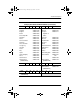
279362-001.book Page 21 Monday, July 8, 2002 11:49 AM Illustrated Parts Catalog Table 3-4 Spare Parts: Miscellaneous (not illustrated) (Continued) Spare Part Number Description Power cord, black, 6 feet 246959-011 246959-081 246959-021 246959-061 246959-291 246959-AD1 246959-AG1 234961-AA1 246959-031 246959-001 Australian Danish European/Middle Eastern/African Italian Japanese Korean Swiss Taiwanese U.K. English U.S.
279362-001.book Page 1 Monday, July 8, 2002 11:49 AM 4 Removal and Replacement Preliminaries This chapter provides essential information for proper and safe removal and replacement service. 4.1 Tools Required You will need the following tools to complete the removal and replacement procedures: ■ Magnetic screwdriver ■ Phillips P0 screwdriver ■ 7.0-mm socket wrench (for Evo Notebook N600c models) ■ Tool kit (includes connector removal tool, loopback plugs, and case utility tool) 4.
279362-001.book Page 2 Monday, July 8, 2002 11:49 AM Removal and Replacement Preliminaries Plastic Parts Using excessive force during disassembly and reassembly can damage plastic parts. Use care when handling the plastic parts. Apply pressure only at the points designated in the maintenance instructions. Cables and Connectors Cables must be handled with extreme care to avoid damage. Apply only the tension required to unseat or seat the cables during removal and insertion.
279362-001.book Page 3 Monday, July 8, 2002 11:49 AM Removal and Replacement Preliminaries 4.3 Preventing Damage to Removable Drives Removable drives are fragile components that must be handled with care. To prevent damage to the computer, damage to a removable drive, or loss of information, observe the following precautions: ■ Before removing or inserting a hard drive, shut down the computer. If you are unsure whether the computer is off or in Hibernation, turn the computer on, then shut it down.
279362-001.book Page 4 Monday, July 8, 2002 11:49 AM Removal and Replacement Preliminaries 4.4 Preventing Electrostatic Damage Many electronic components are sensitive to electrostatic discharge (ESD). Circuitry design and structure determine the degree of sensitivity. Networks built into many integrated circuits provide some protection, but in many cases the discharge contains enough power to alter device parameters or melt silicon junctions.
279362-001.book Page 5 Monday, July 8, 2002 11:49 AM Removal and Replacement Preliminaries ■ Store reusable electrostatic-sensitive parts from assemblies in protective packaging or nonconductive foam. ■ Use transporters and conveyers made of antistatic belts and roller bushings. Ensure that mechanized equipment used for moving materials is wired to ground and that proper materials are selected to avoid static charging. When grounding is not possible, use an ionizer to dissipate electric charges. 4.
279362-001.book Page 6 Monday, July 8, 2002 11:49 AM Removal and Replacement Preliminaries 4.7 Grounding Equipment and Methods Grounding equipment must include either a wrist strap or a foot strap at a grounded workstation. 4–6 ■ When seated, wear a wrist strap connected to a grounded system. Wrist straps are flexible straps with a minimum of one megohm ±10% resistance in the ground cords. To provide proper ground, wear a strap snugly against the skin at all times.
279362-001.
279362-001.book Page 8 Monday, July 8, 2002 11:49 AM Removal and Replacement Preliminaries Table 4-1 shows how humidity affects the electrostatic voltage levels generated by different activities.
279362-001.book Page 1 Monday, July 8, 2002 11:49 AM 5 Removal and Replacement Procedures This chapter provides removal and replacement procedures. Both Phillips P0 and Torx T8 screws are removed during disassembly. There are 37 screws and screwlocks, in seven different sizes, that must be removed and replaced when servicing the notebook. Make special note of each screw size and location during removal and replacement.
279362-001.book Page 2 Monday, July 8, 2002 11:49 AM Removal and Replacement Procedures 5.1 Serial Number Report the notebook serial number to Compaq when requesting information or ordering spare parts. The serial number is located on the bottom of the notebook (Figure 5-1). Figure 5-1. Serial Number Location 5.2 Disassembly Sequence Chart Use the chart below to determine the section number to be referenced when removing notebook components.
279362-001.book Page 3 Monday, July 8, 2002 11:49 AM Removal and Replacement Procedures Disassembly Sequence Chart (Continued) # of Screws Removed Section Description 5.3 Preparing the Notebook for Disassembly (Continued) Media Bay Device 0 Hard Drive 1 to remove hard drive 2 to remove hard drive bezel 5.4 Computer Feet 0 5.5 Mini PCI Communications Board 2 5.6 Disk Cell RTC Battery 0 5.7 Keyboard 1 5.8 Memory Expansion 0 5.9 TouchPad 0 5.10 Switch Cover 2 5.11 Display 3 5.
279362-001.book Page 4 Monday, July 8, 2002 11:49 AM Removal and Replacement Procedures 5.3 Preparing the Notebook for Disassembly Perform the following steps before disassembling the notebook: 1. Turn off the notebook. 2. Disconnect the AC adapter and all external devices. Battery Pack, 6-cell, Li ion Spare Part Number Information Battery packs, 6-cell, Li ion 232633-001 and 301952-001 3. Remove the battery pack by following these steps: a.
279362-001.book Page 5 Monday, July 8, 2002 11:49 AM Removal and Replacement Procedures b. Slide the battery release latch 1 toward the back of the notebook (Figure 5-2). c. Swing the right side of the battery pack up and to the left 2. d. Remove the battery pack 3. Figure 5-2. Removing the Battery Pack Reverse the preceding procedure to install the battery pack.
279362-001.
279362-001.book Page 7 Monday, July 8, 2002 11:49 AM Removal and Replacement Procedures 4. Remove a Media Bay device by following these steps: a. Turn the notebook bottom side up with the left side facing forward. b. Slide and hold the Media Bay release latch toward the back of the notebook 1 (Figure 5-3). c. Use the notch in the Media Bay device to slide the device out of the Media Bay 2. Figure 5-3. Removing a Media Bay Device Reverse the preceding procedure to install the Media Bay device.
279362-001.book Page 8 Monday, July 8, 2002 11:49 AM Removal and Replacement Procedures Hard Drive Spare Part Number Information For use with Evo Notebook N610c models only: 40 GB 30 GB 20 GB For use with Evo Notebook N600c models only: 30 GB 20 GB 15 GB 10 GB 265495-001 257660-001 235540-101 217096-001 235421-001 241429-001 217094-001 5. Remove the hard drive by following these steps: a. Turn the notebook bottom side up with the right side facing forward.
279362-001.book Page 9 Monday, July 8, 2002 11:49 AM Removal and Replacement Procedures b. Remove the PM2.5 × 2.5 hard drive retention screw 1 (Figure 5-4). c. Separate the hard drive bezel 2. d. Use the bezel to slide the hard drive forward 3 to unseat the hard drive connector from the system board. e. Remove the hard drive. Figure 5-4. Removing the Hard Drive Reverse the preceding procedure to install the hard drive.
279362-001.book Page 10 Monday, July 8, 2002 11:49 AM Removal and Replacement Procedures 6. Loosen the two PM1.5 × 3.5 screws 1 that secure the hard drive bezel to the hard drive (Figure 5-5). 7. Remove the hard drive bezel from the hard drive 2. Figure 5-5. Removing the Hard Drive Bezel hard drive bezel is included in the Miscellaneous Plastics Kit, ✎ The spare part number 241439-001.
279362-001.book Page 11 Monday, July 8, 2002 11:49 AM Removal and Replacement Procedures 5.4 Computer Feet The notebook feet are adhesive-backed rubber pads. The notebook feet are included in the Miscellaneous Plastics Kit (spare part number 241439-001). Refer to Figure 5-6 for notebook feet locations. Figure 5-6.
279362-001.book Page 12 Monday, July 8, 2002 11:49 AM Removal and Replacement Procedures 5.5 Mini PCI Communications Board Evo Notebook N600c models contain a memory ✎ Compaq expansion slot in this location. Refer to Section 5.8, steps 5 and 6, for instructions on removing a memory expansion board. The mini PCI compartment cover is included in the Miscellaneous Plastics Kit (spare part number 241439-001).
279362-001.book Page 13 Monday, July 8, 2002 11:49 AM Removal and Replacement Procedures 3. Remove the two PM2.5 × 5.0 screws 1 that secure the mini PCI compartment cover to the base enclosure (Figure 5-7). 4. Lift the left edge of the cover and swing it up and to the right 2. 5. Remove the cover. mini PCI compartment cover is included in the ✎ The Miscellaneous Plastics Kit (spare part number 241439-001). Figure 5-7.
279362-001.book Page 14 Monday, July 8, 2002 11:49 AM Removal and Replacement Procedures 6. Disconnect the modem cable from the mini PCI communications board 1 (Figure 5-8). 7. Spread the retaining tabs 2 to release the mini PCI communications board. The board tilts up at a 45-degree angle. 8. Remove the board by pulling it away from the connector at a 45-degree angle 3. Figure 5-8.
279362-001.book Page 15 Monday, July 8, 2002 11:49 AM Removal and Replacement Procedures 5.6 Disk Cell RTC Battery disk cell real time clock (RTC) battery on the Compaq Evo ✎ The Notebook N600c model is located under the memory expansion slot compartment cover. Refer to Section 5.8 for instructions on removing the memory expansion slot cover. The procedures used to remove an RTC battery are the same for the Evo notebook N610c and Evo Notebook N600c.
279362-001.book Page 16 Monday, July 8, 2002 11:49 AM Removal and Replacement Procedures 3. Use a flat blade tool to remove the battery 1 from the socket on the system board (Figure 5-9). system ROM 2 is also accessible when the mini PCI ✎ The compartment cover is removed. Figure 5-9. Removing the Disk Cell RTC Battery notebook uses a CR1220 lithium disk cell battery. When ✎ The replacing the RTC battery, insert the battery with the “+” sign facing up.
279362-001.book Page 17 Monday, July 8, 2002 11:49 AM Removal and Replacement Procedures 5.
279362-001.
279362-001.book Page 19 Monday, July 8, 2002 11:49 AM Removal and Replacement Procedures 1. Prepare the notebook for disassembly (Section 5.3). 2. Turn the notebook bottom side up with the front facing you. 3. Remove the TM2.5 × 7.0 screw that secures the keyboard to the base enclosure (Figure 5-10). Figure 5-10. Removing the Keyboard Screw 4. Turn the notebook top side up with the front facing you. 5. Open the notebook.
279362-001.book Page 20 Monday, July 8, 2002 11:49 AM Removal and Replacement Procedures 6. Slide the four tabs on the top of the keyboard forward (Figure 5-11). Figure 5-11.
279362-001.book Page 21 Monday, July 8, 2002 11:49 AM Removal and Replacement Procedures 7. Lift the top edge of the keyboard and swing it up and forward until it rests on the top cover 1 (Figure 5-12). 8. Disengage the keyboard cable from the retaining clips in the top cover. 9. Release the ZIF connector to which the pointing device cable is attached 2 and disconnect the pointing device cable 3. 10. Release the ZIF connector to which the keyboard cable is attached 4 and disconnect the keyboard cable 5.
279362-001.book Page 22 Monday, July 8, 2002 11:49 AM Removal and Replacement Procedures 5.8 Memory Expansion Evo Notebook N600c models contain the mini PCI ✎ Compaq communications board slot in this location. Refer to Section 5.5, steps 6 through 8, for instructions on removing a mini PCI communications board. The memory expansion compartment cover is included in the Miscellaneous Plastics Kit (spare part number 241439-001).
279362-001.book Page 23 Monday, July 8, 2002 11:49 AM Removal and Replacement Procedures 1. Prepare the notebook for disassembly (Section 5.3). 2. Remove the keyboard (Section 5.7). 3. Lift the left side of the memory expansion compartment cover 1 and swing the cover forward 2 (Figure 5-13). 4. Remove the memory expansion compartment cover. Figure 5-13.
279362-001.book Page 24 Monday, July 8, 2002 11:49 AM Removal and Replacement Procedures 5. Spread the retaining tabs 1 that secure the memory expansion board to the socket. The board rises up at a 45-degree angle (Figure 5-14). 6. Pull the board away from the socket at a 45-degree angle 2. Figure 5-14. Removing a Memory Expansion Board Reverse the preceding procedure to replace a memory expansion board.
279362-001.book Page 25 Monday, July 8, 2002 11:49 AM Removal and Replacement Procedures 5.
279362-001.book Page 26 Monday, July 8, 2002 11:49 AM Removal and Replacement Procedures 4. Lift up on the left side of the TouchPad 1 until it disengages from the top cover (Figure 5-15). 5. Swing the TouchPad up and back 2 and rest it on the top cover. 6. Disconnect the TouchPad cables 3 and 4 from the system board. Figure 5-15. Removing the TouchPad 7. Remove the TouchPad. Reverse the preceding procedure to replace the TouchPad.
279362-001.book Page 27 Monday, July 8, 2002 11:49 AM Removal and Replacement Procedures 5.10 Switch Cover Switch Cover Spare Part Number Information Switch cover 241438-001 1. Prepare the notebook for disassembly (Section 5.3). 2. Remove the keyboard (Section 5.7). 3. Position the notebook so the rear panel faces you. 4. Remove the two black TM2.5 × 7.0 screws that secure the switch cover to the base enclosure (Figure 5-16). Figure 5-16.
279362-001.book Page 28 Monday, July 8, 2002 11:49 AM Removal and Replacement Procedures 5. Position the notebook so the front faces you. 6. Open the notebook as far as it will open. 7. Lift the switch cover up 1, slide it forward 2, and rest it on the top cover (Figure 5-17). 8. Disconnect the left 3 and right speaker cables 4 from the system board. Figure 5-17. Removing the Switch Cover 9. Remove the switch cover. Reverse the preceding procedure to replace the switch cover.
279362-001.book Page 29 Monday, July 8, 2002 11:49 AM Removal and Replacement Procedures 5.11 Display Display Spare Part Number Information For use with Evo Notebook N610c models only: 14.1-inch, SXGA+, CTFT 14.1-inch, XGA, CTFT For use with Evo Notebook N600c models only: 14.1-inch, SXGA+, CTFT 14.1-inch, XGA, CTFT 291261-001 291262-001 241433-001 241434-001 1. Prepare the notebook for disassembly (Section 5.3). 2. Remove the keyboard (Section 5.7). 3. Remove the switch cover (Section 5.10). 4.
279362-001.book Page 30 Monday, July 8, 2002 11:49 AM Removal and Replacement Procedures 5. Remove the TM2.5 × 7.0 screw that secures the display ground cable to the top cover 1 (Figure 5-18). procedure described below for disconnecting the display ✎ The video cable 2 applies only to Evo Notebook N610c models. The procedure for disconnecting the display video cable on Evo Notebook N600c models is described on the following page. 6.
279362-001.book Page 31 Monday, July 8, 2002 11:49 AM Removal and Replacement Procedures display video cable on Compaq Evo Notebook N600c ✎ The models is located on the left side of the system board. Refer to Figure 5-19 for information on disconnecting the display video cable on Evo Notebook N600c models. Figure 5-19. Disconnecting the Display Video Cable on an Evo Notebook N600c 7. Partially close the notebook. 8. Position the notebook so the rear panel faces you.
279362-001.book Page 32 Monday, July 8, 2002 11:49 AM Removal and Replacement Procedures 9. Remove the two TM2.5 × 7.0 screws 1 that secure the display to the base enclosure (Figure 5-20). 10. Lift the display straight up and remove it from the base enclosure 2. Figure 5-20. Removing the Display Reverse the preceding procedure to replace the display.
279362-001.book Page 33 Monday, July 8, 2002 11:49 AM Removal and Replacement Procedures 5.12 Top Cover Top Cover Spare Part Number Information For use with Evo Notebook N610c models only For use with Evo Notebook N600c models only 291264-001 241436-001 1. Prepare the notebook for disassembly (Section 5.3) and remove the following components: a. Keyboard (Section 5.7) b. Memory expansion compartment cover (Section 5.8) c. Switch cover (Section 5.10) d. Display (Section 5.11) 2.
279362-001.book Page 34 Monday, July 8, 2002 11:49 AM Removal and Replacement Procedures 3. Remove the following screws: ❏ Three TM2.5 × 7.0 screws from the front edge of the base enclosure 1 (Figure 5-21) ❏ Two TM2.5 × 5.0 screws from the hard drive bay 2 ❏ Two TM2.5 × 5.0 screws from the Media Bay 3 ❏ Evo Notebook N600c models—Two TM2.5 × 5.0 screws from the rear panel 4, or ❏ Evo Notebook N610c models—Two TM2.5 × 7.0 screws from the rear panel 4 Figure 5-21.
279362-001.book Page 35 Monday, July 8, 2002 11:49 AM Removal and Replacement Procedures 4. Turn the notebook top side up with the rear panel facing you. 5. For Evo Notebook N610c models only—Remove the PM2.0 × 4.0 1 and TM2.5 × 7.0 2 screws that secure the top cover to the base enclosure (Figure 5-22). 6. Insert a flat blade screwdriver into the slot 3 on the rear edge of the top cover to disengage the cover from the I/O bracket. 7. Lift the top cover straight up and remove it from the base enclosure 4.
279362-001.book Page 36 Monday, July 8, 2002 11:49 AM Removal and Replacement Procedures 5.13 System Board System Board Spare Part Number Information For use with Evo Notebook N610c models only For use with Evo Notebook N600c models only: Mobile Intel Pentium III processor 1.
279362-001.book Page 37 Monday, July 8, 2002 11:49 AM Removal and Replacement Procedures ✎ Steps 3 through 5 apply only to Evo Notebook N600c models. 3. Remove the tape that secures the modem cable to the system board 1 (Figure 5-23). 4. Remove the two 7.0-mm bushing guides 2 on either side of the docking connector that secure the system board to the base enclosure. 5. Remove the three TM2.5 × 5.0 screws 3 that secure the system board to the base enclosure. Figure 5-23.
279362-001.book Page 38 Monday, July 8, 2002 11:49 AM Removal and Replacement Procedures ✎ Steps 6 and 7 apply only to Evo Notebook N610c models. 6. Remove the two TM2.5 × 5.0 screws 1 that secure the system board to the base enclosure through the rear panel (Figure 5-24). 7. Remove the three TM2.5 × 5.0 screws 2 that secure the top cover to the base enclosure. Figure 5-24.
279362-001.book Page 39 Monday, July 8, 2002 11:49 AM Removal and Replacement Procedures removing the system board, do not remove the following ✎ When screws (Figure 5-25): ■ Four screws 1 that secure the processor bracket to the system board ■ Two screws 2 that secure the heat sink to the system board ■ Two screws 3 that secure the hard drive connector the system board ■ Four screws 4 that secure the PC Card assembly to the system board Figure 5-25.
279362-001.book Page 40 Monday, July 8, 2002 11:49 AM Removal and Replacement Procedures 8. Use the Media Bay connector 1 to lift the right side of the system board 2 until it rests at a 45-degree angle (Figure 5-26). 9. Slide the system board out of the base enclosure at a 45-degree angle 3. Figure 5-26.
279362-001.book Page 41 Monday, July 8, 2002 11:49 AM Removal and Replacement Procedures 5-28 applies only to Evo Notebook N600c models. When ✎ Figure handling the system board, be careful not to put stress on the I/O interface board 1. The narrow profile of this board makes it susceptible to being damaged when mishandled. Do not remove the screw 2 that secures the I/O interface board to the system board or attempt to remove the I/O interface board.
279362-001.book Page 42 Monday, July 8, 2002 11:49 AM Removal and Replacement Procedures 5-29 applies only to Evo Notebook N610c models. When ✎ Figure handling the system board, be careful not to put stress on the I/O interface board 1. The narrow profile of this board makes it susceptible to being damaged when mishandled. The I/O board should only be removed and handled using the Media Bay connector 2. Figure 5-29.
279362-001.book Page 43 Monday, July 8, 2002 11:49 AM Removal and Replacement Procedures 5.14 Fan Fan Spare Part Number Information For use with Evo Notebook N610c models only For use with Evo Notebook N600c models only 291266-001 255528-001 1. Prepare the notebook for disassembly (Section 5.3) and remove the following components: a. RTC battery (Section 5.6) b. Keyboard (Section 5.7) c. Memory expansion compartment cover (Section 5.8) d. TouchPad (Section 5.9) e. Switch cover (Section 5.10) f.
279362-001.book Page 44 Monday, July 8, 2002 11:49 AM Removal and Replacement Procedures 3. Disconnect the fan cable from the system board (Figure 5-30). Figure 5-30. Disconnecting the Fan Cable 4. Turn the system board top side up with the rear panel facing you.
279362-001.book Page 45 Monday, July 8, 2002 11:49 AM Removal and Replacement Procedures ✎ Steps 5 through 7 apply only to Evo Notebook N600c models. 5. Remove the PM2.0 × 4.0 screw 1 and PM2.5 × 5.0 screw 2 that secure the fan to the system board (Figure 5-31). 6. While holding the system board above the work surface, push the left side of the fan up 3 from the bottom of the system board. 7. When the left edge of the fan has cleared the system board, slide the fan to the left 4 and out of the heat sink.
279362-001.book Page 46 Monday, July 8, 2002 11:49 AM Removal and Replacement Procedures ✎ Steps 8 and 9 apply only to Evo Notebook N610c models. 8. Remove the three PM2.0 × 4.0 screws 1 that secure the fan to the heat sink (Figure 5-32). 9. Lift the fan out of the heat sink 2. Figure 5-32. Removing the Fan on an Evo Notebook N610c 10. Remove the fan. Reverse the preceding procedure to replace the fan.
279362-001.book Page 47 Monday, July 8, 2002 11:49 AM Removal and Replacement Procedures 5.15 Heat Sink ✎ This section applies only to Evo Notebook N610c models. Heat Sink Spare Part Number Information Heat sink 303103-001 1. Prepare the notebook for disassembly (Section 5.3) and remove the following components: a. RTC battery (Section 5.6) b. Keyboard (Section 5.7) c. Memory expansion compartment cover (Section 5.8) d. TouchPad (Section 5.9) e. Switch cover (Section 5.10) f. Display (Section 5.
279362-001.book Page 48 Monday, July 8, 2002 11:49 AM Removal and Replacement Procedures 2. Turn the system board bottom side up with the rear panel facing you. 3. Disconnect the fan cable from the system board (Figure 5-33). Figure 5-33.
279362-001.book Page 49 Monday, July 8, 2002 11:49 AM Removal and Replacement Procedures 4. Turn the system board top side up with the rear panel facing you. 5. Remove the six PM2.0 × 4.0 screws 1 that secure the processor mounting bracket and heat sink to the system board (Figure 5-34). 6. Remove the processor mounting bracket 2. Figure 5-34.
279362-001.book Page 50 Monday, July 8, 2002 11:49 AM Removal and Replacement Procedures 7. Lift the system board straight up 1. The heat sink 2 will remain resting on the work surface (Figure 5-35). Figure 5-35. Removing the Heat Sink Reverse the preceding procedure to replace the heat sink.
279362-001.book Page 51 Monday, July 8, 2002 11:49 AM Removal and Replacement Procedures 5.16 Processor ✎ This section applies only to Evo Notebook N610c models. Processor Spare Part Number Information Mobile Intel Pentium 4 2.0 GHz Mobile Intel Pentium 4 1.9 GHz Mobile Intel Pentium 4 1.8 GHz Mobile Intel Pentium 4 1.7 GHz Mobile Intel Pentium 4 1.6 GHz 303282-001 291580-001 291269-001 291268-001 291267-001 1. Prepare the notebook for disassembly (Section 5.3) and remove the following components: a.
279362-001.book Page 52 Monday, July 8, 2002 11:49 AM Removal and Replacement Procedures 3. Insert the tip of a flat-blade screwdriver into the slot on the processor locking screw. 4. Turn the screwdriver counterclockwise 1 to release the processor (Figure 5-36). 5. Remove the processor from the socket on the system board 2. installing the processor, make sure the gold triangle 3 is in ✎ When the lower right corner. Figure 5-36.
279362-001.book Page 53 Monday, July 8, 2002 11:49 AM Removal and Replacement Procedures 5.17 DC-DC Converter Board DC-DC Converter Board Spare Part Number Information For use with Evo Notebook N610c models only For use with Evo Notebook N600c models only 291263-001 241435-001 1. Prepare the notebook for disassembly (Section 5.3) and remove the following components: a. RTC battery (Section 5.6) b. Keyboard (Section 5.7) c. Memory expansion compartment cover (Section 5.8) d. TouchPad (Section 5.9) e.
279362-001.book Page 54 Monday, July 8, 2002 11:49 AM Removal and Replacement Procedures 3. Lift the left and right edges of the DC-DC converter board to disconnect the board from the system board (Figure 5-37). Figure 5-37. Removing the DC-DC Converter Board 4. Remove the DC-DC converter board. Reverse the preceding procedure to replace the DC-DC converter board.
279362-001.book Page 55 Monday, July 8, 2002 11:49 AM Removal and Replacement Procedures 5.18 Modem Cable modem cable is spared with the base enclosure. Modem ✎ The cables are also included in the Miscellaneous Plastics Kit (spare part number 241439-001). 1. Prepare the notebook for disassembly (Section 5.3) and remove the following components: a. RTC battery (Section 5.6) b. Keyboard (Section 5.7) c. Memory expansion compartment cover (Section 5.8) d. TouchPad (Section 5.9) e. Switch cover (Section 5.
279362-001.book Page 56 Monday, July 8, 2002 11:49 AM Removal and Replacement Procedures 3. Lift the modem connector out of the base enclosure 1 and disengage the modem cable 2 from the alignment clips and tabs in the base enclosure (Figure 5-38). Figure 5-38. Removing the Modem Cable 4. Remove the modem cable.
279362-001.book Page 57 Monday, July 8, 2002 11:49 AM Removal and Replacement Procedures installing the modem cable, route the cable along the path ✎ When indicated in Figure 5-39. Figure 5-39.
279362-001.book Page 1 Monday, July 8, 2002 11:49 AM 6 Specifications This chapter provides physical and performance specifications. Table 6-1 Notebook Dimensions Height Width Depth 3.1 cm 30.7 cm 25.0 cm 1.2 in 12.1 in 9.8 in 2.5 kg 5.5 lb 2.1 kg 4.
279362-001.book Page 2 Monday, July 8, 2002 11:49 AM Specifications Table 6-1 Notebook (Continued) Temperature Operating Nonoperating 10° C to 35° C -20° C to 60° C 50° F to 95° F -4° F to 140° F Relative humidity (noncondensing) Operating Nonoperating 10 to 90% 5 to 95%, 38.7° C/101.
279362-001.book Page 3 Monday, July 8, 2002 11:49 AM Specifications Table 6-2 14.1-inch XGA, TFT Display Dimensions Height Depth Width 21.40 cm 28.50 cm 35.81 cm Number of colors Up to 16.8 million Contrast ratio 150:1 Brightness 120 nits typical 8.46 in 11.22 in 14.10 in Pixel resolution Pitch Format Configuration 0.264 × 0.264 mm 1024 × 768 RGB vertical stripe Backlight Edge lit Character display 80 × 25 Refresh 60 Hz Total power consumption 4.
279362-001.book Page 4 Monday, July 8, 2002 11:49 AM Specifications Table 6-3 Hard Drives 40.0 GB 30.0 GB 20.0 GB 15.0 GB User capacity per drive1 40.0 30.0 GB 20.0 GB 15.0 GB Drive height 9.5 mm 9.5 mm 9.5 mm 9.5 mm Drive width 70.0 mm 70.0 mm 70.0 mm 70.0 mm Interface type ATA-5 ATA-5 ATA-5 ATA-4 Seek times (typical read, including setting) Single track Average Full stroke User addressable sectors3 2.5 ms 12.0 ms 23.0 ms 2.5 ms 12.0 ms 23.0 ms 2.5 ms 12.0 ms 23.0 ms 2.
279362-001.book Page 5 Monday, July 8, 2002 11:49 AM Specifications Table 6-3 Hard Drives (Continued) 40.0 GB 30.0 GB 20.0 GB 15.0 GB 22,784 4 293 to 560 25,800 2 398 to 731 22,784 4 293 to 560 25,800 2 398 to 731 512 512 512 512 Buffer size 2 MB 512 KB 512 KB 512 KB Disk rotational speed 4200 rpm 4200 rpm 4200 rpm 4200 rpm 66.6 100 66.
279362-001.book Page 6 Monday, July 8, 2002 11:49 AM Specifications Table 6-4 Diskette Drive Diskette size 3.5 in Light On system Height 12.7 mm Bytes per sector 512 0.5 in Sectors per track High density Low density 18 (1.44 MB) 9 Tracks per side High density Low density 80 80 Read/write heads 2 15 (1.
279362-001.book Page 7 Monday, July 8, 2002 11:49 AM Specifications Table 6-5 CD-ROM Drive Applicable disc CD-ROM (Mode 1, 2, and 3) CD-XA ready (Mode 2, Form 1 and 2) CD-I ready (Mode 2, Form 1 and 2) CD-R (read only) CD Plus Photo CD (single/multisession) CD-Extra Video CD CD-WO (fixed packets only) CD-Bridge Center hole diameter 1.5 cm Disc diameter 12 cm, 8 cm Disc thickness 1.2 mm Track pitch 1.6 µm .
279362-001.book Page 8 Monday, July 8, 2002 11:49 AM Specifications Table 6-6 DVD-ROM Drive Applicable disc DVD-5, DVD-9, DVD-10 CD-ROM (Mode 1 and 2) CD Digital Audio CD-XA ready (Mode 2, Form 1 and 2) CD-I ready (Mode 2, Form 1 and 2) CD-R (read only) CD Plus Photo CD (single/multisession) CD-Bridge Center hole diameter 1.5 cm Disc diameter 12 cm, 8 cm Disc thickness 1.2 mm Track pitch .74 µm .59 in Access time Random Full stroke < 150 ms < 225 ms Audio output level Line-out, 0.
279362-001.book Page 9 Monday, July 8, 2002 11:49 AM Specifications Table 6-7 CD-RW Drive Center hole diameter .39 cm Disk diameter 12 cm, 8 cm Disk thickness .12 cm Track pitch .74 µm .59 in .47 in Access time Random Full stroke < 150 ms < 225 ms Audio output level Line-out, 0.7 Vrms Cache buffer 128 KB/s minimum Data transfer rate Sustained, 16X Sustained, 4X CD-RW Normal PIO Mode 4 (single burst) 150 KB/s 5,520 KB/s 16.
279362-001.book Page 10 Monday, July 8, 2002 11:49 AM Specifications Table 6-8 AC Adapter Dimensions Height Depth Width Weight 2.79 cm 3.61 cm 9.40 cm 1.10 in 1.42 in 3.70 in .18 kg .39 lb Power supply (input) Operating voltage Operating current Operating frequency range Maximum transient 90 to 260 VAC RMS nominal 1.3 A RMS 47 to 63 Hz nominal 4/50 kV Table 6-9 8-cell, Li ion Battery Pack Dimensions Length Width Depth Weight 125.80 cm 88.00 cm 20.40 cm 0.43 kg 4.95 in 3.46 in 0.80 in 0.
279362-001.book Page 11 Monday, July 8, 2002 11:49 AM Specifications Table 6-10 System DMA Hardware DMA System Function DMA0 Available for audio DMA1 Entertainment audio (default; alternate = DMA0, DMA3, none) DMA2 Diskette drive DMA3 ECP parallel port LPT1 (default; alternate = DMA0, none) DMA4 DMA controller cascading (not available) DMA5 Available for PC Card DMA6 Not assigned DMA7 Not assigned ✎ PC Card controller can use DMA 1, 2, or 5.
279362-001.
279362-001.book Page 13 Monday, July 8, 2002 11:49 AM Specifications Table 6-12 System I/O Addresses I/O Address (hex) System Function (shipping configuration) 000–00F DMA controller no. 1 010–01F Unused 020–021 Interrupt controller no.
279362-001.book Page 14 Monday, July 8, 2002 11:49 AM Specifications Table 6-12 System I/O Addresses (Continued) I/O Address (hex) System Function (shipping configuration) 0A2–0BF Unused 0C0–0DF DMA controller no.
279362-001.
279362-001.
279362-001.
279362-001.
279362-001.
279362-001.
279362-001.
279362-001.
279362-001.book Page 7 Monday, July 8, 2002 11:49 AM Connector Pin Assignments Table A-10 Docking (Continued) 30 60 90 120 1 31 61 91 Pin Signal Pin Signal 31 AUGND 46 SRDY 32 XA0/L OUT 47 EBOXS1/GND 33 XSD/MIC SN 48 RI1 EX 34 XA1/R OUT 49 GND 35 GND 50 SLCT LD0 36 GND 51 PE LD1 37 EXPCLK2 52 ACK LD2 38 +3.
279362-001.
279362-001.
279362-001.book Page 1 Monday, July 8, 2002 11:49 AM B Power Cord Set Requirements 3-Conductor Power Cord Set The wide range input feature of the notebook permits it to operate from any line voltage from 100 to 120 or 220 to 240 volts AC. The power cord set received with the notebook meets the requirements for use in the country where the equipment is purchased. Power cord sets for use in other countries must meet the requirements of the country where the notebook is used.
279362-001.
279362-001.book Page 3 Monday, July 8, 2002 11:49 AM Power Cord Set Requirements 3-Conductor Power Cord Set Requirements Country Accredited Agency Applicable Note Number United Kingdom BSI 1 United States UL 2 Notes 1. The flexible cord must be Type HO5VV-F, 3-conductor, 1.0 mm2 conductor size. The power cord set fittings (appliance coupler and wall plug) must bear the certification mark of the agency responsible for evaluation in the country where it will be used. 2.
279362-001.book Page 1 Monday, July 8, 2002 11:49 AM C Screw Listing This appendix provides specification and reference information for the screws used in the notebook. All screws listed in this appendix are available in the Miscellaneous Screw Kit, spare part number 241440-001.
279362-001.book Page 2 Monday, July 8, 2002 11:49 AM Table C-1 Phillips Metric 2.5 × 2.5 Screw Color Qty Length Thread Head Width Black 1 2.5 mm 2.5 mm 5.0 mm Where used: One screw that secures the hard drive to the base enclosure (documented in Section 5.3) Figure C-1. PM2.5 × 2.
279362-001.book Page 3 Monday, July 8, 2002 11:49 AM Table C-2 Phillips Metric 1.5 × 3.5 Screw Color Qty Length Thread Head Width Black 2 1.5 mm 3.5 mm 3.0 mm Where used: Two screws that secure the hard drive bezel to the hard drive (documented in Section 5.3) Figure C-2. PM1.5 × 3.
279362-001.book Page 4 Monday, July 8, 2002 11:49 AM Table C-3 Phillips Metric 2.5 × 5.0 Screw Color Qty Length Thread Head Width Black 3 5.0 mm 2.5 mm 4.5 mm Where used: Evo Notebook N600c models—Two screws that secure the memory expansion compartment cover to the base enclosure Evo Notebook N610c models—Two screws that secure the mini PCI compartment cover to the base enclosure (documented in Section 5.5) Figure C-3. PM2.5 × 5.
279362-001.book Page 5 Monday, July 8, 2002 11:49 AM Table C-3 Phillips Metric 2.5 × 5.0 Screw (Continued) Color Qty Length Thread Head Width Black 3 5.0 mm 2.5 mm 4.5 mm Where used: Evo Notebook N610c models—One screw that secures the fan to the heat sink (documented in Section 5.14) Figure C-4. PM2.5 × 5.
279362-001.book Page 6 Monday, July 8, 2002 11:49 AM Table C-4 Torx T8 Metric 2.5 × 7.0 Screw Color Qty Length Thread Head Width Black 12 7.0 mm 2.5 mm 5.0 mm Where used: 1 One screw that secures the keyboard to the base enclosure (documented in Section 5.7) 2 Three screws that secure the top cover to the base enclosure (documented in Section 5.12) Figure C-5. TM2.5 × 7.
279362-001.book Page 7 Monday, July 8, 2002 11:49 AM Table C-4 Torx T8 Metric 2.5 × 7.0 Screw (Continued) Color Qty Length Thread Head Width Black 12 7.0 mm 2.5 mm 5.0 mm Where used: 1 Two screws that secure the switch cover to the base enclosure (documented in Section 5.10) 2 Two screws that secure the display to the base enclosure (documented in Section 5.11) 3 Evo Notebook N610c models—Two screws that secure the top cover to the base enclosure (documented in Section 5.12) Figure C-6. TM2.
279362-001.book Page 8 Monday, July 8, 2002 11:49 AM Table C-4 Torx T8 Metric 2.5 × 7.0 Screw (Continued) Color Qty Length Thread Head Width Black 12 7.0 mm 2.5 mm 5.0 mm Where used: 1 One screw that secures the display ground cable to the base enclosure (documented in Section 5.11) 2 Evo Notebook N610c models—One screw that secures the top cover to the base enclosure (documented in Section 5.12) Figure C-7. TM2.5 × 7.
279362-001.book Page 9 Monday, July 8, 2002 11:49 AM Table C-5 Torx T8 Metric 2.5 × 5.0 Screw Color Qty Length Thread Head Width Black 12 5.0 mm 2.5 mm 4.0 mm Where used: 1 Two screws that secure the top cover to the base enclosure in the hard drive bay (documented in Section 5.12) 2 Three screws that secure the top cover to the base enclosure in the Media Bay (documented in Section 5.
279362-001.book Page 10 Monday, July 8, 2002 11:49 AM Table C-5 Torx T8 M2.5 × 5.0 Screw (Continued) Color Qty Length Thread Head Width Black 12 5.0 mm 2.5 mm 4.0 mm Where used: 1 Three screws that secure the system board to the base enclosure (documented in Section 5.13) 2 Evo Notebook N610c models only—Two screws that secure the system board to the base enclosure through the rear panel (documented in Section 5.13) Figure C-9. TM2.5 × 5.
279362-001.book Page 11 Monday, July 8, 2002 11:49 AM Table C-6 7.0 mm × 20.0 mm Bushing Guide Color Qty Length Thread Head Width Silver 2 20 mm n/a 7.0 mm Where used: Evo Notebook N600c models only—Two bushing guides that secure the system board to the base enclosure (documented in Section 5.13) Figure C-10. 7.0 × 20.
279362-001.book Page 12 Monday, July 8, 2002 11:49 AM Table C-7 Phillips Metric 2.0 × 4.0 Screw Color Qty Length Thread Head Width Black 11 4.0 mm 2.0 mm 3.5 mm Where used: Evo Notebook N610c models only—One screw that secures the top cover to the system board (documented in Section 5.12) Figure C-11. PM2.0 × 4.
279362-001.book Page 13 Monday, July 8, 2002 11:49 AM Table C-7 Phillips Metric 2.0 × 4.0 Screw (Continued) Color Qty Length Thread Head Width Black 11 4.0 mm 2.0 mm 3.5 mm Where used: Evo Notebook N600c models only—One screw that secures the fan to the system board (documented in Section 5.14) Figure C-12. PM2.0 × 4.
279362-001.book Page 14 Monday, July 8, 2002 11:49 AM Table C-7 Phillips M2.0 × 4.0 Screw (Continued) Color Qty Length Thread Head Width Black 11 4.0 mm 2.0 mm 3.5 mm Where used: Evo Notebook N610c models only—Three screws that secure the fan to the system board (documented in Section 5.14) Figure C-13. PM2.0 × 4.
279362-001.book Page 15 Monday, July 8, 2002 11:49 AM Table C-7 Phillips M2.0 × 4.0 Screw (Continued) Color Qty Length Thread Head Width Black 11 4.0 mm 2.0 mm 3.5 mm Where used: Evo Notebook N610c models only—Six screws that secure the heat sink and processor mounting bracket to the system board (documented in Section 5.15) Figure C-14. PM2.0 × 4.
279362-001.
279362-001.
279362-001.
279362-001.
279362-001.
279362-001.
279362-001.