b Hardware Reference Guide Compaq Evo Desktop Family: Desktop Models Document Part Number: 243850-002 January 2002 This book provides basic information for upgrading this series of computers.
© 2002 Compaq Computer Corporation Compaq, the Compaq logo, and Evo are trademarks of Compaq Information Technologies Group, L.P. Microsoft, MS-DOS, Windows, Windows NT are trademarks of Microsoft Corporation. Intel, Pentium, Intel Inside, and Celeron are trademarks of Intel Corporation. All other product names mentioned herein may be trademarks of their respective companies. Compaq shall not be liable for technical or editorial errors or omissions contained herein.
Contents 1 Product Features Standard Configuration Features. . . . . . . . . . . . . . . . . . . . . . . . . . . . . . . . . . . . . . . . . . Front Panel Components . . . . . . . . . . . . . . . . . . . . . . . . . . . . . . . . . . . . . . . . . . . . . . . . Rear Panel Components . . . . . . . . . . . . . . . . . . . . . . . . . . . . . . . . . . . . . . . . . . . . . . . . Easy Access Keyboard . . . . . . . . . . . . . . . . . . . . . . . . . . . . . . . . . . . . . . . . . . . . . . . . .
Contents A Specifications B Hard Drive Installation Guidelines Using the Cable-Select Feature with Ultra ATA Devices. . . . . . . . . . . . . . . . . . . . . . . Guidelines for Installing Ultra ATA Devices . . . . . . . . . . . . . . . . . . . . . . . . . . . . . SCSI Devices. . . . . . . . . . . . . . . . . . . . . . . . . . . . . . . . . . . . . . . . . . . . . . . . . . . . . . . . . Guidelines for Using SCSI Devices . . . . . . . . . . . . . . . . . . . . . . . . . . . . . . . . . . . .
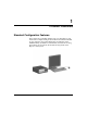
1 Product Features Standard Configuration Features The Compaq Evo™ Desktop features may vary depending on your model. For a complete listing of the hardware and software installed in your computer, run Compaq Diagnostics for Windows or the INSPECT utility (available on some models). Instructions for using these utilities are provided in the Troubleshooting Guide on the Reference Library CD.
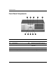
Product Features Front Panel Components Front Panel Components 1 Diskette Drive Activity Light 6 Hard Drive Activity Light 2 Power Button 7 Microphone Connector (optional) 3 Diskette Eject Button 8 Universal Serial Bus (USB) (optional) 4 CD-ROM Drive Busy Indicator 9 Stereo Headphone Jack (optional) 5 CD-ROM Eject Button - Power On Light 1–2 Hardware Reference Guide
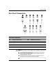
Product Features Rear Panel Components Rear Panel Components 1 Power Cord Connector 7 Parallel Port Connector 2 Voltage Select Switch 8 Microphone Connector 3 Keyboard Connector 9 Line-In Audio 4 Mouse Connector - Line-Out Audio 5 Universal Serial Bus (USB) q Serial Connector 6 RJ-45 Connector Å■ WARNING: To reduce the risk of electric shock or damage to the equipment: ■ ■ Hardware Reference Guide Do not disable the power supply cord grounding plug.
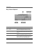
Product Features Easy Access Keyboard Compaq Easy Access Keyboard Components 1 Ctrl Key Used in combination with another key; its effect depends on the application software you are using. 2 Windows Logo Key* Used to open the Start menu in Microsoft Windows. Used in combination with other keys to perform other functions. 3 Alt Key Used in combination with another key; its effect depends on the application software you are using.
Product Features Compaq Easy Access Keyboard Components (Continued) 6 Editing Keys Includes the following: Insert, Home, Page Up, Delete, End, and Page Down. ✎ Holding down Ctrl and Alt while pressing Delete allows you to restart your computer. 7 Num Lock light Indicates whether the Num Lock feature is on or off. 8 Caps Lock light Indicates whether the Caps Lock feature is on or off. 9 Scroll Lock light Indicates whether the Scroll Lock feature is on or off.
Product Features Easy Access Paper Icon Insert The paper icon insert functions as a visual aid in identifying the programmed destination of each Easy Access Button. Whenever you reprogram an Easy Access Button, use the Paper Insert Template document to select and print an icon that reflects the new button assignment. The Paper Insert Template.doc is installed, by default, under C:\Program files\Compaq\Easy Access Keyboard. For proper alignment, the spacing around the icons may require adjustment.
Product Features Serial Number Location Each computer has a unique serial number which may be located on the cover top 1 or the rear panel 2 of the computer. Keep this number available for use when contacting Compaq customer service for assistance.
Product Features 1–8 Hardware Reference Guide
2 Hardware Upgrades Serviceability Features Your computer includes features that make it easier to upgrade and service. Installation Sequence It is very important that you follow this sequence of steps to ensure the proper installation of any optional equipment. For more information about Computer Setup, refer to the Computer Setup Guide. 1. If the computer is already on, turn it off and disconnect the power cord from the wall outlet.
Hardware Upgrades 3. Install any optional equipment. See the applicable sections of this guide or to the documentation provided with the optional equipment for instructions. 4. Replace the computer cover. 5. Turn on the monitor, computer, and any devices you want to test. 6. Reconfigure the computer, if necessary. Refer to the Computer Setup Guide for instructions about using Computer Setup.
Hardware Upgrades Removing the Computer Cover To remove the computer cover: 1. Shut down the operating system properly, then power off the computer and any external devices. 2. Disconnect the power cord from the power outlet, and disconnect any external devices. Ä CAUTION: Before removing the computer cover, ensure that the computer is turned off and that the power cord is disconnected from the electrical outlet. 3. Loosen the two captive thumbscrews that secure the cover to the computer chassis. 4.
Hardware Upgrades Replacing the Computer Cover To replace the computer cover: 1. Hold the cover over the chassis, then rest the guide tabs located inside the cover on the diagonal ramps at the rear of the chassis. 2. Slide the cover along the ramps and into place on the chassis. 3. Tighten the two captive thumbscrews.
Hardware Upgrades Removing the Front Bezel 1. Shut down the operating system properly, then power off the computer and any external devices. Disconnect the power cord from the power outlet and disconnect any external devices. 2. Remove the computer cover. 3. Pull up on the two release tabs, then rotate the front bezel away from the chassis to release it.
Hardware Upgrades Installing Additional Memory The computer comes with Synchronous dynamic random access memory (SDRAM) dual inline memory modules (DIMMs). DIMMs The memory sockets on the Intel 815E and 845 chipset-based system board can be populated with industry-standard DIMMs. These memory module slots are populated with at least one preinstalled memory module. To achieve the maximum memory support, you may be required to replace the preinstalled DIMM with a higher capacity DIMM.
Hardware Upgrades Installing DIMMs Ä CAUTION: Your memory module sockets have gold metal contacts. When upgrading your memory, it is important to use memory modules with gold metal contacts to prevent corrosion and/or oxidation resulting from having incompatible metals in contact with each other. Ä CAUTION: Static electricity can damage the electronic components of the computer or optional cards.
Hardware Upgrades 3. Open both latches of the memory module socket 1, and insert the memory module into the socket 2. Installing a DIMM Begin by installing a module into the socket nearest the preinstalled module, and install the modules following the numerical order of the sockets. A memory module can be installed in only one way. Match the notch on the module with the tab on the memory socket. Push the module down into the socket, ensuring that the module is fully inserted and properly seated 3.
Hardware Upgrades Installing or Removing an Expansion Card Removing an Expansion Slot Cover 1. Shut down the operating system properly, then power off the computer and any external devices, then disconnect the power cord from the power outlet. 2. Remove the computer cover and locate the correct vacant slot in the computer chassis. 3. Remove the screw securing the slot cover, then remove the expansion slot cover from the slot as illustrated.
Hardware Upgrades Removing or Installing an Expansion Card 1. Shut down the operating system properly, then power off the computer and any external devices, then disconnect the power cord from the power outlet. 2. Remove the computer cover. 3. If installing an expansion card, skip to step 8. 4. To remove an installed expansion card, disconnect any cables attached to the expansion card. 5. Remove the screw at the side of the expansion slot. 6.
Hardware Upgrades 7. Store the card in anti-static packaging. 8. Install an expansion slot cover or new expansion card to close the open slot. 9. If not installing a new expansion card, skip to step 11. 10. To install a new expansion card in an open slot, remove the expansion slot cover. 11. Slide the expansion card into the expansion slot and press it firmly into place.
Hardware Upgrades Drive Positions 1 One standard 3.5-inch, 1.44-MB diskette drive mounted with a drive adapter in the 5.25-inch, one-third height bay (labeled as drive bay 3) 2 3 Two internal 3.5-inch, one-third height bays for hard drives (labeled as drive bays 4 and 5) 4 5 Two 5.25-inch, half-height bays for optional drives (labeled as drive bays 1 and 2) To verify the type and size of the storage devices installed in your computer, run Compaq Computer Setup.
Hardware Upgrades Removing a Drive from the Drive Bay 1. Shut down the operating system properly, then power off the computer, disconnect the power cord from the power outlet, and remove the computer cover. 2. Remove the front bezel. 3. Disconnect the drive power and signal cables and, if it is a CD-ROM or DVD-ROM drive, disconnect the audio connector. 4. If removing a hard drive, lift up on the power switch bracket, then rotate down to gain access to the drive bay. 5.
Hardware Upgrades Removing a Drive from the Drive Bay 7. Remove the drive from the drive bay and store in anti-static packaging. Installing Additional Drives The computer supports up to five drives which may be installed in various configurations. When installing additional drives, follow these guidelines: 2–14 ■ For optimal performance, connect hard drives to the primary controller. Connect expansion devices, such as CD-ROM, IDE tape, and diskette drives to the secondary controller.
Hardware Upgrades Ä■ CAUTION: To prevent loss of work and damage to the computer or drive: If you are inserting or removing a hard drive, shut down the operating system properly, then turn off the computer. Do not remove a hard drive while the computer is on or in standby mode. ■ Before handling a drive, ensure that you are discharged of static electricity. While handling a drive, avoid touching the connector.
Hardware Upgrades Connecting Cables Remove the appropriate bezel blank from the front bezel. See the section “Removing Bezel Blanks” for more information. 7. Replace the front bezel. 8. Replace the computer cover. 9. Reconfigure the computer, if necessary. Installing a Hard Drive into a 3.5-inch Drive Bay does not support mixing IDE and SCSI hard drives in the ✎ Compaq same system. If you are replacing a hard drive in bay 4 or bay 5, it should be of the same type. To install a hard drive in a 3.
Hardware Upgrades 3. Lift up on the power switch bracket, then rotate down to gain access to the drive bay. Removing the Power Switch Bracket 4. Insert the hard drive into the bay from the front of the chassis. Push it in until it locks into place. sure that the power switch LED cables remain under the hard ✎ Be drive.
Hardware Upgrades 5. Connect the signal 1 and power 2 cables to the hard drive. Connecting Cables 6. Connect the opposite end of the cables to the appropriate system board connector. 7. Lift the power switch bracket up and into position on the front of the chassis. 8. Replace the front bezel. 9. Replace the computer cover. 10. Reconfigure the computer, if necessary.
A Specifications 3 Compaq Evo Desktop (Intel Pentium 4) Dimensions Height Width Depth Approximate Weight Weight Supported (maximum distributed load) Temperature Range Operating Nonoperating Relative Humidity (noncondensing) Operating Nonoperating Maximum Altitude (unpressurized) Operating Nonoperating Power Supply Operating Voltage Range Rated Voltage Range* Rated Line Frequency Hardware Reference Guide 5.72 in 15.25 in 17.90 in 14.53 cm 38.74 cm 45.47 cm 25 lb 11.34 kg 100.0 lb 45.
Specifications Compaq Evo Desktop (Intel Pentium 4) (Continued) Power Output Rated Input Current (maximum)* Heat Dissipation Maximum Nominal 235 W 235 W 4A 2A 1234 BTU/hr 617 BTU/hr 311 kg-cal/hr 155 kg-cal/hr *This system utilizes a full-ranging, active power factor corrected power supply to greatly reduce the input current amplitude and harmonics. No input voltage select switch is required.
Specifications Compaq Evo Desktop (Intel Pentium III/Celeron) (Continued) Power Supply Operating Voltage Range Rated Voltage Range* Rated Line Frequency Power Output Rated Input Current (maximum)* Heat Dissipation Maximum Nominal 90-132 VAC 100-127 VAC 50-60 Hz 145 W 5A 760 BTU/hr 380 BTU/hr 180-264 VAC 200-240 VAC 50-60 Hz 145 W 2.5 A 192 kg-cal/hr 96 kg-cal/hr *This system utilizes a full-ranging, active power factor corrected power supply to greatly reduce the input current amplitude and harmonics.
Specifications A–4 Hardware Reference Guide
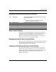
B Hard Drive Installation Guidelines Using the Cable-Select Feature with Ultra ATA Devices Optional drives are available from Compaq in kits that include a special drive cable. The configuration of the drive employs a cable-select feature that identifies the drive as device 0 (primary drive) or device 1 (secondary drive). Device 1 is the drive connected to the cable’s middle connector. Device 0 is the drive connected to the cable’s end connector (applies only to 80-conductor ATA cables).
Hard Drive Installation Guidelines Guidelines for Installing Ultra ATA Devices When installing additional Ultra ATA drives, follow these guidelines: ■ If using multiple Ultra ATA devices, Compaq recommends that the devices be split between the primary and secondary Ultra ATA channels for optimum performance. Use an additional Ultra ATA cable to connect the additional device to the system board.
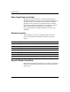
Hard Drive Installation Guidelines SCSI Devices This section contains information relating to SCSI device guidelines and installation. Guidelines for Using SCSI Devices When installing and operating SCSI devices, you must follow these guidelines: ■ A single Ultra SCSI controller supports up to seven SCSI devices per channel. ■ Each Wide-Ultra SCSI, Ultra-Wide SCSI, Wide Ultra2 SCSI, Ultra 320 SCSI, or Ultra 160 SCSI controller supports up to 15 SCSI devices per channel.
Hard Drive Installation Guidelines ■ Every SCSI chain or circuit must be terminated (closed) at both ends. Termination can be accomplished through one of the following methods: ❏ Using a cable with a built-in terminator. This cable was shipped with your computer. ❏ Using a cable with a terminating resistor plug in the last connector. ❏ Connecting a SCSI device with its termination enabled into the last connector.
Hard Drive Installation Guidelines Guidelines for Installing Optional SCSI Devices you mix Ultra ATA and SCSI hard drives in the same system, the ✎ IfUltra ATA drive will be the boot drive unless the boot order is changed in the F10 Setup. When replacing a hard drive, the replacement drive should be of the same type as the drive being removed. If you are replacing an Ultra ATA hard drive with a SCSI hard drive, you will need a multimode Low Voltage Differential (LVD) SCSI cable option kit.
Hard Drive Installation Guidelines SCSI Cables The front drive bays are available for installing or connecting mass storage SCSI devices. Using a SCSI Cable Select models ship with a multimode SCSI cable that supports Low Voltage Differential (LVD) or single-ended devices. The cable accommodates up to three SCSI devices in the front drive bay area (UATA models do not have the SCSI cable).
Hard Drive Installation Guidelines A menu displays with the following options: ■ Configure/View Host Adapter Settings ❏ ❏ ■ SCSI Bus Interface Definitions ◆ Host Adapter SCSI ID ◆ SCSI Parity Checking ◆ Host Adapter SCSI Termination Additional Options ◆ Boot Device Options ◆ SCSI Device Configuration ◆ Advanced Configuration Options SCSI Disk Utilities Lists all SCSI devices and SCSI ID numbers additional information about configuring POST message ✎ For display status, refer to the Compute
Hard Drive Installation Guidelines To determine if your computer contains a Quiet Drive or to activate Quiet mode, complete the following steps: 1. Turn on or restart the computer. If you are in Windows, click Start > Shut Down > Restart the Computer. 2. When the F10 = Setup message displays in the lower-right corner of the screen, press the F10 key. do not press the F10 key while the message is displayed, you ✎ Ifmustyourestart the computer to access the utility. 3.
C Battery Replacement The battery that comes with your computer provides power to the real-time clock and has a minimum lifetime of about three years. When replacing the battery, use a battery equivalent to the battery originally installed on your computer. Your computer comes with a 3-volt lithium coin cell battery. lifetime of the lithium battery can be extended by plugging the ✎ The computer into a live AC wall socket. The lithium battery is only used when the computer is NOT connected to AC power.
Battery Replacement Ä CAUTION: Static electricity can damage the electronic components of the computer or optional equipment. Before beginning these procedures, ensure that you are discharged of static electricity by briefly touching a grounded metal object. 1. If you have locked the Smart Cover Lock, use Computer Setup to unlock the lock and disable the Smart Cover Sensor. 2.
Battery Replacement b. Slide the replacement battery into position, positive side up. The battery holder automatically secures the battery in the proper position. Type 2 a. To release the battery from its holder, squeeze the metal clamp that extends above one edge of the battery. b. When the battery pops up, lift it out.
Battery Replacement c. To insert the new battery, slide one edge of the replacement battery under the holder’s lip with the positive side up. Push the other edge down until the clamp snaps over the other edge of the battery. Replacing a Coin Cell Battery (Type 2) the battery has been replaced, use the following steps to ✎ After complete this procedure. 5. Replace the computer cover or access panel. 6. Plug in the computer and turn on power to the computer. 7.
D Security Lock Provisions Installing a Security Lock There are several different security locks that may be used to secure the computer. The following illustrations portray some of the available security provisions which vary by model. Because of chassis differences, the slots may be located in a different position than shown.
Security Lock Provisions Installing Compaq Type 2 Security Bracket (may vary by model) Å D–2 WARNING: To avoid injury, use care in handling the separated pieces of the security bracket; metal edges may be sharp. Be sure to install the bracket so that sharp edges do not extend from the edges of the computer chassis.
Security Lock Provisions Installing a Kensington Cable Lock with a Compaq Type 2 Bracket (may vary by model) Å WARNING: To avoid injury, use care in handling the separated pieces of the security bracket; metal edges may be sharp. Be sure to install the bracket so that sharp edges do not extend from the edges of the computer chassis.
Security Lock Provisions Installing a Kensington Cable Lock (may vary by model) Installing a Kensington Cable Lock (may vary by model) D–4 Hardware Reference Guide
E Electrostatic Discharge A discharge of static electricity from a finger or other conductor may damage system boards or other static-sensitive devices. This type of damage may reduce the life expectancy of the device. Preventing Electrostatic Damage To prevent electrostatic damage, observe the following precautions: ■ Avoid hand contact by transporting and storing products in static-safe containers. ■ Keep electrostatic-sensitive parts in their containers until they arrive at static-free workstations.
Electrostatic Discharge ■ Use heelstraps, toestraps, or bootstraps at standing workstations. Wear the straps on both feet when standing on conductive floors or dissipating floor mats. ■ Use conductive field service tools. ■ Use a portable field service kit with a folding static-dissipating work mat. If you do not have any of the suggested equipment for proper grounding, contact your Compaq authorized dealer, reseller, or service provider.
F Routine Computer Care and Shipping Preparation Routine Computer Care Follow these suggestions to take care of your computer and monitor: ■ Operate the computer on a sturdy, level surface. Leave a 3-inch (7.6-cm) clearance at the back of the system unit and above the monitor to permit the required airflow. ■ Never operate the computer with the cover or side panel removed. ■ Never restrict the airflow into the computer by blocking the front vents or air intake.
Routine Computer Care and Shipping Preparation CD-ROM Drive Precautions Be sure to observe the following guidelines while operating or cleaning your CD-ROM drive. Operation ■ Do not move the drive during operation. This may cause it to malfunction during reading. ■ Avoid exposing the drive to sudden changes in temperature, as condensation may form inside the unit. If the temperature suddenly changes while the drive is on, wait at least one hour before you turn off the power.
Routine Computer Care and Shipping Preparation Shipping Preparation Follow these suggestions when preparing to ship your computer: 1. Back up the hard drive files on PD discs, tape cartridges, or diskettes. Be sure that the backup media is not exposed to electrical or magnetic impulses while stored or in transit. hard drive locks automatically when the system power is ✎ The turned off. 2. Remove and store any program diskettes from the diskette drives. 3.
Routine Computer Care and Shipping Preparation F–4 Hardware Reference Guide
Index B H battery replacement C–1 bezel blanks, removing 2–5 hard drive activity light 1–2 installation guidelines B–1 installing 2–16 height A–1, A–2 C CD-ROM drive busy indicator 1–2 eject button 1–2 installing 2–15 Components Keyboard 1–4 components front panel 1–2 rear panel 1–3 computer access panel, removing 2–3 computer access panel, replacing 2–4 computer care F–1 D depth A–1, A–2 diskette drive activity light 1–2 drive positions 2–12 DVD-ROM drive installing 2–15 E electrostatic discharge E–1
Index R removing bezel blanks 2–5 computer access panel 2–3 drive from drive bay 2–13, 2–14 expansion card 2–9 expansion slot cover 2–9 front bezel 2–5 S SCSI controller B–5 SCSI device guidelines B–3 SCSISelect utility B–6 security lock provisions D–1 serial connector 1–3 Index–2 serial number location 1–7 shipping preparation F–1 specifications A–1 stereo headphone jack 1–2 switch, voltage select 1–3 U Ultra ATA devices B–1 USB 1–2, 1–3 V voltage select switch 1–3 W weight A–1, A–2 width A–1, A–2 W