Foreword Notice The information in this guide is subject to change without notice. COMPAQ COMPUTER CORPORATION SHALL NOT BE LIABLE FOR TECHNICAL OR EDITORIAL ERRORS, OR OMISSIONS CONTAINED HEREIN; NOR FOR INCIDENTAL OR CONSEQUENTIAL DAMAGES RESULTING FROM THE FURNISHING, PERFORMANCE, OR USE OF THIS MATERIAL. This guide contains information protected by copyright. No part of this guide may be photocopied or reproduced in any form without prior written consent from Compaq Computer Corporation.
the right to make changes in its COMPAQ PORTABLE 386 Personal Computer without notice. Accordingly, the diagrams and procedures in this document may not apply to the computer you are servicing. >>>>>>>>>>>>>>>>>>>>>>>>>>>>>>>>>>>>>>><<<<<<<<<<<<<<<<<<<<<<<<<<<<<<<<<<<<<<< CAUTION Only trained technicians should attempt to repair this equipment. All troubleshooting and repair procedures are detailed to allow subassembly/module level repair only.
Chapter 1. Introduction Chapter 1.1 Summary of Text This guide contains ten chapters which are summarized below: Chapter 1. INTRODUCTION provides a brief summary of the contents of each chapter in the guide, a list of needed tools and supplies, and a list of additional reference documents. Chapter 2. OPERATING AND PERFORMANCE SPECIFICATIONS provides operating and performance specifications for the COMPAQ PORTABLE 386 Personal Computer. Chapter 3.
o o o o o o o o Torx Angle T-15 Screwdriver 3/16 Inch Open End Wrench Integrated Circuit (IC) Removal Tool Integrated Circuit (IC) Insertion Tool Modem Terminating Plug DIAGNOSTICS Program Parallel Interface Loopback Plug Serial Interface Loopback Plug Chapter 1.
o MS-DOS Version 4 Software and Documentation (PN 114493-001 and PN 114496-001) o MS-DOS VERSION 3 REFERENCE GUIDE (PN 114024-001) o BASIC VERSION 3 REFERENCE GUIDE (PN 104030-001) o MICROSOFT Operating System/2 Standard Version 1.
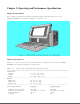
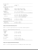
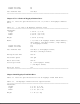
Chapter 2. Operating and Performance Specifications Chapter 2.1 Introduction This chapter provides operating and performance specifications for the COMPAQ PORTABLE 386 Personal Computer (Figure 2-1). Chapter 2.2 System Unit Table 2-1 lists the electrical and mechanical specifications for the COMPAQ PORTABLE 386 Personal Computer system unit. Table 2-1. Electrical and Mechanical Specifications ============================================================================== Dimensions: Height 9.8 in. (24.
-----------------------------------------------------------------------------AC Power Cord: Length 6 ft (1.
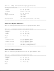
Table 2-3. COMPAQ Dual Mode Plasma Display Specifications ============================================================================== Viewing Area Dimensions: Height 5.2 in. (13.2 cm) Width 8.3 in. (21.1 cm) Diagonal 10.0 in. (25.4 cm) Weight 2.0 lb. (0.9 kg) Graphic Resolution 640 x 400 640 x 200 320 x 200 Text Resolution 640 x 400 (80 characters x 25 lines) ============================================================================== Chapter 2.5 1.
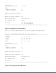
Tracks per Inch Number of Tracks 48 40 Data Transfer Rate 250 Kb/s ============================================================================== Chapter 2.7 3 1/2 Inch 1.44 Megabyte Diskette Drive Table 2-6 lists the specifications for the 3 1/2 inch 1.44 megabyte diskette drive. Table 2-6. 3 1/2 Inch 1.44 Megabyte Diskette Drive ============================================================================== Dimensions: Height 1.00 in. (2.5 cm) Depth 5.91 in. (15.0 cm) Width 4.00 in. (10.
Drive Type (used in SETUP program) 17 or 43 Media: Number of Surfaces Tracks per Surface 4 805 Number of Logical Data Heads 5 Number of Logical Cylinders 980 Average Access Time less than 30 ms Data Transfer Rate 8 Mb/s Interleave 1:1 for Drive Type 43 3:1 for Drive Type 17 ============================================================================== Chapter 2.9 100 Megabyte Fixed Disk Drive Table 2-8 lists the specifications for the 100 megabyte fixed disk drive. Table 2-8.
Table 2-9 lists the specifications for the 110 megabyte fixed disk drive. Table 2-9. 110 Megabyte Fixed Disk Drive Specifications ============================================================================== Dimensions: Height 1.62 in. (4.1 cm) Depth 5.75 in. (14.6 cm) Width 4.00 in. (10.2 cm) Weight 1.8 lb (0.
============================================================================== Dimensions: Height 3.4 in. (8.6 cm) Depth 0.7 in. (1.9 cm) Width 5.4 in. (13.7 cm) Type Bell 103J and CCITT V.21 protocol at 300 baud Bell 212A and CCITT V.22 protocols at 1200 baud CCITT V.22bis protocol at 2400 baud -----------------------------------------------------------------------------International modem specifications available locally.
Table 2-14.
(noncondensing) Nonoperating Not less than 5% or more than 90% (noncondensing) -----------------------------------------------------------------------------Controller 1:1 interleave buffered ESDI external fixed disk drive controller board installs in one 8/16 bit expansion slot in the system unit.
Chapter 3. Power On Self Test (POST)/Problem Isolation Chapter 3.0 Introduction This chapter lists the assemblies checked by the Power On Self Test (POST) and briefly describes the types of error codes that can occur. The chapter also includes problem isolation procedures and a flowchart for quick reference. Chapter 3.1 POST POST is a series of diagnostic tests that automatically run on the COMPAQ PORTABLE 386 Personal Computer when the system is turned on.
printer, remove the loopback plug from the parallel interface and connect the printer instead. 6. Reconnect the AC power cord to a well grounded AC outlet. 7. Insert the latest version of the COMPAQ DIAGNOSTICS diskette into Drive A (Drive Position 1), and push in on the drive button. 8. Turn on the computer. See the SUPPORT SOFTWARE MAINTENANCE AND SERVICE GUIDE for detailed information on problem isolation. Chapter 3.
Chapter 4. Setup and Inspect Chapter 4.0 Introduction Please consult the SUPPORT SOFTWARE MAINTENANCE AND SERVICE GUIDE for current information on SETUP and INSPECT.
Chapter 5. Diagnostics Program Chapter 5.0 Introduction Please consult the SUPPORT SOFTWARE MAINTENANCE AND SERVICE GUIDE for current information on DIAGNOSTICS.
Chapter 6. Error Messages and Codes Chapter 6.1 Introduction This chapter provides Power On Self Test error messages, DIAGNOSTIC error codes, and memory error codes. The messages and codes are given in tables that list the message or error code, a description of the error, and the probable failure or action required to resolve the error condition. Chapter 6.2 Power On Self Test Messages An error message results if a problem is encountered during the Power On Self Test.
304 - Keyboard or System Unit Error None Keyboard or 1. Replace keyboard. system board 2. Replace system board. failure ----------------------------------------------------------------------------401 - Printer None System board Replace system board. Interface Error failure ----------------------------------------------------------------------------402 - Monochrome 1 Long, System board or 1. Replace plasma display Adapter Error 2 Short plasma display controller board controller board 2.
the problem. After completing each step, run the DIAGNOSTICS Program to verify that the error condition has been corrected. If the error code reappears, perform the next step, then run the DIAGNOSTICS Program. Continue until the DIAGNOSTICS Program no longer detects an error condition. The error codes are in the form of AYY - XX or AAYY - XX. A or AA represents the faulty subassembly. YY denotes the test or action that failed. XX denotes a specific problem.
test failed 102 - 11 Numeric coprocessor speed test failed 102 - 12 Numeric coprocessor pattern test failed 102 - 14 Switch indicates no coprocessor present and retest.
105 - 12 Port 61, bit 2 not at zero. 105 - 13 No interrupt generated by fail safe timer. 105 - 14 NMI not triggered by fail safe timer. 106 - 01 Keyboard controller self test failed. 107 - 01 CMOS RAM test failed. 108 - 02 CMOS interrupt test failed. 108 - 03 CMOS interrupt test, CMOS not properly initialized.
112 - 08 Speed test unable to enter auto mode. 112 - 09 Speed test unable to enter high mode. 112 - 10 Speed test high mode out of range. 112 - 11 Speed test auto mode out of range. 112 - 12 Speed test variable speed mode inoperative. 113 - 01 Protected mode test failed.
204 - 02 Error during saving program memory in address test. 204 - 03 Error during restore of program memory in address test. 204 - 04 A20 address test failed. -----------------------------------------------------------------------------Error Code Error Description Recommended Action -----------------------------------------------------------------------------204 - 05 Page hit address test failed. Replace the appropriate memory module(s) or memory board and 205 - 01 Walking I/O test failed.
303 - 01 Keyboard LED test, 8042 self test failed. 303 - 02 Keyboard LED test, retest test failed. 303 - 03 Keyboard LED test, retest failed. 303 - 04 Keyboard LED test, LED command test failed. 303 - 05 Keyboard LED test, LED command test failed.
402 - 03 Printer data and control registers failed. 3. 402 - 04 Printer loopback failed. 4. 402 - 05 Printer loopback and data registers failed. 5. 402 - 06 Printer loopback and control registers failed. 402 - 07 Printer loopback, data, and control registers failed. 402 - 08 Printer interrupt test failed. 402 - 09 Printer interrupt and data registers failed. Replace the Serial/Parallel Interface Board, if applicable, and retest. Replace the printer and/or the printer cable and retest.
2. 504 - 01 Video character set test failed. 505 - 01 Video 80 x 25 mode 9 x 14 character cell test failed. 506 - 01 Video 80 x 25 mode 8 x 8 character cell test failed. 507 - 01 Video 40 x 25 mode test failed. 508 - 01 Video 320 x 200 mode color set 0 test failed. 509 - 01 Video 320 x 200 mode color set 1 test failed. 510 - 01 Video 640 x 200 mode test failed. 511 - 01 Video screen memory page test failed. 512 - 01 Video gray scale test failed. 514 - 01 Video white screen test failed.
601 - xx Format Test 601 - 05 Failed to reset controller 3. 601 - 09 Failed to format a track 4. 601 - 23 Failed to set drive type in ID media 5. 602 - xx Diskette Read Test 602 - 01 Exceeded maximum soft error limit 602 - 02 Exceeded maximum hard error limit 602 - 03 Previously exceeded maximum soft error limit 6. the system board and retest (see Chapter 9, "Jumper and Switch Settings"). Check the diskette power and signal cable. Replace the diskette power and signal cables and retest.
605 - xx Diskette ID Media Test The following steps apply to error codes 600 - xx through 699 - 00: 605 - 20 Failed to get drive type 605 - 24 Failed to read diskette media 605 - 25 Failed to verify diskette media 3. 606 - xx Diskette Speed Test 4. 606 - 26 Failed to read media in speed test 5.
Code Error Description Recommended Action -----------------------------------------------------------------------------1101 - xx Asynchronous Communications The following steps apply to Interface Test error codes 1101 - xx: 1101 - 01 UART DLAB bit failed. 1101 - 02 Line input or UART fault. 1101 - 03 Address line fault. 1101 - 04 Data line fault. 1101 - 05 UART control signal failed. 1101 - 06 UART THRE bit failed. 1101 - 07 UART DATA READY bit failed. 1101 - 08 UART TX/RX buffer failed.
Error Code Error Description Recommended Action -----------------------------------------------------------------------------1201 - xx Modem Internal Loopback Test The following steps apply to error codes 1201 - 01 through 1210 - 11: 1201 - 01 UART DLAB bit failed. 1. Check the jumper settings on 1201 - 02 Line input or UART failed. the system board (see Chapter 9, "Jumper and Switch Settings"). 1201 - 03 Address line fault. 2. Check the modem connection to the 32 bit memory/modem 1201 - 04 Data line fault.
1203 - 01 Modem external TIP/RING failed. 1203 - 02 Modem external DATA TIP/RING failed. 1203 - 03 Modem line termination failed. -----------------------------------------------------------------------------Error Code Error Description Recommended Action -----------------------------------------------------------------------------1204 - xx Modem Auto Originate Test The following steps apply to error codes 1201 - 01 through 1210 - 11: 1204 - 01 Modem timed out waiting for SYNC. 1.
retry limit. 1205 - 04 RCV exceeded carrier lost limit. 1205 - 05 XMIT exceeded carrier lost limit. 1205 - 06 Time out waiting for dial tone. 1205 - 07 Dial number string too long. 1205 - 08 Modem timed out waiting for remote response. 5. Replace the system board and retest. 1205 - 09 Modem exceeded maximum redial limit.
1210 - 09 Modem exceeded maximum redial limit. 1210 - 10 Line quality prevented remote connection. 1210 - 11 Modem timed out waiting for remote connection. ============================================================================== Table 6-11.
1701 - 59 Failed to read sector buffer. 1701 - 66 Failed to initialize fixed disk drive parameter. 1702 - xx Fixed Disk Drive Read Test 1702 - 01 Exceeded maximum soft error limit. 1702 - 02 Exceeded maximum hard error limit. 1702 - 03 Previously exceeded maximum soft error limit. 4. and retest. Replace the system board and retest. 1702 - 04 Previously exceeded maximum hard error limit.
soft error limit. 1703 - 04 Previously exceeded maximum hard error limit. 1703 - 05 Failed to reset controller. 1703 - 06 Fatal error while reading. 1703 - 07 Fatal error while writing. 1703 - 08 Failed compare of write/ read buffers. 1703 - 40 Cylinder 0 error. 1703 - 55 Cylinder 1 error. 1703 - 63 Failed soft error rate. 1703 - 65 Exceeded maximum bad sector per track. 2. 3. 4. settings and retest (see Chapter 9, "Jumper and Switch Settings").
1704 - 06 Fatal error while reading. -----------------------------------------------------------------------------Error Code Error Description Recommended Action -----------------------------------------------------------------------------1704 - 40 Cylinder 0 error. The following steps apply to error codes 1700 - xx through 1717 - 73: 1704 - 55 Cylinder 1 error. 1. Check the system board jumper 1704 - 65 Exceeded maximum bad sector settings and retest per track.
1708 - 09 Format track bad failed. 1708 - 42 Recalibrate drive failed. 1708 - 43 Failed to format a cylinder bad. 1708 - 58 Failed to write sector buffer. 1708 - 59 Failed to read sector buffer.
1714 - 10 Failed diskette sector wrap during read. 1714 - 20 Failed to get diskette drive type. 1714 - 24 Failed to read diskette media. 1714 - 25 Failed to verify diskette media. 1714 - 40 Cylinder 0 error. 1714 - 48 Failed to move disk table to RAM. 1714 - 49 Failed to read diskette media in File Write Test. 1714 - 50 Failed File I/O Write Test. 1714 - 51 Failed File I/O Read Test. 2. 3. 4. (see Chapter 9, "Jumper and Switch Settings").
Error Code Error Description Recommended Action -----------------------------------------------------------------------------1716 - xx Fixed Disk Drive Conditional The following steps apply to error Format Test codes 1700 - xx through 1717 - 73: 1716 - 01 Exceeded maximum soft error limit. 1716 - 02 Exceeded maximum hard error limit. 1716 - 05 Failed to reset controller. 1716 - 06 Fatal error while reading. 1716 - 07 Fatal error while writing. 1716 - 08 Failed compare of write/ read buffers.
1717 - xx Fixed Disk Drive ECC Test 1717 - 01 Exceeded maximum soft error limit. 1717 - 02 Exceeded maximum hard error limit. -----------------------------------------------------------------------------Error Code Error Description Recommended Action -----------------------------------------------------------------------------1717 - 03 Previously exceeded maximum The following steps apply to error soft error limit.
Error Code Error Description Recommended Action -----------------------------------------------------------------------------1900 - xx Tape Test The following codes apply to error codes 1900 - xx through 1900 - 01 Tape not installed. 1991 - xx: 1900 - 02 Drive installed in other drive 3. 1900 - 26 Cannot identify drive. 1900 - 27 Drive not compatible with controller. 1900 - 92 Tape drive mismatched. 1900 - 93 Tape cartridge mismatched.
1902 - 01 Drive not installed. 1902 - 02 Cartridge not installed. 1902 - 03 Tape motion error. 1902 - 04 Drive busy error. 1902 - 05 Track seek error. -----------------------------------------------------------------------------Error Code Error Description Recommended Action -----------------------------------------------------------------------------1902 - 06 Tape write protected error. The following codes apply to error codes 1900 - xx through 1902 - 09 Unable to format.
1904 - 04 Drive busy error. 1904 - 05 Track seek error. 1904 - 15 Sense error flag. 1904 - 27 Drive not compatible with controller. 1905 - xx Tape Read Test 1905 - 01 Drive not installed. 1905 - 02 Cartridge not installed. 1905 - 03 Tape motion error. -----------------------------------------------------------------------------Error Code Error Description Recommended Action -----------------------------------------------------------------------------1905 - 04 Drive busy error.
1906 - 06 Tape write protected error. 1906 - 14 Drive timeout error. The following codes apply to error codes 1900 - xx through 1991 - xx: 1906 - 16 Block locate (block ID) error. 1. 1906 - 17 Soft error limit exceeded. 2. 1906 - 18 Hard error limit exceeded. 3. 1906 - 19 Write (probably ID error). 1906 - 20 765 Fatal error. 1906 - 24 Fail write protect test. 1906 - 26 Cannot ID drive. 1906 - 27 Drive not compatible with controller. Replace the tape cartridge and retest.
2414 - 01 Video White Screen Test 2416 - 01 Video Noise Pattern Test -----------------------------------------------------------------------------Error Code Error Description Recommended Action -----------------------------------------------------------------------------2417 - 01 Lightpen text mode test The following steps apply to error failed; no response. codes 2417 - xx. 2417 - 02 Lightpen text mode test failed; invalid response. 2421 - 01 VGC and ECG 640 x 200 graphics mode test failed.
1.
Defective Memory Isolation Memory error codes are shown on the display in an 8 digit format (XX000Y ZZ). The XX and Y alphanumeric codes are the key identification points for defective memory isolation. Due to the design of the COMPAQ PORTABLE 386 Personal Computer, the remaining codes in the format are not required for determining memory locations.
Chapter 7. Illustrated Parts Catalog Chapter 7.1 Introduction This chapter provides a spare parts reference for the COMPAQ PORTABLE 386 Personal Computer. The information in each section is presented in tabular form. contains the following columns: Each table o Description - name of the particular part or parts kit. o Part Number - to be used when ordering parts from Compaq Computer Corporation.
Table 7-1. Display Enclosure Assembly ============================================================================== Item Description Part Number -----------------------------------------------------------------------------1. COMPAQ Dual Mode Plasma Display 107381-001 2. Display Filter Assembly 107689-001 3. Display Enclosure 107043-001 4. Keyboard Connector Cover * 107120-001 5. Brightness Control Assembly 107384-001 6. Brightness Control Knob * 107121-001 7.
15. Mandrel * 107386-001 -----------------------------------------------------------------------------* Included in the Miscellaneous Hardware Kit (PN 107386-001). ** Included in the Cable Kit (PN 107382-001). ============================================================================== Chapter 7.3 Portable Enhanced Keyboard Assembly Table 7-2 lists the keyboard assembly for the COMPAQ PORTABLE 386 Personal Computer, which is illustrated in Figure 7-3. Table 7-2.
Table 7-3 lists the spare parts for the COMPAQ PORTABLE 386 Personal Computer chassis rear assembly. Items numbered 1 through 14 are illustrated in Figure 7-4, and items numbered 15 through 34 are illustrated in Figure 7-5. Table 7-3. Chassis - Rear Assembly ============================================================================== Item Description Part Number -----------------------------------------------------------------------------1. Main Housing Enclosure 107072-002 2.
3. Power Supply Ground Subassembly 107624-001 4. Battery 107786-001 5. System Board 107683-001 6. Microprocessor Cover 107617-001 7. System Board Cover 107704-001 8. Rear Panel 107168-001 9. AC Power Cord 101155-001 10. Interface Connector Cover 107737-001 11. 32 Bit Memory/Modem Interface Board 107684-001 12. System ROMs 107796-001 13. RGB Data Cable ** 107386-001 14. Options Compartment Shield 107799-001 15. Front Main Bezel 107034-001 (replaced by 107803-001) 16.
31. 1 to 2 Megabyte Memory Expansion Board 107686-001 32. Display Data Cable Assembly ** 107382-001 33. LED/Speaker Cable 107926-001 34. Keyboard Cable (Internal) 107924-001 -----------------------------------------------------------------------------* Included in the Miscellaneous Hardware Kit (PN 107386-001). ** Included in the Cable Kit (PN 107382-001). ============================================================================== Chapter 7.
5. Mass Storage Device Enclosure 107131-004 6. Fixed Disk Drive Data Cable ** 107798-001 7. Fixed Disk Drive Power Cable ** 101741-003 8. 40 Megabyte Fixed Disk Drive (3:1) 107357-001 (replaced by 142365-001) 40 Megabyte Fixed Disk Drive (1:1 Drive Type 17) 110358-001 (replaced by 142365-001) 40 Megabyte Fixed Disk Drive (1:1 Drive Type 43) 114106-001 (replaced by 142365-001) 100 Megabyte Fixed Disk Drive 107790-001 110 Megabyte Fixed Disk Drive 107982-001 9.
Table 7-5.
4 Megabyte Memory Expansion Board 107688-001 4 Megabyte Memory Extension Board 107685-001 COMPAQ 1200 Baud Internal Modem 107376-001 COMPAQ 2400 Baud Internal Modem 107791-001 Second Serial Interface Board (International) 107871-001 Expansion Unit (complete) 107453-001 Tape Drive Expansion Unit 107785-001 Tape Cartridge (40 Megabyte) 108142-001 Video Graphics Controller Board 109253-001 Video Graphics Color Monitor 109255-001 Video Graphics Monochrome Monitor 109254-001 Intel 80387 (20
Table 7-6 lists the spare parts in the cable kit (PN 107382-001) for the COMPAQ PORTABLE 386 and COMPAQ PORTABLE III Personal Computers. Table 7-6.
Chapter 8. Removal and Replacement Procedures Chapter 8.1 Introduction Before starting the removal procedures, review Chapter 7, "Illustrated Parts Catalog," to become familiar with the various part numbers and locations. After completing all removal and replacement procedures, run the DIAGNOSTICS Program on the COMPAQ PORTABLE 386 Personal Computer to verify the proper operation of the replaced component. Chapter 8.
1. Complete the preparation procedure (see Section 8.2). 2. Detach the keyboard from the system unit. 3. Grasp the keyboard cord near where it connects to the computer. Gently pull it away from the keyboard connector on the computer (Figure 8-2). 4. Slide the keyboard connector cover off of the keyboard cord and set it aside (Figure 8-3).
To replace the keyboard assembly, reverse steps 1 through 4. Chapter 8.4 Rear Panel To remove the rear panel: 1. Complete the preparation procedure (see Section 8.2). 2. Place the computer keyboard side down on a level surface with the rear panel facing upward. 3. Remove the six screws and washers that secure the rear panel to the computer (Figure 8-4). Note that the two screws you removed from the center position are shorter than the other four screws. 4.
>>>>>>>>>>>>>>>>>>>>>>>>>>>>>>>>>>>>>>><<<<<<<<<<<<<<<<<<<<<<<<<<<<<<<<<<<<<<< CAUTION Do not overtighten the screws. >>>>>>>>>>>>>>>>>>>>>>>>>>>>>>>>>>>>>>><<<<<<<<<<<<<<<<<<<<<<<<<<<<<<<<<<<<<<< Chapter 8.5 Interface Connector Cover The interface connector cover protects the 32 bit memory/modem interface connector when nothing is installed in the options compartment.
aside (Figure 8-6). To replace the interface connector cover, reverse steps 1 through 5. Chapter 8.6 Microprocessor Cover To remove the microprocessor cover: 1. Complete the preparation procedure (see Section 8.2). 2. Remove the rear panel (see Section 8.4). 3. Locate the microprocessor cover shown in Figure 8-7.
4. Grasp the microprocessor cover at its edges; gently lift it up and away from the system board and set it aside (Figure 8-8). To replace the microprocessor cover, reverse steps 1 through 4. NOTE: Position the cover so that the edges slanted in go inside the fence and those slanted out go outside the fence. Press the cover securely into place by working from one end to the other.
Chapter 8.7 System Board Cover To remove the system board cover: 1. Complete the preparation procedure (see Section 8.2). 2. Remove the rear panel (see Section 8.4). 3. Remove the interface connector cover, if installed (see Section 8.5). 4. Remove the 32 bit memory/modem interface board, if installed (see Section 8.8). 5. Remove the microprocessor cover (see Section 8.6). 6. Locate the system board cover shown in Figure 8-9. 7.
Chapter 8.8 32 Bit Memory/Modem Interface Board The 32 bit memory/modem interface board connects the memory expansion boards, either internal modem, and the second serial interface board to the system board. If one or a combination of these options is installed, the 32 bit memory/modem interface board will also be in place. To remove the 32 bit memory/modem interface board: 1. Complete the preparation procedure (see Section 8.2). 2. Remove the rear panel (see Section 8.4). 3.
4. Remove the screws securing the 32 bit memory/modem interface board and set them aside. 5. Grasp the 32 bit memory/modem interface board at its edges and, without rocking it, lift it straight up and away from the computer (Figure 8-12). When the 32 bit memory/modem interface board is removed, the options compartment with its two expansion slots is revealed (Figure 8-13).
The top slot holds the second serial interface board or one of the internal modems. Both the COMPAQ 1200 Baud Internal Modem and the COMPAQ 2400 Baud Internal Modem, are approved for use with the COMPAQ PORTABLE 386 Personal Computer. The second slot allows memory expansion using any of three different memory expansion board combinations (see Section 8.8). To replace the 32 bit memory/modem interface board, reverse steps 1 through 4. Chapter 8.
5. Locate the internal modem and modem ground bracket shown in Figure 8-15. 6. Remove the one screw that secures the modem ground bracket to the system board (Figure 8-16).
7. Remove the modem bezel (Figure 8-17). 8. Slide the internal modem out of the options compartment and set it aside (Figure 8-18).
To replace the internal modem option, reverse steps 1 through 8. Chapter 8.10 Second Serial Interface Board (International Only) To remove the second serial interface board: 1. Complete the preparation procedure (see Section 8.2). 2. Remove the rear panel (see Section 8.4). 3. Remove the 32 bit memory/modem interface board (see Section 8.8). 4. Press the top tab and disconnect the LED/speaker and keyboard cables from the system board (Figure 8-19).
5. Locate the second serial interface board shown in Figure 8-20. 6. Slide the second serial interface board out of the options compartment and set it aside (Figure 8-21).
To replace the second serial interface board, reverse steps 1 through 6. Chapter 8.11 Memory Expansion Boards Three memory expansion boards are available for the COMPAQ PORTABLE 386 Personal Computer: o 1 to 2 Megabyte Memory Expansion Board, which comes standard with four sockets and one megabyte of random access memory (RAM). The one megabyte of RAM is in the form of a memory upgrade kit (two 512 Kbyte memory modules), which is installed in two of the sockets.
To remove a memory expansion board: 1. Complete the preparation procedure (see Section 8.2). 2. Remove the rear panel (see Section 8.4). 3. Remove the 32 bit memory/modem interface board (see Section 8.8). 4. Press the top tab and disconnect the LED/speaker and keyboard cables from the system board (Figure 8-22).
5. Locate the memory expansion board shown in Figure 8-23. 6. Slide the memory expansion board out of the options compartment and set it aside (Figure 8-24).
To replace the memory expansion board, reverse steps 1 through 6. Chapter 8.12 Memory Upgrade Kit Each 1 megabyte memory upgrade kit consists of two 512 Kbyte memory modules, which are surface mounted with four 256K x 4, 80 ns RAM chips and two 256K x 1, 80 ns RAM chips. The memory upgrade kits are used on the system board to expand its base one megabyte of standard RAM to two megabytes. The memory upgrade kits also provide the memory capacity of the 1 to 2 megabyte memory expansion board.
5. To release the module, insert a tool, such as a ball point pen, into the hole at one end of the module. 6. Grasp the end of the module, pull up, and "peel" it away from its socket (Figure 8-26). To replace the memory module, simply reinsert it into its socket, then reverse steps 1 through 3.
1. Complete the preparation procedure (see Section 8.2). 2. Remove the rear panel (see Section 8.4). 3. Remove the 32 bit memory/modem interface board (see Section 8.8). 4. Remove the 1 to 2 megabyte memory expansion board (see Section 8.11). 5. Locate the memory module that is to be replaced (Figure 8-27). 6. To release the module, insert a tool, such as a ball point pen, into the hole at one end of the module. 7.
To replace the memory module, simply reinsert it fully into its socket, then reverse steps 1 through 5. Chapter 8.13 System ROM To remove the system ROM: >>>>>>>>>>>>>>>>>>>>>>>>>>>>>>>>>>>>>>><<<<<<<<<<<<<<<<<<<<<<<<<<<<<<<<<<<<<<< CAUTION The ROMs are sensitive to static electricity and are shipped on conductive foam to protect them from accidental electrostatic discharge. Do not remove them from the conductive shipping foam until you are ready to install them.
8. Using an IC removal tool, remove the system ROM (Figure 8-30). 9. Using an IC insertion tool, insert the new ROM into the appropriate sockets (Figure 8-31).
Chapter 8.14 System Board NOTE: The system board and the base pan are one assembly and are removed simultaneously. To remove the system board assembly: 1. Complete the preparation procedure (see Section 8.2). 2. Remove the rear panel (see Section 8.4). 3. Remove the interface connector cover, if installed (see Section 8.5). 4. Remove the 32 bit memory/modem interface board, if installed (see Section 8.8). 5. Remove the microprocessor cover (see Section 8.6). 6.
o o o o o 11. Fixed disk drive power cable LED/speaker cable Keyboard cable Display controller board data cable Battery cable Remove the screws that secure the system board assembly to the main enclosure (Figure 8-33). NOTE: Use a 3/16 inch wrench to remove the standoffs and a Torx screwdriver to remove the screws.
12. Grasp the system board assembly by its edges. the main enclosure. Lift it up and away from 13. Disconnect the RGBI cable assembly from the plasma display controller board (Figure 8-34). To replace the system board, reverse steps 1 through 13.
Chapter 8.15 Plasma Display Controller Board To remove the plasma display controller board: 1. Complete the preparation procedure (see Section 8.2). 2. Remove the rear panel (see Section 8.4). 3. Remove the interface connector cover, if installed (see Section 8.5). 4. Remove the 32 bit memory/modem interface board, if installed (see Section 8.8). 5. Remove the microprocessor cover (see Section 8.6). 6. Remove the system board cover (see Section 8.7). 7.
NOTE: Removing the controller board from its compartment also disconnects it from the display data cable. 13. Disconnect the display controller board data cable from the controller board (Figure 8-37). To replace the controller board, reverse steps 1 through 13.
Chapter 8.16 Mass Storage Device Assembly To remove the mass storage device subassembly: 1. Complete the preparation procedure (see Section 8.2). 2. Remove the rear panel (see Section 8.4). 3. To remove the drive bezel, place your thumb on the rear side of the drive bezel. 4. Pull the drive bezel away from the computer with your thumb. (Figure 8-38). 5.
6. Locate the mass storage device subassembly shown in Figure 8-40. 7. Remove the screw that secures the mass storage device subassembly to the mass storage device enclosure (Figure 8-41).
8. Slide the mass storage device subassembly out of the mass storage device enclosure (Figure 8-42). >>>>>>>>>>>>>>>>>>>>>>>>>>>>>>>>>>>>>>><<<<<<<<<<<<<<<<<<<<<<<<<<<<<<<<<<<<<<< CAUTION When removing the mass storage device subassembly, be sure that the cables do not interfere with the mass storage device enclosure.
To replace the mass storage device subassembly, reverse steps 7 and 8. >>>>>>>>>>>>>>>>>>>>>>>>>>>>>>>>>>>>>>><<<<<<<<<<<<<<<<<<<<<<<<<<<<<<<<<<<<<<< CAUTION When replacing the mass storage device subassembly, be sure that the cables do not interfere with the mass storage device enclosure. >>>>>>>>>>>>>>>>>>>>>>>>>>>>>>>>>>>>>>><<<<<<<<<<<<<<<<<<<<<<<<<<<<<<<<<<<<<<< Reconnect the cables, listed in step 5, to the system board. To replace the bezel and rear panel, reverse steps 1 through 4. Chapter 8.
6. Remove the two screws that secure the drive cover or metal plate covering the front of Drive Position 2 (Figure 8-45).
7. Remove the four screws from the mass storage device subassembly and slide the fixed disk drive assembly out of the mass storage device subassembly (Figure 8-46). To replace the fixed disk drive, reverse steps 1 through 7. Chapter 8.
To remove the diskette drive assembly: 1. Complete the preparation procedure (see Section 8.2). 2. Remove the rear panel (see Section 8.4). 3. Remove the mass storage device subassembly (see Section 8.12). 4. Locate the diskette drive shown in Figure 8-47. 5. Disconnect the diskette drive power and signal cables from the diskette drive (Figure 8-48).
6. Remove the four shoulder bolts from the mass storage device subassembly and slide the diskette drive assembly out of the mass storage device subassembly (Figure 8-49). NOTE: When removing the diskette drive, do not misplace the four vibration isolators shown in Figure 8-49. You must use all four vibration isolators to replace the diskette drive assembly. To replace the diskette drive, reverse steps 1 through 6.
Chapter 8.19 Power Supply To remove the power supply: 1. Complete the preparation procedure (see Section 8.2). 2. Remove the rear panel (see Section 8.4). 3. Remove the interface connector cover, if installed (see Section 8.5). 4. Remove the 32 bit memory/modem interface board, if installed (see Section 8.8). 5. Remove the system board cover (see Section 8.6). 6. Remove the microprocessor cover (see Section 8.7). 7. Remove the system board (see Section 8-14). 8.
10. Disconnect the plasma display data cable and the plasma display power cable ground wire from the power supply (Figure 8-52). 11. Place the computer in an upright position. 12. Place the plasma display at an outward angle and remove the top two screws and washers with an angle Torx screwdriver (Figure 8-53).
13. Lift the plasma display into an upright position and remove the bottom two screws and washers with a Torx screw driver (Figure 8-54). 14. Carefully slide the power supply out of the computer chassis (Figure 8-55).
To replace the power supply, reverse steps 1 through 14. Chapter 8.20 Mass Storage Device Enclosure To remove the mass storage device enclosure: 1. Complete the preparation procedure (see Section 8.2). 2. Remove the rear panel (see Section 8.4). 3. Remove the interface connector cover, if installed (see Section 8.5). 4. Remove the 32 bit memory/modem interface board, if installed (see Section 8.8). 5. Remove the system board (see Section 8.14). 6.
9. 10. Lift the plasma display into an upright position and remove the bottom two screws and washers from the mass storage device enclosure with a Torx screwdriver (Figure 8-57). Carefully slide the mass storage device enclosure out of the computer chassis (Figure 8-58).
To replace the mass storage device enclosure, reverse steps 1 through 10. >>>>>>>>>>>>>>>>>>>>>>>>>>>>>>>>>>>>>>><<<<<<<<<<<<<<<<<<<<<<<<<<<<<<<<<<<<<<< CAUTION Be sure the LED/speaker and keyboard cables are not pinched or exposed when replacing the mass storage devices enclosure. >>>>>>>>>>>>>>>>>>>>>>>>>>>>>>>>>>>>>>><<<<<<<<<<<<<<<<<<<<<<<<<<<<<<<<<<<<<<< Chapter 8.21 LED/Speaker Cable, Keyboard Cable, and LED Assembly To remove the LED/speaker cable, keyboard cable, and LED assembly: 1.
9. 10. Remove the two screws that secure the keyboard cable connector to the keyboard ground strap and computer chassis (Figure 8-60). Locate the LED/speaker and keyboard cables shown in Figure 8-61.
11. Disconnect the LED connector from the LED assembly (Figure 8-62). careful not to bend the pins on the LED assembly connector. 12. Disconnect the speaker from the rail (Figure 8-63).
CAUTION When removing the speaker, do not touch the silver speaker surface. >>>>>>>>>>>>>>>>>>>>>>>>>>>>>>>>>>>>>>><<<<<<<<<<<<<<<<<<<<<<<<<<<<<<<<<<<<<<< 13. Slide the speaker and the LED connector through the slot in the options compartment (Figure 8-64).
14. Disconnect the keyboard cable extension from the keyboard cable. 15. Remove the LED/speaker cable and keyboard cable from the options compartment (Figure 8-65). 16. Remove the eight screws that secure the front main bezel to the main housing enclosure (Figure 8-66).
17. Push the LED assembly forward and snap it out (Figure 8-67). 18. Slide the LED lens out of the computer chassis (Figure 8-68).
To replace the LED assembly and the LED/speaker and keyboard cables, reverse steps 1 through 17. >>>>>>>>>>>>>>>>>>>>>>>>>>>>>>>>>>>>>>><<<<<<<<<<<<<<<<<<<<<<<<<<<<<<<<<<<<<<< CAUTION When replacing the speaker, do not touch the silver speaker surface. >>>>>>>>>>>>>>>>>>>>>>>>>>>>>>>>>>>>>>><<<<<<<<<<<<<<<<<<<<<<<<<<<<<<<<<<<<<<< Chapter 8.22 Plasma Display To remove the Plasma Display: 1. Complete the preparation procedure (see Section 8.2). 2.
3. While holding the display bezel in place with one hand, remove the four screws that secure the display bezel to the display enclosure. These screws are located on the back of the display enclosure (Figure 8-70). 4. Alter removing the four screws, lift the display bezel away from the front of the display enclosure. Be careful to catch the brightness control knob as you remove the display bezel (Figure 8-71).
>>>>>>>>>>>>>>>>>>>>>>>>>>>>>>>>>>>>>>><<<<<<<<<<<<<<<<<<<<<<<<<<<<<<<<<<<<<<< CAUTION Grasp the display by its metal frame and do not touch the display panel. >>>>>>>>>>>>>>>>>>>>>>>>>>>>>>>>>>>>>>><<<<<<<<<<<<<<<<<<<<<<<<<<<<<<<<<<<<<<< 5. Remove the two latches from the display enclosure and set them aside (Figure 8-72). NOTE: For future replacement, notice how the latches are positioned.
6. Locate the plasma display shown in Figure 8-73. 7. Remove the four screws and washers that secure the plasma display to the display enclosure (Figure 8-74).
NOTE: The ground plate comes loose and may hang from the ground wires when the plasma display is removed. 8. Lift the plasma display away from the display ground bracket and tilt it forward to expose the cables. 9. Disconnect the ground plate from the ground wires and remove the grounding foil. 10. Disconnect the display cable, display power cable, and the brightness control knob assembly from the plasma display (Figure 8-75).
11. Disconnect the display power cable ground wires from the plasma display (Figure 8-76). To replace the plasma display, reverse steps 1 through 11. display bezel, replace the brightness control knob. NOTE: If cleaning is required, use isopropyl alcohol.
Chapter 8.23 Plasma Display Filter To remove the plasma display filter: 1. Complete the preparation procedure (see Section 8.2). 2. Complete steps 2 through 4 of Section 8.22. 3. Remove the filter by lifting it up and out of the plasma display enclosure as shown in Figure 8-77. To replace the plasma display filter, reverse steps 1 through 3. Chapter 8.24 Brightness Control Assembly To remove the brightness control assembly: 1. Complete the preparation procedure (see Section 8.2). 2.
4. Push the lower legs of the brightness control assembly upward, and snap the assembly out (Figure 8-79). To replace the brightness control assembly, reverse steps 1 through 4. Chapter 8.
1. Complete the preparation procedure (see Section 8.2). 2. Remove the plasma display (see Section 8.22). 3. Remove the two screws that secure the strain relief clip to the display enclosure (Figure 8-80). 4. Remove the display power cable and the display data cable from the strain relief clip (Figure 8-81).
5. Observe that the display enclosure is attached to the main enclosure by two mandrels and two plasma display hinges (Figure 8-82). 6. Remove the one screw that secures each mandrel to the display enclosure (Figure 8-83).
7. Remove each mandrel from the display enclosure by pushing the mandrel toward the plasma display and lifting it out (Figure 8-84). 8. Remove the four screws that secure the display enclosure to the plasma display hinges (Figure 8-85).
you face the display enclosure) will also remove the display ground (Figure 8-85). 9. 10. Lift the display enclosure away from the main enclosure, being careful to guide the display power cable and display data cable through the slot in the display enclosure (Figure 8-86). Notice that the rollers are still located in the grooves (Figure 8-87).
11. Remove the rollers from the grooves, place them on the mandrels, and set them aside. To replace the display enclosure: 1. Guide the display cable assembly back through the slot in the main enclosure. 2. With the display enclosure in the down position, guide each roller and mandrel back into position and replace the screw. 3. While aligning the display enclosure with the plasma display hinges with one hand, replace the four screws that secure the display enclosure to the plasma display hinges.
1. Complete the preparation procedure (see Section 8.2). 2. Remove the rear panel (see Section 8.4). 3. Remove the 32 bit memory/modem interface board, if installed (see Section 8.5). 4. Remove the system board (see Section 8.10). 5. Remove the plasma display controller board (see Section 8.11). 6. Remove the plasma display (see Section 8.18). 7. Remove the display enclosure (see Section 8.20) 8. Locate the display power cable assembly and the display data cable assembly shown in Figure 8-88.
10. Disconnect the display data cable and display power cable ground wires from the power supply (Figure 8-90). 11. Remove the screw that secures the strain relief bracket to the main enclosure (Figure 8-91).
12. Remove the display data cable connector from the plasma display controller board compartment (Figure 8-92). 13. Guide the display power cable assembly and the display data cable assembly through the opening in the main enclosure wall (Figure 8-93).
NOTE: For future replacement, notice the proper orientation of the display power cable assembly and the display data cable assembly. To replace the display data cable assembly, reverse steps 1 through 13. Chapter 8.27 Handle and Spreader Plate To remove the handle and spreader plate: 1. Complete the preparation procedure (see Section 8.2). 2. Remove the rear panel (see Section 8.4). 3. Remove the interface connector cover, if installed (see Section 8.5). 4.
10. Remove the four screws that secure the plasma display hinges to the main enclosure (Figure 8-95). 11. Locate the handle and spreader plate shown in Figure 8-96.
12. Remove the two screws that secure the handle and spreader plate to the computer chassis. Remove the handle and spreader plate (Figure 8-97). To replace the handle and spreader plate, reverse steps 1 through 12. Chapter 8.
WARNING This computer contains a lithium battery that may explode if mistreated. not abuse, disassemble, or dispose of in fire. Do Use only replacement batteries supplied by Compaq Computer Corporation (PN 107786-001) Disposal of the lithium battery should be accomplished within compliance of local regulations or returned to Compaq Computer Corporation by established parts return methods. >>>>>>>>>>>>>>>>>>>>>>>>>>>>>>>>>>>>>>><<<<<<<<<<<<<<<<<<<<<<<<<<<<<<<<<<<<<<< To remove the battery: 1.
To replace the battery, reverse steps 1 through 7. >>>>>>>>>>>>>>>>>>>>>>>>>>>>>>>>>>>>>>><<<<<<<<<<<<<<<<<<<<<<<<<<<<<<<<<<<<<<< WARNING Use caution when replacing the lithium battery. Be sure the replacement battery is supplied by Compaq Computer Corporation and identified by PN 107786-001. >>>>>>>>>>>>>>>>>>>>>>>>>>>>>>>>>>>>>>><<<<<<<<<<<<<<<<<<<<<<<<<<<<<<<<<<<<<<< NOTE: UPS will not airship (UPS blue label) lithium batteries. Chapter 8.
3. Place the computer, keyboard side down, on a level surface with the rear panel facing up and the handle facing away from you. 4. Pull out on the locking bar that secures the expansion unit to the computer chassis (Figure 8-101). 5. Grasp the expansion unit on each side.
6. Pull the expansion unit up and away from the computer (Figure 8-102). 7. Insert a flat blade screwdriver in each of the four notches on the expansion unit and gently pop up the expansion unit cover (Figure 8-103). 8. Remove the expansion unit cover (Figure 8-104).
9. Remove the retaining screw that secures each optional expansion board to the expansion unit. Gently lift the board(s) up and out of its connector on the circuit board (Figure 8-105). To replace the expansion unit, reverse steps 1 through 9. Chapter 8.
Preparation Procedures Before beginning the removal and replacement procedures, complete the following steps. 1. Turn off the computer. 2. Turn off the 300/600 Megabyte Fixed Disk Drive Expansion Unit (hereafter referred to as the fixed disk drive expansion unit). 3. Disconnect all power to the computer and the fixed disk drive expansion unit. 4. Disconnect the signal cable from the fixed disk drive expansion unit to the computer. 5.
2. Disconnect the 20 pin and 34 pin signal cables from the external interface adapter board in the fixed disk drive expansion unit (Figure 8-107). 3. Disconnect the universal drive power cable from the external interface adapter board in the fixed disk drive expansion unit (Figure 8-108). 4. Remove the three retaining screws securing the fixed disk drive to the fixed disk drive expansion unit (Figure 8-109).
5. Carefully slide the fixed disk drive out of the fixed disk drive expansion unit housing. NOTE: A terminating resistor must be installed on a 300 megabyte fixed disk drive if: o The fixed disk drive is in a 300 Megabyte Fixed Disk Drive Expansion Unit. o The fixed disk drive is the secondary drive in a 600 Megabyte Fixed Disk Drive Expansion Unit. To remove the terminating resistor, complete the following steps: 1.
NOTE: Terminating resistors are located in different positions on the drive depending on the manufacturer. To replace the fixed disk drive in the fixed disk drive expansion unit, reverse steps 1 through 5. Power Supply To remove the power supply from the fixed disk drive expansion unit, complete the following steps. 1. Complete the preparation procedures at the beginning of Section 8.30. 2.
3. Slide the power supply assembly 1/2 inch to 1 inch (1.27 to 2.54 cm) toward the fixed disk drive housing (Figure 8-112). Be sure to clear the tabs on the bottom chassis. These tabs hold the power supply assembly in place. 4. Shift the power supply assembly away from the external adapter board to access the connector on the board. 5. Disconnect the power supply connector from the external interface adapter board and lift the power supply assembly out of the chassis.
To replace the power supply assembly, reverse steps 1 through 5. External Interface Adapter Board To remove the external interface adapter board from the fixed disk drive expansion unit, complete the following steps: 1. Complete the preparation procedures at the beginning of Section 8.30. 2. Disconnect the 20 pin and 34 pin signal cables from the external interface adapter board (Figure 8-113).
3. Disconnect the universal drive power and power supply cables from the external interface adapter board (Figure 8-114). 4. Remove the external interface adapter board. NOTE: Inspect the new external interface adapter board for shipping damage before installing.
To replace the external interface adapter board, reverse steps 1 through 4. NOTE: For internal and external switch settings for the 300/600 Megabyte Fixed Disk Drive Expansion Unit, refer to Chapter 9, "Jumper and Switch Settings.
Chapter 9. Jumper and Switch Settings Chapter 9.1 Introduction This chapter provides jumper and switch settings for the COMPAQ PORTABLE 386 Personal Computer. When using the tables in this chapter, remember that the default settings shown are set for the system as configured by Compaq Computer Corporation. These settings need to be changed only when the system configuration is changed.
NOTE: E12, E18, E22, E24, E25, The following jumper settings are reserved: Pins Pins Pins Pins Pins 1 2 2 1 1 and and and and and 2 3 3 2 2 Figure 9-1 shows the jumper locations on the COMPAQ PORTABLE 386 system board. Chapter 9.3 System Board Jumper Settings Refer to Figure 9-1 for the system board jumper locations. through 9-9 as references for setting each jumper.
E7, Pins 1 and 2 Select primary interrupt (IRQ7) (default) E7, Pins 2 and 3 Select alternate interrupt (IRQ5) ============================================================================== Table 9-2.
Table 9-3. Jumpers E5 and E6 - Select Drive Options ============================================================================== Jumper Setting Function -----------------------------------------------------------------------------E5, Pins 1 and 2 Enables fixed disk drive (default). E5, Pins 2 and 3 Disables fixed disk drive. E6, Pins 2 and 3 Selects primary drive addresses (1FX, 3FX) (default).
-----------------------------------------------------------------------------E19, Pins 1 and 2 Fail safe timer enabled (default). E19, Pins 2 and 3 Fail safe timer disabled. ============================================================================== Table 9-7.
CAUTION Use care when setting the configuration switches on the COMPAQ Enhanced Color Graphics Board. Many of the components on the board are sensitive to static electricity. Be sure that you are discharged of static electricity by briefly touching a metal object. Also, the correct setting of the configuration switches is vital to the operation of the COMPAQ Enhanced Color Graphics Board. Be sure that you set them correctly for your computer system before installing the board.
Configuration Switch Bank SW1 How the COMPAQ Enhanced Color Graphics Board is to be used determines the setting for configuration switch bank SW1. The board can be used as either the only or primary display controller board (the one active at power on or reboot) or secondary display controller board. Refer to Figure 9-2 or 9-3 for the location of configuration switch bank SW1.
-----------------------------------------------------------------------------COMPAQ Color Monitor 80 x 25 OFF OFF OFF ON Monochrome or Compatible Enhanced (640 x 200 Display Color Monitor or COMPAQ resolution) Adapter Dual Mode Monitor or 80 x 25 RGB Color Monitor -----------------------------------------------------------------------------COMPAQ Color Monitor 40 x 25 ON OFF OFF ON Monochrome or Compatible Enhanced (320 x 200 Display Color Monitor or COMPAQ resolution) Adapter Dual Mode Monitor or 80 x 25 R
-----------------------------------------------------------------------------COMPAQ Dual Mode 80 x 25 OFF ON OFF ON COMPAQ Monitor (720 x 350 Video resolution) Display Controller or Color Graphics Adapter 80 x 25 -----------------------------------------------------------------------------COMPAQ Dual Mode 80 x 25 ON ON OFF ON COMPAQ Monitor (720 x 350 Video resolution Display Controller or Color Graphics Adapter 40 x 25 ============================================================================== Configur
Jumper JP3 Jumper JP3 is shown in both Figures 9-2 and 9-3. correct setting for Jumper JP3. Table 9-14 provides the Table 9-13. Jumper P1 - Selects Monitor Type ============================================================================== Jumper Setting Function -----------------------------------------------------------------------------P1, Pins 1 and 2 Selects a COMPAQ Color Monitor or compatible enhanced color monitor (default).
Switch Function -----------------------------------------------------------------------------1 Reserved - Always OFF -----------------------------------------------------------------------------2 Serial Port Enable/Disable 2 = ON Enabled 2 = OFF Disabled -----------------------------------------------------------------------------3, 4 Parallel Port Select/Disable 3 = ON 4 = ON LPT1 Selected 3 = OFF 4 = ON LPT2 Selected 3 = ON 4 = OFF LPT3 Selected 3 = OFF 4 = OFF LPT Disabled -------------------------------
-----------------------------------------------------------------------------J1 Video RAM 1-2 8 bit 2-3 16 bit (default) -----------------------------------------------------------------------------J2 Video ROM 1-2 8 bit (default) 2-3 16 bit ==============================================================================
Chapter 9.7 ESDI External Fixed Disk Drive Controller Board Switch settings for the 1:1 Interleave Buffered ESDI External Fixed Disk Drive Controller Board are listed in Table 9-17. The board is shown in Figure 9-7. Table 9-17. 1:1 Interleave Buffered ESDI External Fixed Disk Drive Controller Board (Assy No.
Chapter 10. Mass Storage Configurations Chapter 10.1 Introduction The 300/600 Megabyte Fixed Disk Drive Expansion Unit (hereafter referred to as the fixed disk drive expansion unit) can be used with the COMPAQ PORTABLE 386 Personal Computer with system ROM revision K.0P or later. The fixed disk drive expansion unit can be used as a normal external fixed disk drive for maximum storage or in a mirroring or duplexing mode. The options are described below: o Maximum storage. drives.
To use MS-DOS and the device driver with two fixed disk drives and one fixed disk drive expansion unit: o o A maximum of two controllers can be plugged into the system bus. Each controller can support only two fixed disk drives. Example: With the use of two fixed disk drive expansion units, a total of 1.2 gigabytes of fixed disk drive storage is available, divided into four 300 megabyte volumes. This configuration is shown in Figure 10-1.
Duplexing IMPORTANT: Novell NetWare software must be used when setting up the system for the duplexing function to work. Compaq Computer Corporation also supports duplexing configuration using two fixed disk drive expansion units, each equipped with two 300 megabyte fixed disk drives. The two 300 megabyte fixed disk drives in each unit connect to a single external interface adapter by a single cable.
Chapter 10.3 Setting Up the Fixed Disk Drive Expansion Unit The EXTDISK.SYS Device Driver If you are running the fixed disk drive expansion unit at the secondary address, you must install the EXTDISK.SYS device driver in the CONFIG.SYS file. However, if you are running the fixed disk drive expansion unit at the primary address, you do not need to use the EXTDISK.SYS device driver. NOTE: The EXTDISK.SYS device driver is for use only with MS-DOS Version 3.31 or later.
If the fixed disk drive expansion unit is configured at the primary address, that fixed disk drive must contain a primary DOS partition. The primary partition is created with the menu driven FDISK utility which contains an extended partition. The total number or logical drives on your system may not exceed 24. The FORMAT Command After using the FDISK to partition the fixed disk drive, use the FORMAT command on the EXTDISK diskette to format each logical drive on the fixed disk drive.
one of a mirrored or duplexed pair of drives. The UNMIRROR command has no effect on the disk driver that is in use. NetWare must be reinstalled to change from one driver to another. While the disks are UNMIRRORED, only the primary fixed disk drive of the mirrored pair will be read from and written to. The REMIRROR command reenables fixed disk drive mirroring and copies all changed data on the primary fixed disk drive of the mirrored pair to the secondary fixed disk drive.
COMP21.BAT COMP21.DOC PATCH.EXE Batch file to run patch Documentation for patch Main patch program 8. If you applied any patches, place the patched files on the working copies of the appropriate NetWare diskettes. Use the NETGEN program to generate and link the NetWare operating system and utilities. 9. Run COMPSURF to perform a surface analysis on the server fixed disk drives.