Compaq Armada E700 Series of Personal Computers Maintenance and Service Guide
Notice The information in this guide is subject to change without notice. COMPAQ COMPUTER CORPORATION SHALL NOT BE LIABLE FOR TECHNICAL OR EDITORIAL ERRORS OR OMISSIONS CONTAINED HEREIN; NOR FOR INCIDENTAL OR CONSEQUENTIAL DAMAGES RESULTING FROM THE FURNISHING, PERFORMANCE, OR USE OF THIS MATERIAL. This guide contains information protected by copyright. No part of this guide may be photocopied or reproduced in any form without prior written consent from Compaq Computer Corporation.
C ONTENTS preface USING THIS GUIDE ...........................................................................................................................................vii chapter 1 PRODUCT DESCRIPTION 1.1 Computer Features and Models......................................................................................................1-1 Models ...........................................................................................................................................
3.4 Mass Storage Devices.....................................................................................................................3-5 3.5 Miscellaneous..................................................................................................................................3-6 chapter 4 REMOVAL AND REPLACEMENT PRELIMINARIES 4.1 Tools Required................................................................................................................................4-1 4.
.9 Memory Expansion.......................................................................................................................5-27 Removing the Memory Expansion Compartment Cover...........................................................5-27 Removing a Memory Expansion Board .....................................................................................5-29 Installing a Memory Expansion Board.......................................................................................
preface U SING T HIS G UIDE This Maintenance and Service Guide is a troubleshooting reference that can be used when servicing the Compaq Armada E700 Series of Personal Computers. Compaq Computer Corporation reserves the right to make changes to the Compaq Armada E700 Series of Personal Computers without notice.
Serial Number When requesting information or ordering spare parts, provide the computer serial number. The serial number is on the bottom of the computer.
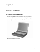
chapter 1 P RODUCT D ESCRIPTION 1.1 Computer Features and Models The Compaq Armada E700 Series of Personal Computers offers advanced modularity, an Intel Pentium II processor with 64-bit architecture, an industry-leading Accelerated Graphics Port (AGP) implementation, and extensive multimedia support. The computer provides desktop functionality and connectivity through the optional Compaq expansion base and compaq convenience base. Figure 1-1.
Models The Armada E700 models are shown in Table 1-1. The computer model designation is composed of a group of characters that define each model’s features. Table 1-1 Models and Model Naming Convention Compaq Armada E700 Series of Personal Computers Key 7 0 0 6 400 T14 14.
Features The computer has the following standard features: ■ Intel Mobile 400-MHz Pentium II processor with 64-bit architecture, MMX technology, and 512-Kbyte, level-2 cache memory ■ Industry-leading portable computer AGP implementation, featuring: - 66-MHz dedicated graphics bus - frame made AGP ■ 4-MB SGRAM (synchronous graphics) ■ 128-MB of SDRAM (synchronous) on system board; expandable to 384 MB ■ Upgradable flash ROM BIOS ■ 14.
Intelligent Manageability Intelligent Manageability consists of preinstalled software tools for the computer and Compaq servers that assist in tracking, troubleshooting, protecting, and maintaining the computer. It provides the following functions: ■ Asset Management—provides detailed configuration and diagnostic information. ■ Fault Management—prevents, predicts, and alerts of impending hardware problems. ■ Security Management—protects unauthorized access to data and components.
■ Inventory information—The network administrator can retrieve information about the computer over the network by using Compaq Insight Manager or any PC management tool provided by Compaq Solution Partners.
Fault Management Alerts Alerts can be enabled, disabled, and tested, and software can be set to back up information whenever a hard drive alert occurs. ■ While the computer is connected to a network, alerts pop up on the computer display and are simultaneously reported to the network console. ■ System temperature alert—reports overheating. As the system temperature rises, this feature first adjusts fan speed and other cooling components, then displays an alert, then shuts down the system.
Configuration Management Configuration Management optimizes software upgrade and customer support procedures. Compaq provides support software to optimize the performance of the computer. This support software is accessible through a monthly CD-ROM subscription. Support software can also be downloaded from the Compaq Web site at www.compaq.com/support/ portables.
1.2 Computer Components System Memory Options The main memory subsystem supports a minimum standard 128 MB of Synchronous SDRAM, expandable to 384 MB. The minimum standard Synchronous SDRAM is integrated on the system board. The upgrade SDRAM is accomplished with memory expansion boards that are available in 32-, 64-, and 128-MB. The memory expansion slot cover is secured to the computer by a slotted Torx T-8 screw.
Power Equipment The following battery options are available: ■ Lithium ion battery pack ■ Battery Charger ■ Automobile Power Adapter/Charger and Aircraft Power Adapter Lithium Ion Battery Pack The battery pack can be used in the computer dedicated battery bay, computer MultiBay, Compaq expansion base MultiBays, and Compaq convenience base MultiBay and battery charging bay. Battery Charger The external Battery Charger has the following features: ■ Two battery charging bays ■ Charging of one battery in 1.
Mass Storage Devices The following mass storage devices are available for the computer. Table 1-3 Mass Storage Devices Device Capacity Diskette drive 3.5-inch, 1.44 MB, 720 Kbyte, and 1.2 MB (Japanese format) Hard drive 14.0 and 10.0 GB (also available as an option) CD-ROM drive 24-Speed Max (available as an option) DVD-ROM 4.7 GB SuperDIsk LS-120 drive 120 MB (available as an option) External diskette drive 3.5-inch, 1.44 MB Diskette Drive The computer uses a 3.
1.3 Computer External Components The external components on the display and left side of the computer are shown in Figure 1-2 and described in Table 1-4. Figure 1-2. Display and Left Side Components Table 1-4 Display and Left Side Components Item Component Function 1 2 Fan Provides airflow exhaust. Video out jack Connects a television, VCR, camcorder,overhead projector, or video capture card.
The external components on the front panel of the computer are shown in Figure 1-3 and are described in Table 1-5. Figure 1-3. Front Panel Components Table 1-5 Front Panel Components Item Component Function 1 2 Mono microphone jack Connects mono microphone, disabling the built-in microphone. Stereo speaker/headphone jack Connects external stereo speakers, headphones, or headset. This jack is driven by an amplifier and has volume control.
The external components on the right side of the computer are shown in Figure 1-4 and are described in Table 1-6. Figure 1-4. Right Side Components Table 1-6 Right Side Components Item Component Function 1 2 Audio bass port Enhances sound. 3 RJ-11 jack (internal modem models only) Connects the modem cable to an internal modem. NOTE: A modem cable is included with internal modem models.
The external components on the rear panel of the computer are shown in Figure 1-5 and described in Table 1-7. Figure 1-5. Rear Panel Components Table 1-7 Rear Panel Components Item 1 Component Function Infrared port Provides wireless communication between the computer and another infrared-equipped device using an infrared beam. Connects USB devices, such as cameras for video conferencing, or hubs which connect multiple USB devices. This connector is a powered hub.
Computer keyboard components are shown in Figure 1-6 and described in Table 1-8. Figure 1-6.
Additional computer keyboard components are shown in Figure 1-7 and described in Table 1-9. Figure 1-7. Keyboard Components (continued) Table 1-9 Keyboard Components (continued) Item 1 2 3 4 5 6 7 8 9 10 11 12 13 Component Page up key Page down key Embedded numeric keypad Cursor-control keys Control key Function Moves image to previous screen. Moves image to following screen. Converts keys to numeric keypad. Move the cursor around the screen.
The external components on the bottom of the computer are shown in Figure 1-8 and are described in Table 1-10. Figure 1-8. Bottom Components Table 1-10 Bottom Components Item Component Function 1 Tilt feet latches Release the tilt filt. NOTE: To close the tilt feet, press the feet against the bottom of the computer. 2 3 Tilt feet Tilt the computer for ease of use. Memory expansion compartment cover Covers the memory expansion compartment.
1.4 Design Overview This section presents a design overview of key parts and features of the computer. For assembly/disassembly instructions for the parts described in this section, refer to Chapter 5. System Board The system board provides the following device connections: ■ ■ ■ ■ ■ ■ ■ ■ ■ ■ Memory expansion board MultiBay device Hard drive Display Keyboard/EasyPoint IV pointing device or touchpad Audio Pentium II processor Fan PC Cards Modem The computer is equipped with a 3.
chapter 2 T ROUBLESHOOTING Follow these basic steps when beginning the troubleshooting process: 1. 2. 3. 4. Complete the preliminary steps listed in Section 2.1. Run the Power-On Self-Test (POST) as described in Section 2.3. Run Computer Setup as described in Section 2.5. If you are unable to run POST or if the problem persists after running POST, perform the recommended actions described in the diagnostic tables in Section 2.5.
2.1 Preliminary Steps IMPORTANT: Use AC power when running POST or Computer Setup. A low battery condition could initiate Hibernation and interrupt the test. Before running POST, complete the following steps: 1. Obtain established passwords. If you must clear the passwords, go to Section 2.2. 2. Ensure that the hard drive is installed in the computer. 3. Ensure that the battery pack is installed in the computer and the power cord is connected to the computer and plugged into an AC power source. 4.
2.2 Clearing Passwords 1. 2. 3. 4. 5. 6. 7. 8. 9. Turn off the computer. Disconnect the AC Adapter (refer to Section 5.3). Remove the battery pack (Section 5.6). Disconnect and remove the Real Time Clock (RTC) battery (Section 5.11). Wait five minutes. Reconnect the RTC battery. Install the keyboard deck and keyboard assembly. Reconnect the AC Adapter. Do not reinstall the battery pack yet. Turn on the computer. NOTE: Remember to set the date and time the next time the computer is turned on. 2.
2.4 POST Error Messages If the system is not functioning well enough to run POST, or if the display is not functioning well enough to show POST error messages, refer to the Troubleshooting tables in Section 2.6. If POST detects an error, one of the following events occurs: ■ A message with the prefix "WARNING" appears, informing you where the error occurred. The system pauses until you press F1 to continue. ■ A message with the prefix "FATAL" appears, informing you where the error occurred.
Table 2-1 Continued Hard disk controller error Keyboard controller failure Keyboard failure No interrupts from Timer 0 ROM at xxxx (LENGTH yyyy) with nonzero checksum (zz) Time/Date corrupt - run SCU Hard disk xx failure (or error) The hard drive controller failed to respond to the reset command. The keyboard failed the selftest command. The keyboard failed to respond to the RESET ID command. The periodic timer interrupt is not occurring. An illegal adapter ROM was located at the specified address.
Table 2-3 Fatal Error Beep Codes Beep Code Beep Sequence Description Recommended Action 0 S-S-S-P-S-S-L-P Replace system board. 1 2 3 4 5 6 7 8 S-S-S-P-S-L-S-P S-S-S-P-S-L-L-P S-S-S-P-L-S-S-P S-S-S-P-L-S-L-P S-S-S-P-L-L-S-P S-S-S-P-L-L-L-P S-S-L-P-S-S-S-P S-S-L-P-S-S-L-P The DMA page registers are faulty. The refresh circuitry is faulty. The ROM checksum is incorrect. The CMOS RAM test failed. The DMA controller is faulty. The interrupt controller failed. The keyboard controller failed.
Selecting Computer Setup or Compaq Diagnostics for Windows The computer features two system management utilities: ■ Computer Setup is a system information and configuration utility that can be used even when your operating system is not working or will not load. It includes custom settings that are not available in Windows. To configure a device in Windows NT 4.0, you must use Computer Setup.
File Menu Begin here System information To do this ■ View identification information about the computer, docking base, and battery packs. ■ View specification information about the processor, memory and cache size, and ROM date and family. Save to floppy Restore from floppy Restore defaults Ignore changes and exit Save changes and exit Save system configuration to a diskette. Restore system configuration from a diskette.
Advanced Menu Begin here To do this Language (or press F2) Boot Options Change the Computer Setup language. Enable/disable n QuickBoot, which starts the computer more quickly by eliminating some startup tests. (If you suspect a memory failure and want to test memory automatically during startup, you may want to disable QuickBoot.) n MultiBoot, which enables you to set a startup sequence that can include any drives in the system. Device Options ■ Enable/disable the embedded numeric keypad at startup.
Removing a Hard Drive from the MultiBay Before removing a hard drive, back up all information on the hard drive. 1. Save all work, exit all applications, and shut down the computer. 2. Tilt the computer at an angle 1 so the bottom of the computer is accessible (Figure 5-17). 3. If a 12.7-mm Armada MultiBay hard drive adapter is being removed from the top MultiBay, slide the rear MultiBay release latch 2 toward the front of the computer. 4.
Inserting a Hard Drive into the MultiBay If you are moving a hard drive from the hard drive bay to the MultiBay, remove the hard drive from the hard drive tray. Refer to the “Removing a Hard Drive from the Hard Drive Bay” section in this chapter for more information. A 17-mm hard drive must be inserted into a Dual-MultiBay Hard Drive Adapter before being inserted into the computer MultiBay. A 12.
Figure 5-19. Inserting a 12.7-mm Hard Drive into a 12.7-mm Armada MultiBay Hard Drive Adapter 5. Release the slide tab. 6. Slide the hard drive assembly into the MultiBay with the bezel facing out.
5.7 MultiBay Devices Removing MultiBay Devices 1. Save all work, exit all applications, and shut down the computer. 2. Remove the media (diskettes, CD-ROMs, etc.) from the drive. Ensure that the CD tray is closed. 3. Tilt the computer at an angle 1 so the bottom of the computer is accessible (Figure 5-20). 4. To remove a device from the top MultiBay, slide the rear MultiBay release latch toward the front of the computer 2 . 5.
Inserting MultiBay Devices 1. Save all work, exit all applications, and turn off the computer. 2. Remove the media (diskettes, CD-ROM’s, etc.) from the drive to be inserted in the MultiBay. Ensure that the CD tray is closed. 3. With the bezel facing out, slide the drive into the MultiBay until it clicks into place (Figure 5-21). Figure 5-21.
5.8 PC Cards The procedure for removing PC Cards varies with the operating system being used and with the kind of PC Card being removed. If Windows 95/98 is running: ■ A PC Card can be removed while the computer is on or off. ■ The PC Card icon appears in the system tray on the Windows taskbar only while a PC Card is inserted. If Windows NT is running: ■ Some PC Cards, such as modem, ATA, flash, and SRAM cards, can be removed while the computer is on.
Removing a PC Card 1. Prepare the computer for PC Card removal. If Windows 95 or 98 is running and the computer is turned on, you must stop the PC Card before removing it. - Select the PC Card icon on the taskbar, - Select the PC Card to be stopped. A message displays when the PC Card can be safely removed. If Windows NT 4.0 with CardWare from Compaq is running and the computer is turned on, you must turn off the computer before removing some PC Cards.
Inserting a PC Card CAUTION: To prevent damage to the PC Card connectors, use minimal pressure when inserting a PC Card into a PC Card slot. 1. With the PC Card connector facing the computer and the label facing up 1 , align the edges of the card with the rails 2 in the PC Card slot (Figure 5-23). 2. Push the PC Card into the PC Card slot until the connector is seated. Figure 5-23. Inserting a PC Card 3. If Windows NT 4.
5.9 Memory Expansion Removing the Memory Expansion Compartment Cover The memory expansion compartment is located on the bottom of the computer. Either one or two memory expansion boards can be installed at a time. ! WARNING: Failure to unplug the power cord and remove the battery pack before installing a memory expansion board can damage the equipment and expose you to the risk of electrical shock. CAUTION: Electrostatic discharge (ESD) can damage electronic components.
4. Remove the screw that secures the memory expansion compartment cover to the computer 1 (Figure 5-24). NOTE: If the computer was shipped with a preinstalled memory expansion board, the cover is attached with a tamper-resistant Torx T-10 memory security screw. Use the Torx T-10 screwdriver included with the computer to remove and reinsert this screw. If the computer was not shipped with preinstalled memory expansion boards, the cover is attached with a standard Torx T-8 screw.
Removing a Memory Expansion Board 1. Lift and hold back the memory insulator 1 . The insulator is not removable (Figure 5-25). 2. Spread the retaining tabs apart 2 . The memory expansion board tilts upward. 3. Lift the edge of the memory expansion board and slide it gently out of the memory expansion slot at a 45-degree angle 3 . Figure 5-25. Removing a Memory Expansion Board 4. Place the memory expansion board in an electrostatic-safe container. 5.
Installing a Memory Expansion Board All memory expansion boards are asymmetrically keyed (notched) to ensure correct positioning. Memory expansion boards can be used in either memory expansion slot. 1. Insert the memory expansion board into an empty memory expansion slot at a 45-degree angle 1 (Figure 5-26). 2. Push the board into place until it is seated. 3. Push the memory expansion board down 2 until the board is seated in the plastic retention clips. Figure 5-26. Inserting a Memory Expansion Board 4.
Installing the Memory Expansion Compartment Cover 1. Reset the memory insulator 1 over the installed memory expansion board(s), ensuring that all edges of the memory insulator are tucked inside the memory expansion compartment (Figure 5-27). 2. Replace the memory expansion compartment cover 2 by placing it flush over the memory expansion compartment, then sliding it to the right 3 until it is seated. 3.
5.10 Keyboard Assembly The Armada E700 Series of Personal Computers can be equipped with a keyboard with either a EasyPoint IV pointing device or a touchpad. The removal procedures are the same for both keyboards. The keyboard assembly consists of the keyboard and the pointing device or touchpad, and is spared as a unit. This assembly must be removed to gain access to the interior components of the computer. 1. Prepare the computer for disassembly (Section 5.3). 2. Remove all battery packs (Section 5.5). 3.
8. Slide the four keyboard latches toward the front of the computer 1 (Figure 5-29). 9. Lift the back edge of the keyboard up and swing it forward 2 . Figure 5-29.
8. Release the Zero Insertion Force (ZIF) connector to which the keyboard cable is connected 1 . Disconnect the keyboard cable 2 (Figure 5-30). 9. Release the ZIF connector to which the pointing device cable is connected (EasyPoint IV pointing device keyboards only). 10. Disconnect the pointing device cable 4 . Figure 5-30.
11. Remove the keyboard assembly (Figure 5-31). Figure 5-31. Removing the Keyboard Assembly Reverse the above procedure to install the keyboard assembly. 5.11 CPU Cover There are two CPU covers used with the Armada E700 Series of Personal Computers: one cover accommodates the EasyPoint IV-equipped keyboard; the other cover accommodates the keyboard with the touchpad. The disassembly procedures for both CPU covers are identical.
7. Remove the eight screws from the bottom of the computer (Figure 5-32). CAUTION: The screw removed from the circled screwhole is shorter than the other seven screws. Make sure this screw is installed in the proper location when replacing the keyboard assembly. Failure to follow this caution can result in damage to the computer. Figure 5-32. Removing the CPU Cover Screws 8. Turn the computer top side up with the front of the computer facing forward. 9. Open the computer as far as it will open.
10. Release the ZIF connector to which the pick button cable is connected (Figure 5-33). 11. Disconnect the pick button cable 12. Disconnect the TouchPad cable 3 1 2. from the system board (TouchPad models only). 13. Disconnect the left and right speaker cables 4 from the audio board. Figure 5-33.
14. Lift the back edge of the CPU cover and swing it forward to remove it (Figure 5-34). Figure 5-34. Removing the CPU Cover Reverse the above procedure to install the CPU cover. 5.12 Power Supply 1. Prepare the computer for disassembly (Section 5.3). 2. Remove all battery packs (Section 5.5). 3. Remove all hard drives (Section 5.6). 4. Remove the keyboard assembly (Section 5.10). 5. Remove the CPU cover (Section 5.11). 6. Position the computer so the rear panel faces forward.
7. Remove the two screws that secure the power supply to the I/O bracket (Figure 5-35). Figure 5-35. Removing the Power Supply Screws. 8. Position the computer so the front faces forward. 9. Open the computer.
10. Disconnect the power supply cable 1 from the system board (Figure 5-36). 11. Remove the screw that secures the power supply to the system board 2 . Figure 5-36.
12. Lift up on the front of the power supply and swing it up and away until it clears the computer (Figure 5-37). Figure 5-37. Removing the Power Supply Reverse the above procedure to install the power supply. CAUTION: Make sure the fan cable is not pinched when installing the power supply. Failure to follow this caution can result in damage to the fan and power supply.
5.13 Fan Assembly 1. Prepare the computer for disassembly (Section 5.3). 2. Remove all battery packs (Section 5.5). 3. Remove all hard drives (Section 5.6). 4. Remove the keyboard assembly (Section 5.10). 5. Remove the CPU cover (Section 5.11). 6. Disconnect the cable (Figure 5-38). 1 connecting the fan assembly to the system board 7. Release the fan assembly from the brackets by pulling the brackets apart. 8. Lift the fan assembly out of the computer 2 that secure either side of the assembly 3.
5.14 Audio Board 1. Prepare the computer for disassembly (Section 5.3). 2. Remove all battery packs (Section 5.5). 3. Remove all hard drives (Section 5.6). 4. Remove the keyboard assembly (Section 5.10). 5. Remove the CPU cover (Section 5.11). 6. Remove the screw 1 that secures the audio board to the standoff mounted on the system board. (Figure 5-39). 7. Partially lift up on the rear/right edge of the audio board 2 to disconnect it from the system board. Hold the board slightly above the base assembly. 8.
5.15 Lithium Disk Cell Battery 1. Prepare the computer for disassembly (Section 5.3). 2. Remove all battery packs (Section 5.5). 3. Remove all hard drives (Section 5.6). 4. Remove the keyboard assembly (Section 5.10). 5. Remove the CPU cover (Section 5.11). 6. Remove the audio board (Section 5.14). 7. Remove the lithium disk cell battery from the bottom of the audio board (Figure 5-40). Figure 5-40.
5.16 Auxiliary Battery NOTE: Before removing the auxiliary battery, make note of the routing of the auxiliary battery cable. 1. Prepare the computer for disassembly (Section 5.3). 2. Remove all battery packs (Section 5.5). 3. Remove all hard drives (Section 5.6). 4. Remove the keyboard assembly (Section 5.10). 5. Remove the CPU cover (Section 5.11). 6. Remove the audio board. 7. Disconnect the auxiliary battery cable 1 from the system board (Figure 5-41). 8.
5.17 Mini PCI Riser Board The mini PCI riser board is used to connect a modem, network interface card (NIC), or combo card to the computer. 1. Prepare the computer for disassembly (Section 5.3). 2. Remove all battery packs (Section 5.5). 3. 4. 5. 6. Remove all hard drives (Section 5.6). Remove the keyboard assembly (Section 5.10). Remove the CPU cover (Section 5.11). Remove the screw that secures the mini PCI riser board to the base assembly 1 (Figure 5-42). 7.
Installing a Modem, LAN, or Combo Card 1. Prepare the computer for disassembly (Section 5.3). 2. Remove all battery packs (Section 5.5). 3. 4. 5. 6. Remove all hard drives (Section 5.6). Remove the keyboard assembly (Section 5.10). Remove the CPU cover (Section 5.11). Remove the three screws from the mini PCI riser board (Figure 5-43). Figure 5-43.
7. Connect the appropriate cable(s) from the RJ11 modem/RJ45 NIC connector assembly 1 to the connectors on the modem/combo card (Figure 5-44). 8. Connect the modem/combo card to the mini PCI riser board 2 . 9. Install the three screws to secure the modem/combo board to the mini PCI riser board 3 . Figure 5-44.
5.18 USB Board 1. Prepare the computer for disassembly (Section 5.3). 2. Remove all battery packs (Section 5.5). 3. 4. 5. 6. 7. Remove all hard drives (Section 5.6). Remove the keyboard assembly (Section 5.10). Remove the CPU cover (Section 5.11). Position the computer so the rear panel faces forward. Remove the two screws that secure the USB assembly to the I/O bracket (Figure 5-45). Figure 5-45. Removing the USB Board Screws 8. Position the computer so the front faces forward. 9. Open the computer.
10. Lift the USB assembly straight up (Figure 5-46). 1 to disconnect it from the system board 11. Tilt the USB assembly toward the front of the computer and remove it 2 . Figure 5-46. Removing the USB Board Reverse the above procedure to install the USB board.
5.19 Display Assembly 1. Prepare the computer for disassembly (Section 5.3). 2. Remove all battery packs (Section 5.5). 3. 4. 5. 6. 7. Remove all hard drives (Section 5.6). Remove the keyboard assembly (Section 5.10). Remove the CPU cover (Section 5.11). Position the computer so the rear panel faces forward. Remove the four screws that secure the display assembly clutches to the base assembly (Figure 5-47). Figure 5-47. Removing the Display Assembly Screws 8.
10. Disconnect the display video cable 1 11. Disconnect the display ground cable from the system board (Figure 5-48). 2 from the clip in the base assembly. Figure 5-48.
12. Lift the display assembly straight up from the computer (Figure 5-49). Figure 5-49. Removing the Display Assembly Reverse the above procedure to install the display assembly.
5.20 System Board NOTE: Make sure the PC Card release buttons are in the “in” position before removing or installing the system board. 1. Prepare the computer for disassembly (Section 5.3). 2. Remove all battery packs (Section 5.5). 3. 4. 5. 6. 7. 8. 9. Remove all hard drives (Section 5.6). Remove all MultiBay devices (Section 5.7). Remove all PC Cards (Section 5.8). Remove the keyboard assembly (Section 5.10). Remove the CPU cover (Section 5.11). Remove the power supply (Section 5.12).
16. Remove the two screws that secure the display ground clip assembly above the keyboard connector 2 (Figure 5-50). 1 and the screw Figure 5-50.
17. Remove the six screwlocks 1 and the two bushing guides 2 Figure 5-51. Removing the System Board Screwlocks and Bushing Guides 5-56 Remove and Replacement Procedures (Figure 5-51).
18. Position the computer so the front faces forward. 19. Remove the display ground clip assembly (Figure 5-52). Figure 5-52.
20. Remove the six screws that secure the heat sink to the system board 21. Remove the heat sink 2. Figure 5-53. Removing the Heat Sink Screws 5-58 Remove and Replacement Procedures 1 (Figure 5-53).
22. Install the two short screws removed in Step 20 into the upper/left and lower/right holes on the processor board (Figure 5-54). These screws are temporarily used to secure the processor board and processor spacers to the system board. Figure 5-54.
23. Lift the MultiBay release lever 1 off the standby on which it rests and swing it forward and to the right 2 (Figure 5-55). Figure 5-55.
24. Remove the five screws 1 and the standoff base assembly (Figure 5-56). 2 that secure the system board to the 25. Slide and hold the battery pack release lever toward the front of the computer. 26. Lift the front edge of the system board 3 . When the front edge of the system board clears the base assembly, lift the board straight up and out of the base assembly 4 . Figure 5-56. Removing the System Board Reverse the above procedure to install the system board.
NOTE: When removing the system board, make sure the expansion connector shield and processor mount bracket 2 are not dislodged (Figure 5-57). Figure 5-57.
chapter 6 S PECIFICATIONS This chapter provides physical and performance specifications for the Armada E700 Personal Computer. 6.
6.2 Display Table 6-2 14.1-inch XGA, CTFT Display Dimensions Height Width Diagonal Number of Colors Contrast Ratio Brightness Pixel Resolution Pitch Format Configuration Backlight Character Display Total Power Consumption 6-2 Specifications U.S. Metric 11.25 in 8.44 in 14.10 in 256, 32K, 64K, 16M 150:1 125 nits 28.57 cm 21.43 cm 35.71 cm 125 CD/M2 0.279 × 0.279 mm 1024 × 768 RGB Stripe Edge Lit, bottom 80 × 25 4.9 W / Inverter (max) 2.
6.3 Hard Drive Table 6-3 Hard Drive User capacity per drive (refer to note below) Drive type Drive height (with drive frame, in mm) 2.
6.4 Diskette Drive Table 6-4 Diskette Drive Diskette Size High Density Low Density 3.5 inch 1.44 MB/1.2 MB 720 KB Light Height Bytes per Sector Sectors per Track Hight Density Low Density Tracks per Side High Density Low Density Read/Write Heads Average Seek Times Track-to-Track (high/low) Average (high/low) Settling Time Latency Average None 0.59 in (15 mm) 512 6-4 Specifications 18 (1.44 MB)/15 (1.2 MB) 9 80 (1.44 MB)/80 (1.
6.
6.
6.7 LS-120 Drive Table 6-7 LS-120 Drive 1.68 MB DMF 1.44 MB 1.2 MB 1.
6.8 Battery Pack Table 6-8 Lithium Ion Battery Pack U.S. Dimensions Battery Bay Battery Pack Height Length Weight MultiBay Battery Pack Height Length Weight Dual-MultiBay Battery Pack Height Length Weight Energy and Environmental Requirements are the same for all battery packs. Energy Voltage 14.4 V Capacity 2.
6.
6.11 System I/O Addresses Table 6-11 System I/O Addresses I/O Address (Hex) System Function (Shipping Configuration) 000 - 00F DMA Controller no. 1 010 - 01F Unused 020 - 021 Interrupt Controller no.
Table 6-11 Continued I/O Address (Hex) System Function (Shipping Configuration) 26E - 26 National 87334 "Super IO" Controller in ArmadaStation/Armada MiniStation 278 - 27F 280 - 2AB Unused Unused 2A0 - 2A7 ArmadaStation/Armada MiniStation PC Card DMA Selection, 2F0 - 2F7 Hard Drive Reset, IDE Select, MultiBay Device Identification Unused Reserved Serial Port Unused 2F8 - 2FF Infrared port 300 - 31F 3E2 - 3E3 Network Interface in ArmadaStation/Armada MiniStation (Default; Alternate is 320, 340,
6.
appendix A C ONNECTOR P IN A SSIGNMENTS Table A-1 RJ-11 Connector Pin 1 2 3 4 5 6 7 8 1 3 5 7 2 4 6 8 Signal NC_J3A NC_J3B TIP RING NC_J3C NC_J3D Unused Unused Table A-2 Serial Connector 1 2 6 Pin 1 2 3 4 5 Signal Carrier Detect Receive Data Transmit Data Data Terminal Ready Ground 3 7 4 8 5 9 Pin 6 7 8 9 Signal Data Set Ready Ready to Send Clear to Send Ring Indicator Table A-3 Microphone Jack Connector Pin 1 2 1 Signal Audio in Ground 2 Connector Pin Assignments A-1
Table A-4 Stereo Speaker/Headphone Jack Connector Pin 1 2 1 Signal Audio out Ground 2 Table A-5 Stereo Line-in Jack Connector Pin 1 2 1 Signal Audio in Ground 2 Table A-6 Parallel Connector 13 12 25 Pin 1 2 3 4 5 6 7 8 9 10 11 12 13 Signal Strobe Data Bit 0 Data Bit 1 Data Bit 2 Data Bit 3 Data Bit 4 Data Bit 5 Data Bit 6 Data Bit 7 Acknowledge Busy Paper End Select A-2 Connector Pin Assignments 11 24 10 23 9 22 8 21 7 20 6 19 Pin 14 15 16 17 18 19 20 21 22 23 24 25 5 18 4 17 3 16 2 1
Table A-7 Docking Connector 1 31 61 91 30 60 90 120 Pin 1 2 3 4 5 6 7 8 9 10 11 12 13 14 15 16 17 18 19 20 21 22 23 24 25 26 27 28 29 30 31 32 33 Signal EBOXL AGND EBOXS1 RED AGND GREEN AGRD BLUE AGND VSYNC HSYNC DDC DAT DDC CLK GND INDEX RDATA TRK0 WDATA WGATE STEP DIR POWER ON SYS RESET GND DSKCHG +5 V (VDD) AUGND XA2/L IN XA3/R IN MID0/MIC IN AUGND XA0/L OUT XSD/MIC SN Pin 34 35 36 37 38 39 40 41 42 43 44 45 46 47 48 49 50 51 52 53 54 55 56 57 58 59 60 61 62 63 64 65 66 Signal XA1/R OUT GND GND EXPC
Table A-7 Continued Pin 67 68 69 70 71 72 73 74 75 76 77 78 79 80 81 82 83 84 85 86 87 88 89 90 91 92 93 94 95 96 97 98 99 100 101 102 103 104 Signal PDATA6 LD14 PDATA7 LD15 GND ERROR LCLK RXD1 LVREQ TXD1 LCREQ RTS1 LEN GND CTS1 LIIC CLK DTR1 LIIC DAT DSR1 EX DCD1 EX 12C DATA GND 12C CLK GND HDSEL GND WPROT EBOXS2 /GND ERDY EBOXL /GND FLUSHREQ MEMACK PS2 VCC SERIRQ PS2 CLK EXPREQ AD[29] AD[31] AD[30] AD[28] AD[26] GND AD[24] AD[22] AD[20] AD[18] Pin 105 106 107 108 109 110 111 112 113 114 115 116 117 118
Table A-7 Continued Pin 143 144 145 146 147 148 149 150 151 152 153 154 155 156 157 158 159 Signal VBATT AD[23] GND AD[21] AD[19] AD[17] GND AD[14] AD[12] AD[10] AD[08] GND AD[07] AD[05] AD[03] AD[01] GND Pin 160 161 162 163 164 165 166 167 168 169 170 171 172 173 174 175 176 Signal CBE3 CBE2 IRDY DEVSEL LOCK OERR SERR GND RSVD3 M 12C CLK M 12C DATA M RING MGND M DXTN GND M DXTP MSTRBAT Table A-8 External Keyboard/Mouse Connector Connector 6 5 4 3 KEY 2 1 Pin 1 2 3 4 5 6 Signal Keyboard/Mouse DAT
Table A-9 External Monitor Connector 5 4 10 15 Pin 1 2 3 4 5 6 7 8 Signal Red Analog Green Analog Blue Analog NC Ground Ground Ground Ground A-6 Connector Pin Assignments 3 14 2 8 KEY 13 1 7 12 Pin 9 10 11 12 13 14 15 6 11 Signal NC Ground NC DDC Data Horizontal Sync Vertical Sync DDC Clock
appendix B P OWER C ORD S ET R EQUIREMENTS 3-Conductor Power Cord Set The wide range input feature of the Armada E700 Series of Personal Computers permits it to operate from any line voltage from 100 to 120 or 220 to 240 volts AC. The power cord set received with the computer meets the requirements for use in the country where the equipment is purchased. Power cord sets for use in other countries must meet the requirements of the country where the computer is used.
Country-Specific Requirements 3-Conductor Power Cord Set Requirements—By Country Country Accredited Agency Applicable Note Numbers Australia EANSW 1 Austria OVE 1 Belgium CEBC 1 Canada CSA 2 Denmark DEMKO 1 Finland FIMKO 1 France UTE 1 Germany VDE 1 Italy IMQ 1 Japan JIS 3 The Netherlands KEMA 1 Norway NEMKO 1 Sweden SEMKO 1 Switzerland SEV 1 United Kingdom BSI 1 United States UL 2 Notes 1. The flexible cord must be Type HO5VV-F, 3-conductor, 1.
Index A Aircraft Power Adapter, 1-9 cable spare part number, 3-6 Asset Management, 1-4 asset tag number, 1-4 audio bass port illustrated, 1-11, 1-13 board removing, 5-43 spare part number, 3-3 Automobile Power Adapter/Charger, 1-9 cable spare part number, 3-6 auxiliary battery illustrated, 3-2 spare part number, 3-3 B base assembly illustrated, 3-2 spare part number, 3-3 battery auxiliary removing, 5-45 bay illustrated, 1-12 charger, 1-9 disk cell removing, 5-44 spare part number, 3-3 pack 8 cell spare par
display release latch illustrated, 1-11 specifications, 6-2 switch illustrated, 1-15 display assembly illustrated, 3-2 removing, 5-51 spare part number, 3-3 docking connector illustrated, 1-14 pinout, A-3 restraint latch recess illustrated, 1-17 DVD-ROM drive spare part number, 3-5 specifications, 6-6 E EasyPoint IV pointing stick illustrated, 1-15 electrostatic damage preventing, 4-3 discharge typical voltage levels, 4-6 embedded numeric keypad illustrated, 1-16 external monitor connector illustrated, 1-1
messages fatal error, 2-5 warning, 2-4 microphone illustrated, 1-11 jack illustrated, 1-12 pinout, A-1 Microsoft logo key illustrated, 1-15 mini PCI riser board removing, 5-46 spare part number, 3-3 miscellaneous spare part numbers, 3-6 Miscellaneous Plastics/Hardware Kit components, 3-4 illustrated, 3-4 spare part number, 3-3, 3-4 Miscellaneous Screw Kit spare part number, 3-6 models computer, 1-2 modem board illustrated, 3-2 card installing, 5-47 monitor connector pinout, A-6 mouse buttons illustrated, 1-
Security Management, 1-6 serial connector illustrated, 1-14 pinout, A-1 serial number, viii location, 1-17, 3-1, 5-1 service considerations, 4-1 setup computer, 2-7 software Info Messenger, 2-12 updating, 2-12 specifications battery pack, 6-8 CD-ROM drive 24X Max, 6-5 diskette drive, 6-4 display, 6-2 DMA, 6-8 DVD-ROM drive, 6-6 hard drive, 6-3 I/O addresses, 6-10 interrupts, 6-9 LS-120 SuperDisc drive, 6-7 memory map, 6-12 stereo line-in jack illustrated, 1-12 pinout, A-2 speaker jack illustrated, 1-12 pino