
Installation guide


Procedure 11
Tools required: small and large flathead screwdrivers
1.
Ground yourself to the cabinet with the antistatic wrist strap.
2.
Remove each processor and memory module by pushing the handles of the
module in toward the module end plate and to the left, releasing them from the
stops. Grasp the end plate and slide the module out of the card cage. See
➋ in
Figure 4. Place each module in an antistatic bag as it is removed from the card
cage. Remove any filler modules.
3.
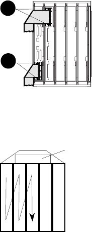
At the rear of the cabinet, use the small flathead screwdriver to disconnect all
I/O cables from KFTIA and KFTHA modules (see Figure 5). Label each hose
with the connector number from which it is being detached. Figure 6 shows the
connector (C0, C1, etc.) numbering scheme. The KFTHA has four hose
connectors, numbered in increasing order from top to bottom.
4.
Remove the KFTIA and KFTHA modules using the procedure in step 2.
Figure 5 Removing I/O Cables
BX-0756B-96
3
3
Figure 6 Hose Numbering Scheme for KFTHA
8
C0
TLSB node
7 6 5 4
C3
C4
Centerplane
BX-0164A-96
C7
C8
C11