
Technical information

FRU Removal and Replacement 8-17
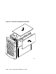
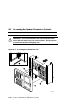
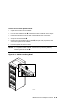
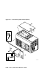
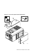
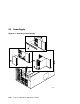
Figure 8–7 and Figure 8–8 show the location and removal of covers on the tower
and pedestal/rackmount systems, respectively. The numbers in the illustrations
correspond to the following:
➊
3mm Allen captive quarter-turn screw that secures each cover.
➋ Spring-loaded ring that releases cover. Each cover has a ring.
➌
Fan area cover. This area contains the 6.75-in main system fan and a
redundant fan.
➍
System card cage cover. This area contains CPUs, memory DIMMs,
MMBs, and system motherboard. To remove the system card cage cover,
you must first remove the fan area cover
➌. An interlock switch shuts the
system down when you remove the system card cage cover.
➎
PCI card cage cover. This area contains PCI cards, the PCI backplane, and
four fans.