
Specifications

Operation 2-23
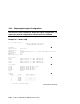
➎
PCI bus information.
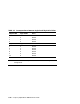
The “Slot” column lists the logical slots seen by the system. These are not
the physical slots into which devices are installed. See Table 2–1 for the
correspondence between logical slots and physical slots.
The NCR 53C896 on Hose 0, Bus 0 is a dual-channel Ultra2 SCSI
multifunction controller. Two controllers reside on the same chip. They
are shown as 2/0 and 2/1. The first number is the logical slot, and the
second is the function.
The Acer Labs bridge chip, which is located in PCI logical slot 7, has two
built-in IDE controllers. The CD-ROM is on the first controller.
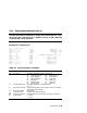
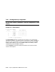
NOTE: The naming of devices (for example,dqa.0.0.15.0) follows the
conventions described in Table 2–2.
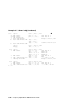
In Example 2–7, the following devices are present:
Hose 0, Bus 0, PCI
Slot 2/0 SCSI controller
Slot 2/1 SCSI controller
Slot 4 VGA controller
Slot 7 PCI to ISA bridge chip
Slot 15 IDE controller and CD-ROM drive
Slot 19 Universal serial bus (USB) controller
Hose 0, Bus 1, ISA
Diskette drive
Hose 1, Bus 0, PCI
Slot 1 SCSI controller and drives
Slot 3 SCSI controller and drives
Slot 4 Ethernet controller
Slot 6 PCI-to-PCI bridge chip to Bus 2
Hose 1, Bus 2, PCI
Slot 0 SCSI controller
Slot 1 SCSI controller
Slot 2 Ethernet controller
Continued on next page