
Specifications


Configuring and Installing Components 5-39
WARNING: To prevent injury, access is limited to persons who
have appropriate technical training and experience. Such
persons are expected to understand the hazards of working
within this equipment and take measures to minimize danger to
themselves or others.
WARNING: To prevent injury, unplug the power
cord from each power supply before installing
components.
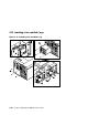
1.
Remove the cover to the PCI card cage.
2.
Install the SCSI controller
➊ in the PCI backplane.
3.
Unscrew the disk cage filler plate
➋ and set aside the four screws.
4.
Slide the cage
➌ into the system chassis part way.
5.
Pull out the two fans blocking access to the cabling.
6.
Connect the power source cable
➍ to the storage backplane.
7.
Plug one end of the 68-conductor SCSI cable
➎ (17-04867-01) into the SCSI
controller
➊.
8.
Route the SCSI cable though the accessible opening
➏ in the PCI cage and
plug it into the J3 (IN) connector
➐ on the back of the storage backplane.
9.
Plug one end of the 10-pin storage subsystem management cable
(17-03971-08) into the J2 connector
➑ on the back of the newly installed
disk cage, and plug the other end into J9
➒ on the other disk cage.
10.
Slide the cage the rest of the way into the system chassis and replace the
four screws set aside previously.
11.
Replace the two fans.
12.
Replace the PCI card cage cover and enclosure covers.
Continued on next page