
Specifications

Configuring and Installing Components 5-33
WARNING: To prevent fire, use only modules with current
limited outputs. See National Electrical Code NFPA 70 or Safety
of Information Technology Equipment, Including Electrical
Business Equipment EN 60 950.
V @ >240VA
WARNING: High current area. Currents exceeding
240 VA can cause burns or eye injury. Avoid
contact with parts or remove power prior to access.
WARNING: To prevent injury, unplug the power
cord from each power supply before installing
components.
NOTE: Some full-length PCI cards may have extender brackets for installing
into ISA/EISA card cages. Remove the extender brackets before
installing the card.
1.
Shut down the operating system and turn off power to the system. Unplug
the power cord from each power supply.
2.
Access the system chassis by following the instructions in Section 5.1.
Remove the cover from the PCI card cage area as described in Section 5.2.
3.
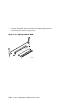
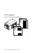
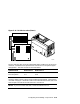
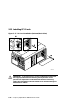
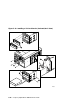
Determine the location of the PCI slot. See Figure 5–15 or Figure 5–16.
4.
Remove and discard the bulkhead filler plate
➊ from the PCI slot.
5.
Insert the card into the connector
➋.
6.
Connect cables and secure the module to the card cage with the latch
➌.
7.
Replace the PCI card cage cover and enclosure covers.
8.
Reconnect the power cords.
Continued on next page