
Specifications


Using the Remote Management Console 4-29
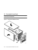
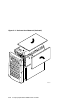
Figure 4–4 RMC Jumpers (Default Positions)
PK0211
1 2 3
1 2
J24
J25
J26
J31
J3
J2
J1
7.
Plug a power cord into one power supply, and then wait until the control
panel displays the message “System is down.”
8.
Unplug the power cord. Wait until the +5V Aux LED on the power supply
goes off before proceeding.
9.
Install jumper J25 over pins 2 and 3.
10.
Reinstall CPU1, the card cage cover and fan cover and the enclosure panels.
11.
Plug the power cord into each of the power supplies.
NOTE: After the RMC has been reset to defaults, perform the setup procedures
to enable remote dial-in and call-out alerts. See Section 4.6.5.