
User`s guide


7-10 AlphaServer DS20 User’s Guide
7.4
Installing a Memory DIMM Option
Remove the top cover and side panel to access the system board. Install a
memory option by following the procedure discussed. Figure 7–6 shows the
memory slots on the system board.
Configuration Rules
•
A memory option consists of four DIMMs all of which must be the same size.
•
Convention places the largest memory option in slots marked 0 on the system
board. See Figure 7–6.
•
Other memory options can be the same size or smaller than the first memory
option.
•
Memory options must be installed in slots designated for each bank. The first
bank goes into slots marked 0, the second bank into slots marked 1, and so on.
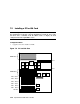
Figure 7–6 Memory Slots on System Board
CPU 0
CPU 1
C
Chip
D
Chip
D
Chip
D
Chip
D
Chip
D
Chip
D
Chip
D
Chip
D
Chip
P
Chip
P
Chip
PKW1401B-98
2
2
0
0
3
3
1
1
2
2
0
0
3
3
1
1
PCI 0 Slot 7
PCI 0 Slot 8
PCI 0 Slot 9
PCI 1 Slot 7
PCI 1 Slot 8
PCI 1 Slot 9
ISA Slot
DIMM Slots
DIMM Slots