
Specifications


4–18 Functional Description
9 March 1999 – Subject To Change
DC Power Distribution
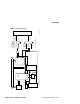
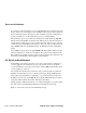
microprocessor and SROM (such as the clock). Connector J29 supports an RS-232
or RS-422 terminal connection to this port by using 1488 and 1489 line driver and
receiver components. Additional external logic is not required.
Figure 4–9 Serial ROM
4.8 DC Power Distribution
The AlphaPC 164LX derives its system power from a user-supplied PC power sup-
ply. The power supply must provide +12 V dc and -12 V dc, -5 V dc, +3 V dc, and
+5 V dc (Vdd). The dc power is supplied through power connector J3 (pc164lx.31),
as shown in Figure 4–10. Power is distributed to the board logic through dedicated
power planes within the eight-layer board structure.
Figure 4–10 shows that the +12 V dc, -12 V dc, and -5 V dc are supplied to ISA con-
nectors J30 and J31 (pc164lx.23). The +12 V dc and -12 V dc are supplied to ISA
connectors and PCI32 connectors J16 and J17 (pc164lx.20). The +12 V dc is also
supplied to the CPU fan connector J18 (pc164lx.28), auxiliary fan connectors J2 and
J19 (pc164lx.28), and to the flash ROM write-enable connector J28 (pc164lx.28).
srom_dat_h
srom_oe_l
srom_clk_h
srom_clk_l
test_srom_d_l
J29
pc164lx.3
pc164lx.26
21164
pc164lx.2
SROM
pc164lx.3
2
5
test_srom_d
pc164lx.3 FM-05952.AI4
real_srom_d
MUX