
Specifications


9 March 1999 – Subject To Change
Functional Description 4–17
Serial ROM
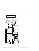
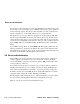
Figure 4–8 System Reset and Initialization
4.7 Serial ROM
The serial ROM code is contained in the Xilinx XC17128 serial configuration ROM.
This code is executed by the 21164 microprocessor when system power is turned on.
The serial ROM code initializes the system, then transfers control to either the Mini-
Debugger or the selected firmware, depending upon the setting of the configuration
jumper CF7.
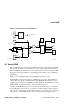
Figure 4–9 is a simplified diagram of the SROM and serial port logic.
Signal srom_oe_l selects the input to a multiplexer (pc164lx.3). The multiplexer
selects either the output of the Xilinx XC17128 SROM (real_srom_d) or a user-
supplied input through the test SROM port (test_srom_d). The multiplexer output
(srom_dat_h) provides data input to the 21164 microprocessor.
After the initial SROM code has been read into the 21164 microprocessor’s Icache,
the test SROM port can be used as a software-controlled serial port. This serial port
can be used for diagnosing system problems when the only working devices are the
microprocessor, the SROM, and the circuits needed for the direct support of the
pc164lx.28
Fan Sensor
Power Supply
Reset Switch
J18
p_dcok
+3 V
shdn_l
fan_ok_l
2
pc164lx.31
pc164lx.28
J3
J21
8
1
2
Debounce
Power
FM-05951.AI4
pc164lx.31
J3
b_dcok
sys_reset_l
dc_ok_h
rst_l
sys_reset(n)_l
To +2.5-V Regulator
System
Sense
pc164lx.32
Buffering
pc164lx.29
21174
21164
pc164lx.2
pc164lx.7
IRQ Mux
pc164lx.30
Reset
SIO
pc164lx.22
irq_reset_l
pc164lx.30