HP Compaq 6530s Notebook PC HP Compaq 6531s Notebook PC HP Compaq 6535s Notebook PC Maintenance and Service Guide
© Copyright 2008 Hewlett-Packard Development Company, L.P. AMD Athlon, AMD Sempron, and AMD Turion are trademarks of Advanced Micro Devices, Inc. Bluetooth is a trademark owned by its proprietor and used by HewlettPackard Company under license. Intel, Core, Celeron are trademarks of Intel Corporation in the United States and other countries. Microsoft, Windows, and Windows Vista are U.S. registered trademarks of Microsoft Corporation. SD Logo is a trademark of its proprietor.
Safety warning notice WARNING! To reduce the possibility of heat-related injuries or of overheating the computer, do not place the computer directly on your lap or obstruct the computer air vents. Use the computer only on a hard, flat surface. Do not allow another hard surface, such as an adjoining optional printer, or a soft surface, such as pillows or rugs or clothing, to block airflow.
iv Safety warning notice
Table of contents 1 Product description 2 External component identification Top components ................................................................................................................................... 8 Display components ............................................................................................................ 8 TouchPad ............................................................................................................................
Equipment guidelines ....................................................................... 42 Unknown user password ................................................................................................... 43 Component replacement procedures ................................................................................................. 44 Service tag ......................................................................................................................... 44 Computer feet ......
System I/O address specifications ................................................................................................... 108 System memory map specifications ................................................................................................. 110 7 Screw listing Slotted Torx ST8M2.5×7.0 screw ..................................................................................................... 111 Phillips PM2.0×3.0 screw .............................................................
10 Power cord set requirements Requirements for all countries and regions ...................................................................................... 140 Requirements for specific countries and regions ............................................................................. 141 11 Recycling Battery .............................................................................................................................................. 142 Display .........................................
1 Product description Category Description Product Name HP Compaq 6535s Notebook PC Computer models equipped with GL40 system board Computer models equipped with GM45 system board Processors Computer models equipped with RS780 system board √ HP Compaq 6531s Notebook PC HP Compaq 6530s Notebook PC Computer models equipped with PM45 system board √ √ √ ● Intel® Core™2 Duo P7370 2.0 GHz processor, 3-MB L2 cache, 1066-MHz front side bus (FSB) √ √ ● Intel Core2 Duo P8400 2.
Category Chipset Description Computer models equipped with GL40 system board ● Intel Celeron, Dual-Core T1700 1.83-GHz processor, 1-MB L2 cache, 667-MHz front side bus (FSB) √ ● AMD Turion™ X2 Ultra DualCore ZM-86 2.4-GHz processor, 35W, 2-MB L2 cache √ ● AMD Turion X2 Ultra DualCore ZM-84 2.3-GHz processor, 35W, 2-MB L2 cache √ ● AMD Turion X2 Ultra DualCore ZM-82 2.2-GHz processor, 35W, 2-MB L2 cache √ ● AMD Turion X2 Ultra DualCore ZM-80 2.
Category Description Computer models equipped with GL40 system board Computer models equipped with GM45 system board ATI-M82se discrete graphics subsystem memory with hypermemory support Panels Memory ● 128MB GDDR2 - 500 MHz (16Mx16, Qty 4) ● 256MB GDDR2 - 500 MHz (32Mx16, Qty 4) Computer models equipped with PM45 system board Computer models equipped with RS780 system board √ AMD RS780MN √ AMD UMA graphics subsystem integrated with shared video memory (dynamically allocated) √ All display
Category Hard drives Optical drives 4 Description Computer models equipped with GL40 system board Computer models equipped with GM45 system board Computer models equipped with PM45 system board Computer models equipped with RS780 system board PC2-5300, 667-MHz and PC2-6400, 800-MHz, DDR2 √ √ √ √ Supports the following configurations only in Brazil: √ √ √ √ Supports 9.5-mm (2.
Category Diskette drive Description Computer models equipped with GL40 system board Computer models equipped with GM45 system board Computer models equipped with PM45 system board Computer models equipped with RS780 system board Supports the following drives: √ √ √ √ ● DVD±RW and CD-RW Super Multi Double-Layer Combo Drive with LightScribe ● DVD/CD-RW Combo Drive ● DVD-ROM Drive ● Blu-ray Disc ROM with SuperMulti DVD±R/RW Double-Layer Combo Drive √ Supports external USB diskette drive on
Category Description Computer models equipped with GL40 system board Computer models equipped with GM45 system board Computer models equipped with PM45 system board Computer models equipped with RS780 system board Media Card Reader One ExpressCard/54 slot √ √ √ √ SD/MMC Card Reader supporting Memory Stick (MS), Memory Stick Pro (MSP), MultiMedia Card (MMC), MultiMedia Card (MMC) Plus, Secure Digital (SD) Memory Card, Secure Digital High Capacity (SDHC) Memory Card, xD-Picture Card (XD), xD-Pictu
Category Description Computer models equipped with GL40 system board Computer models equipped with GM45 system board Computer models equipped with PM45 system board Computer models equipped with RS780 system board √ √ √ √ Certified: Microsoft® WHQL √ √ √ √ Web Support: √ √ √ √ AC adapter √ √ √ √ Battery (system) √ √ √ √ Hard drive √ √ √ √ Memory module √ √ √ √ Optical drive √ √ √ √ WLAN module √ √ √ √ ● Windows Vista Business 32 (with Windows® XP Pro images
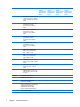
2 External component identification Top components Display components 8 Item Component Function (1) WLAN antenna locations Send and receive signals from one or more WLAN devices. These antennae are not visible from the outside of the computer. (2) Webcam light (select models only) On: The integrated camera is in use. (3) Webcam (select models only) Records audio and video and captures still photographs.
TouchPad Item Component Function (1) TouchPad* Moves the pointer and selects or activates items on the screen. (2) Left TouchPad button* Functions like the left button on an external mouse. (3) TouchPad scroll zone Scrolls up or down. (4) Right TouchPad button* Functions like the right button on an external mouse. *This table describes factory settings. View or change pointing device preferences as follows: ● In Windows Vista, select Start > Control Panel > Hardware and Sound > Mouse.
Buttons, switch, lights, and speakers Item Component Function (1) Wireless light ● On: An integrated wireless device, such as a wireless local area network (WLAN) device, the HP Broadband Wireless Module, and/or a Bluetooth device, is on. ● Off: All wireless devices are off. (2) Wireless button Turns the wireless feature on or off, but does not establish a wireless connection. NOTE: A wireless network must be set up in order to establish a wireless connection.
Item Component Function To learn more about power settings, follow these steps: ● In Windows Vista, select Start > Control Panel > System and Maintenance > Power Options. ● In Windows XP, select Start > Control Panel > Performance and Maintenance > Power Options. (5) Speakers (2) Produce sound. (6) Internal display switch Turns off the display if the display is closed while the power is on. (7) Caps lock light On: Caps lock is on.
Front components Item Component Function (1) Media Card Reader Supports the following optional digital card formats: (2) Drive light ● Memory Stick (MS) ● Memory Stick Pro (MSP) ● MultiMedia Card (MMC) ● MultiMedia Card (MMC) Plus ● Secure Digital (SD) Memory Card ● Secure Digital High Capacity (SDHC) Memory Card ● xD-Picture Card (XD) ● xD-Picture Card (XD) Type H ● xD-Picture Card (XD) Type M ● Blinking turquoise. The hard drive or optical drive is being accessed.
Item Component Function (2) Optical drive Reads optical discs and, on select models, also writes to optical discs. (3) Security cable slot Attaches an optional security cable to the computer. NOTE: The security cable is designed to act as a deterrent, but it may not prevent the computer from being mishandled or stolen.
Left-side components Item Component Function (1) RJ-11 (modem) jack Connects a modem cable. (2) Vent Enables airflow to cool internal components. NOTE: The computer fan starts up automatically to cool internal components and prevent overheating. It is normal for the internal fan to cycle on and off during routine operation. 14 (3) External monitor port Connects an external VGA monitor or projector. (4) Battery light ● Amber: A battery is charging.
Bottom components Item Component Function (1) Battery bay Holds the battery. (2) Battery release latches (2) Release the battery from the battery bay. (3) Vents (4) Enable airflow to cool internal components. NOTE: The computer fan starts up automatically to cool internal components and prevent overheating. It is normal for the internal fan to cycle on and off during routine operation. (4) Memory module compartment Contains a memory module. (5) Hard drive bay Holds the hard drive.
3 Illustrated parts catalog Service tag The service tag, affixed to the bottom of the computer, provides information that may be needed when troubleshooting system problems. The service tag provides the following information: (1) Product name: This is the product name affixed to the front of the computer. (2) Serial number (s/n): This is an alphanumeric identifier that is unique to each product.
Computer major components Item Description (1) Display assembly (include 2 WLAN antenna transceivers and cables) Spare part number For use only with HP Compaq 6535s Notebook PC models 14.1-inch, WXGA BrightView display assembly with camera 493155-001 14.
Item Description Spare part number 14.1-inch, WXGA display assembly with camera 493152-001 14.1-inch, WXGA display assembly 493151-001 For use only with HP Compaq 6530s and 6531s Notebook PC models 14.1-inch, WXGA BrightView display assembly with camera 491643-001 14.1-inch, WXGA display assembly with camera 491642-001 14.1-inch, WXGA BrightView display assembly 491641-001 14.
Item (5) Description Spare part number For use in Thailand 491653-281 For use in the United States 491653-001 Speakers For use only with HP Compaq 6535s Notebook PC models 493173-001 For use only with HP Compaq 6530s and 6531s Notebook PC models 491656-001 (6) Top cover (includes TouchPad board and cable, and TouchPad button board and cable) 491632-001 (7) Modem module cable (includes RJ-11 connector) (8) TouchPad spared with top cover (9) Plastics Kit (see Plastics Kit on page 25 for mo
Item Description Spare part number ● For use only with computer models equipped with AMD processors 497613-001 ● For use only with computer models equipped with Intel processors with UMA graphics subsystem and a GM45 system board 501354-001 ● For use only with computer models equipped with Intel processors with UMA graphics subsystem and a GL40 system board 491250-001 ● For use only with computer models equipped with Intel processors (includes 128-MB DDR2 discrete graphics system memory) 49197
Item Description Spare part number ● 493145-001 SI–40 2.
Item Description Spare part number Suriname, Swaziland, Sweden, Switzerland, Taiwan, Tajikistan, Tanzania, Togo, Tonga, Trinidad and Tobago, Tunisia, Turkey, Turkmenistan, Tuvalu, Uganda, Ukraine, the United Arab Emirates, the United Kingdom, Uruguay, Uzbekistan, Vanuatu, Venezuela, Vietnam, Yemen, Zaire, Zambia, and Zimbabwe Broadcom 4321 802.11a/b/g/n WLAN module for use only in Japan 453730-291 ● Broadcom 4322 802.
Item Description Spare part number Singapore, Slovakia, Slovenia, the Solomon Islands, Somalia, South Africa, South Korea, Spain, Sri Lanka, St. Kitts and Nevis, St. Lucia, St. Vincent and the Grenadines, Suriname, Swaziland, Sweden, Switzerland, Taiwan, Tajikistan, Tanzania, Togo, Tonga, Trinidad and Tobago, Tunisia, Turkey, Turkmenistan, Tuvalu, Uganda, Ukraine, the United Arab Emirates, the United Kingdom, Uruguay, Uzbekistan, Vanuatu, Venezuela, Vietnam, Yemen, Zaire, Zambia, and Zimbabwe Intel 802.
Item (24) Description Spare part number 160-GB, 5400-rpm 491646-001 120-GB, 7200-rpm 491645-001 120-GB, 5400-rpm 491644-001 Memory modules (PC2-5300, 667-MHz, DDR2) For use only with HP Compaq 6535s Notebook PC models 1-GB 493158-001 2-GB 493159-001 Memory modules (PC2-6400, 800-MHz, DDR2) For use only with HP Compaq 6535s Notebook PC models 1-GB 493161-001 2-GB 493162-001 Memory modules (PC2-5300, 667-MHz, DDR2) For use only with HP Compaq 6530s and 6531s Notebook PC models 1-GB 491623-0
Plastics Kit Item Description Spare part number Plastics Kit: For use only with HP Compaq 6535s Notebook PC models 493175-001 For use only with HP Compaq 6530s and 6531s Notebook PC models 491253-001 (1) ExpressCard slot bezel (2) WLAN module compartment cover (includes one captive screw, secured by a C-clip) (3) Memory module compartment cover (includes one captive screw, secured by a C-clip) (4) Hard drive bay cover (includes 2 captive screws, secured by C-clips) Plastics Kit 25
Cable Kit Item Description Spare part number Cable Kit 26 For use only with HP Compaq 6535s Notebook PC models 497616-001 For use only with HP Compaq 6530s and 6531s Notebook PC models 491662-001 (1) RJ-11 (modem) jack cable (2) USB cable (3) Bluetooth cable Chapter 3 Illustrated parts catalog
Mass storage devices Item Description (1) Optical drives (include bezel and bracket) Spare part number For use only with HP Compaq 6535s Notebook PC models DVD±RW Double-Layer Drive with LightScribe 493168-001 DVD/CD-RW Combo Drive 493167-001 DVD-ROM Drive 493166-001 For use only with HP Compaq 6530s and 6531s Notebook PC models (2) Blu-ray Disc ROM with SuperMulti DVD±R/RW Double-Layer 491652-001 DVD±RW Double-Layer Drive with LightScribe 491651-001 DVD±RW and CD-RW Combo Drive, Double-La
Item 28 Description Spare part number 120-GB, 7200-rpm 491645-001 120-GB, 5400 rpm 491644-001 Chapter 3 Illustrated parts catalog
Miscellaneous parts Description Spare part number AC adapters 65-W AC adapter 463958-001 90-W slimline AC adapter (for use only with HP Compaq 6530s and 6531s Notebook PC models in all countries and regions except India) 463955-001 90-W slimline AC adapter (for use only with HP Compaq 6530s and 6531s Notebook PC models in India) 463956-001 Logo Kits For use only with HP Compaq 6535s Notebook PC models 493178-001 For use only with HP Compaq 6530s and 6531s Notebook PC models 491658-001 Display ha
Description 30 ● Phillips PM2.0×3.0 screw ● Phillips PM2.0×4.0 screw ● Phillips PM2.5×6.0 captive screw ● Phillips PM2.5×5.0 screw ● Phillips PM2.5×4.0 screw ● Phillips PM2.5×9.0 screw ● Phillips PM2.5×10.0 captive screw ● Phillips PM3.0×4.0 screw ● Phillips PM2.0×2.0 broadhead screw (5-mm) ● Phillips PM2.0×2.0 broadhead screw (6-mm) ● Torx T8M2.0×2.0 broadhead (9-mm) ● Slotted Torx ST8M2.5×7.0 screw ● Torx T8M2.5×6.0 screw ● Torx T8M2.5×4.
Sequential part number listing Spare part number Description 325814-001 Nylon carrying case 359118-001 USB 1.1 diskette drive 398393-002 Broadcom Bluetooth module for use in all countries and regions except Japan and Asia Pacific 441075-001 Broadcom 4311AG 802.11a/b/g WLAN module for use in Canada, the Cayman Islands, Guam, Puerto Rico, the U.S. Virgin Islands, and the United States 441075-002 Broadcom 4311AG 802.
32 Spare part number Description 453730-291 Broadcom 4321 802.11a/b/g/n WLAN module for use only in Japan 456864-001 6-cell, 47-Wh Li-ion battery (for use only with HP Compaq 6535s Notebook PC models) 459263-001 Broadcom BCM4312 802.11b/g WLAN module for use in Antigua and Barbuda, Barbados, Belize, Canada, the Cayman Islands, Guam, Puerto Rico, Trinidad and Tobago, the U.S. Virgin Islands, and the United States 459263-002 Broadcom BCM4312 802.
Spare part number Description Zealand, Nicaragua, Niger, Nigeria, Norway, Oman, Pakistan, Palau, Panama, Papua New Guinea, Paraguay, Peru, the Philippines, Poland, Portugal, the Republic of Moldova, Romania, Russia, Rwanda, Samoa, San Marino, Sao Tome and Principe, Saudi Arabia, Senegal, Serbia, the Seychelles, Sierra Leone, Singapore, Slovakia, Slovenia, the Solomon Islands, Somalia, South Africa, South Korea, Spain, Sri Lanka, St. Kitts and Nevis, St. Lucia, St.
34 Spare part number Description 491630-001 Webcam module (for use only with HP Compaq 6530s and 6531s Notebook PC models) 491631-001 Base enclosure (includes rubber feet) for use only with HP Compaq 6530s and 6531s Notebook PC models 491632-001 Top cover (includes TouchPad board and cable, and TouchPad button board and cable) 491634-001 Display inverter (includes cable) for use only with HP Compaq 6530s and 6531s Notebook PC models 491635-001 Display bezel for use only with HP Compaq 6530s and
Spare part number Description 491653-AB1 Keyboard for use in Taiwan 491653-AD1 Keyboard for use in South Korea 491654-001 Rubber Kit for use only with HP Compaq 6530s and 6531s Notebook PC models (contains 6 computer feet and 8 display bezel screw covers) 491655-001 Screw Kit for use only with HP Compaq 6530s and 6531s Notebook PC models 491656-001 Speakers for use only with HP Compaq 6530s and 6531s Notebook PC models 491657-001 6-cell, 47-Wh Li-ion battery for use only with HP Compaq 6530s an
36 Spare part number Description 493161-001 1-GB memory module (PC2-6400, 800-MHz, DDR2) for use only with HP Compaq 6535s Notebook PC models 493162-001 2-GB memory module (PC2-6400, 800-MHz, DDR2) for use only with HP Compaq 6535s Notebook PC models 493163-001 120-GB, 5400-rpm hard drive for use only with HP Compaq 6535s Notebook PC models (includes hard drive bracket) 493164-001 160-GB, 5400-rpm hard drive for use only with HP Compaq 6535s Notebook PC models (includes hard drive bracket) 493165
Spare part number Description 500324-001 320-GB, 5400-rpm hard drive for use only with HP Compaq 6535s Notebook PC models (includes hard drive bracket) 501354-001 System board (includes replacement thermal material and the ExpressCard assembly) for use only with computer models equipped with Intel processors with UMA graphics subsystem and a GM45 system board 506281-001 AMD Athlon X2 QL–62 2.
4 Removal and replacement procedures Preliminary replacement requirements Tools required You will need the following tools to complete the removal and replacement procedures: ● Flat-bladed screwdriver ● Magnetic screwdriver ● Phillips P0 and P1 screwdrivers ● Torx T8 screwdriver Service considerations The following sections include some of the considerations that you must keep in mind during disassembly and assembly procedures.
Cables and connectors CAUTION: When servicing the computer, be sure that cables are placed in their proper locations during the reassembly process. Improper cable placement can damage the computer. Cables must be handled with extreme care to avoid damage. Apply only the tension required to unseat or seat the cables during removal and insertion. Handle cables by the connector whenever possible. In all cases, avoid bending, twisting, or tearing cables.
Grounding guidelines Electrostatic discharge damage Electronic components are sensitive to electrostatic discharge (ESD). Circuitry design and structure determine the degree of sensitivity. Networks built into many integrated circuits provide some protection, but in many cases, ESD contains enough power to alter device parameters or melt silicon junctions. A discharge of static electricity from a finger or other conductor can destroy static-sensitive devices or microcircuitry.
Packaging and transporting guidelines Follow these grounding guidelines when packaging and transporting equipment: ● To avoid hand contact, transport products in static-safe tubes, bags, or boxes. ● Protect ESD-sensitive parts and assemblies with conductive or approved containers or packaging. ● Keep ESD-sensitive parts in their containers until the parts arrive at static-free workstations. ● Place items on a grounded surface before removing items from their containers.
Equipment guidelines Grounding equipment must include either a wrist strap or a foot strap at a grounded workstation. ● When seated, wear a wrist strap connected to a grounded system. Wrist straps are flexible straps with a minimum of one megohm ±10% resistance in the ground cords. To provide proper ground, wear a strap snugly against the skin at all times. On grounded mats with banana-plug connectors, use alligator clips to connect a wrist strap.
Unknown user password If the computer you are servicing has an unknown user password, follow these steps to clear the password: NOTE: These steps also clear CMOS. 1. Shut down the computer. If you are unsure whether the computer is off or in Hibernation, turn the computer on, and then shut it down through the operating system. 2. Disconnect all external devices connected to the computer. 3.
Component replacement procedures This section provides removal and replacement procedures. There are as many as 89 screws, in 15 different sizes, that must be removed, replaced, or loosened when servicing the computer. Make special note of each screw size and location during removal and replacement. Service tag The service tag, affixed to the bottom of the computer, provides information that may be needed when troubleshooting system problems.
Computer feet The computer feet are adhesive-backed rubber pads. The feet are included in the Rubber Kit, spare part numbers 497622-001 (for use only with HP Compaq 6535s Notebook PC models) and 491654-001 (for use only with HP Compaq 6530s and 6531s Notebook PC models). There are 6 rubber feet that attach to the base enclosure in the locations illustrated below.
Battery Description Spare part number 6-cell, 47-Wh Li-ion battery For use only with HP Compaq 6535s Notebook PC models 456864-001 For use only with HP Compaq 6530s and 6531s Notebook PC models 491657-001 Before disassembling the computer, follow these steps: 1. Shut down the computer. If you are unsure whether the computer is off or in Hibernation, turn the computer on, and then shut it down through the operating system. 2. Disconnect all external devices connected to the computer. 3.
Hard drive NOTE: All hard drive spare part kits include a hard drive bracket.
48 3. Lift the right side of the hard drive bay cover (2), swing it to the left, and remove the cover (3). The hard drive bay cover is included in the Plastics Kit, spare part numbers 493175-001 (for use only with HP Compaq 6535s Notebook PC models) and 491253-001 (for use only with HP Compaq 6530s and 6531s Notebook PC models). 4. Loosen the Phillips PM2.5×10.0 captive screw (1) that secures the hard drive to the computer. 5.
8. Lift the bracket (2) straight up to remove it from the hard drive. Reverse this procedure to reassemble and install the hard drive.
WLAN module Description Spare part number Broadcom 802.11a/b/g/n WLAN modules: 50 ● Broadcom 4321 802.11a/b/g/n WLAN module for use in Antigua and Barbuda, Barbados, Belize, Canada, the Cayman Islands, Guam, Puerto Rico, Trinidad and Tobago, the U.S. Virgin Islands, and the United States 453730-001 ● Broadcom 4321 802.
Description Spare part number Broadcom 802.11/b/g WLAN modules: ● Broadcom BCM4312 802.11b/g WLAN module for use in Antigua and Barbuda, Barbados, Belize, Canada, the Cayman Islands, Guam, Puerto Rico, Trinidad and Tobago, the U.S. Virgin Islands, and the United States ● 459263-002 Broadcom BCM4312 802.
Description Spare part number Sweden, Switzerland, Taiwan, Tajikistan, Tanzania, Togo, Tonga, Trinidad and Tobago, Tunisia, Turkey, Turkmenistan, Tuvalu, Uganda, the United Arab Emirates, the United Kingdom, Uruguay, Uzbekistan, Venezuela, Vietnam, Yemen, Zaire, Zambia, and Zimbabwe ● Broadcom 4311AG 802.11a/b/g WLAN module for use in Japan 441075-291 Before removing the WLAN module, follow these steps: 1. Shut down the computer.
6. Remove the WLAN module (3) by pulling the module away from the slot at an angle. NOTE: WLAN modules are designed with a notch (4) to prevent incorrect insertion into the WLAN module slot. Reverse this procedure to install the WLAN module.
Remove the memory module: 1. Loosen the Phillips PM2.5×6.0 captive screw (1) that secures the memory module compartment cover to the computer. 2. Lift the front edge of the cover (2), swing it up and back, and remove the cover (3). The memory module compartment cover is included in the Plastics Kit, spare part numbers 493175-001 (for use only with HP Compaq 6535s Notebook PC models) and 491253-001 (for use only with HP Compaq 6530s and 6531s Notebook PC models). 3.
Optical drive NOTE: All optical drive spare part kits include an optical drive bezel.
4. Remove the optical drive (3) from the computer. 5. If it is necessary to replace the optical drive bracket, position the optical drive with the rear toward you. 6. Remove the two Phillips PM2.0×3.0 screws (1) that secure the optical drive bracket to the optical drive. 7. Remove the optical drive bracket (2). Reverse this procedure to reassemble and install an optical drive.
Switch cover and keyboard Description Spare part number Switch covers (includes power button board and cable) For use only with HP Compaq 6535s Notebook PC models 497614-001 For use only with HP Compaq 6530s and 6531s Notebook PC models 491663-001 Keyboards for use in the following countries or regions: Brazil 491653-201 Taiwan 491653-AB1 Japan 491653-291 Thailand 491653-281 Latin America 491653-161 The United States 491653-001 South Korea 491653-AD1 Before removing the switch cover and
58 2. Remove the two slotted Torx ST8M2.5×7.0 screws that secure the keyboard to the computer. 3. Turn the computer display-side up, with the front toward you. 4. Open the computer as far as possible. 5. Lift the switch cover (1) straight up until it disengages from the computer, and slide it back (2) until it rests on the display assembly.
6. Release the zero insertion force (ZIF) connector to which the LED board cable is attached, disconnect the LED board cable from the system board (1), and lift the switch cover up to remove it (2) from the system board. 7. To disengage the four tabs (1) on the back of the keyboard from the switch cover, lift up the rear edge of the keyboard (2), and slide it back (3).
8. Release the swinging ZIF connector (1) to which the keyboard cable is attached, and disconnect the keyboard cable (2) from the system board. 9. Remove the keyboard. 10. Turn the switch cover over. 11. Remove the two Phillips PM2.0×2.0 broadhead screws (1) from the switch cover. 12. Remove the LED power button board (2) from the switch cover. Reverse this procedure to install the switch cover and keyboard.
Speakers Description Spare part number For use only with HP Compaq 6535s Notebook PC models 493173-001 For use only with HP Compaq 6530s and 6531s Notebook PC models 491656-001 Before removing the speakers, follow these steps: 1. Shut down the computer. If you are unsure whether the computer is off or in Hibernation, turn the computer on, and then shut it down through the operating system. 2. Disconnect all external devices connected to the computer. 3.
Display assembly NOTE: All display assembly spare part kits include 2 WLAN antenna transceivers and cables. Description Spare part number For use only with HP Compaq 6535s Notebook PC models 14.1-inch, WXGA BrightView display assembly with camera 493155-001 14.1-inch, WXGA BrightView display assembly 493154-001 14.1-inch, WXGA display assembly with camera 493152-001 14.1-inch, WXGA display assembly 493151-001 For use only with HP Compaq 6530s and 6531s Notebook PC models 14.
5. Remove the wireless antenna cables (4) from the clips and routing channels built into the top cover. Remove the display assembly: 1. Remove the following: CAUTION: The display assembly will be unsupported when the following screws are removed. To prevent damage to the display assembly, support it before removing the screws. (1) Four slotted Torx ST8M2.5×7.0 screws that secure the display assembly to the computer.
64 2. If it is necessary to replace the display bezel, display inverter, or display hinges, remove the eight rubber screw covers (1) and the eight Torx T8M2.5×6.0 screws (2) that secure the display bezel to the display assembly. The rubber screw covers are available in the Rubber Kit, spare part numbers 497622-001 (for use only with HP Compaq 6535s Notebook PC models) and 491654-001 (for use only with HP Compaq 6530s and 6531s Notebook PC models). 3.
5. If it is necessary to replace the webcam module from the display enclosure, gently pull the webcam module from the double-sided tape on the display enclosure (1) and disconnect the webcam cable from the module (2). The webcam module can be ordered by using spare part numbers 491630-001 (for use only with HP Compaq 6530s and 6531s Notebook PC models) and 493171-001 (for use only with HP Compaq 6535s Notebook PC models).
10. Remove the display panel (2). 11. Remove the four Phillips PM2.0×3.0 screws (1) that secure each display hinge to the display panel. NOTE: When removing or replacing the eight Phillips screws, be sure to remove or replace them in the same sequence as the numbering found on the display hinges (1–2–3–4). 12. Remove the display hinges (2).
14. Remove the wireless antenna (2). 15. Remove the wireless antenna cables (3) from the clips and routing channels built into the top cover. 16. If it is necessary to replace the webcam cable from the display enclosure, gently pull the webcam cables (1) from the clips and routing channels (2) built into the top cover.
Top cover Description Spare part number Top cover (includes TouchPad board and cable, and TouchPad button board and cable) 491632-001 Before removing the top cover, follow these steps: 1. Shut down the computer. If you are unsure whether the computer is off or in Hibernation, turn the computer on, and then shut it down through the operating system. 2. Disconnect all external devices connected to the computer. 3.
2. Remove the two rubber screw covers (1) and the seven slotted Torx ST8M2.5×7.0 screws (2) that secure the top cover to the computer. The rubber screw covers are available in the Rubber Kit, spare part numbers 497622-001 (for use only with HP Compaq 6535s Notebook PC models) and 491654-001 (for use only with HP Compaq 6530s and 6531s Notebook PC models). 3. Remove the three Phillips PM2.0×2.0 broadhead (5-mm) screws from the optical drive bay (1), and remove the Torx T8M2.5x4.
70 5. Remove the two slotted Torx ST8M2.5×7.0 screws from the top cover. 6. Lift the rear edge of the top cover (1) until it disengages from the base enclosure, and then tilt the top cover (2) back until the TouchPad cable is accessible. 7. Release the ZIF connector (1) to which the TouchPad cable is connected, and then disconnect the TouchPad cable from the system board (2). 8. Remove the top cover.
Reverse this procedure to install the top cover.
USB connector module 1. Disconnect the USB cable from the system board (1). 2. Lift up the USB connector and remove the cable from the front edge of the base enclosure (2). 3. Remove the long Phillips PM2.5×9.0 screw (3) and the short Torx T8M2.5×4.0 screw (4) from the system board. 4. Remove the USB connector module (5). Reverse this procedure to install the USB connector module.
Bluetooth module Description Spare part number Broadcom Bluetooth module for use in all countries and regions except Japan and Asia Pacific 398393-002 Broadcom Bluetooth module for use only in Japan and Asia Pacific 450066-001 Before removing the Bluetooth module, follow these steps: 1. Shut down the computer. If you are unsure whether the computer is off or in Hibernation, turn the computer on, and then shut it down through the operating system. 2.
4. Remove the Bluetooth module (4) from the base enclosure. Reverse this procedure to install the Bluetooth module.
RTC battery NOTE: Removing the RTC battery and leaving it uninstalled for 5 or more minutes causes all passwords and CMOS settings to be cleared. Description Spare part number RTC battery 449137-001 Before removing the RTC battery, follow these steps: 1. Shut down the computer. If you are unsure whether the computer is off or in Hibernation, turn the computer on, and then shut it down through the operating system. 2. Disconnect all external devices connected to the computer. 3.
Reverse this procedure to install the RTC battery.
Fan Description Spare part number Fan 490324-001 Before removing the fan, follow these steps: 1. Shut down the computer. If you are unsure whether the computer is off or in Hibernation, turn the computer on, and then shut it down through the operating system. 2. Disconnect all external devices connected to the computer. 3. Disconnect the power from the computer by first unplugging the power cord from the AC outlet and then unplugging the AC adapter from the computer. 4.
3. Lift the fan up (3) from the base enclosure. Reverse this procedure to install the fan. NOTE: To properly ventilate the computer, allow at least a 7.6-cm (3-inch) clearance on the left side of the computer. The computer uses an electric fan for ventilation. The fan is controlled by a temperature sensor and is designed to turn on automatically when high temperature conditions exist.
System board NOTE: All system board spare part kits include the ExpressCard assembly. NOTE: All system board spare part kits include replacement thermal material.
When replacing the system board, be sure that the following components are removed from the defective system board and installed on the replacement system board: ● Memory module (see Memory module on page 53) ● WLAN module (see WLAN module on page 50) ● Processor (see Processor on page 88) Remove the system board: 80 1. Remove the RJ-11 connector (1) from the base enclosure clip. 2. Disconnect the Bluetooth module cable (2) and the USB connector module cable (3) from the system board. 3.
6. Remove the system board (4) from the base enclosure by sliding it back. Reverse this procedure to install the system board.
Modem module Description Spare part number For use in all countries and regions except Australia and New Zealand 461749-001 For use only in Australia and New Zealand 461749-011 Before removing the modem module, follow these steps: 1. Shut down the computer. If you are unsure whether the computer is off or in Hibernation, turn the computer on, and then shut it down through the operating system. 2. Disconnect all external devices connected to the computer. 3.
4. Disconnect the modem module cable (3) . 5. Remove the modem module. Reverse this procedure to install the modem module.
Heat sink NOTE: The heat sink spare part kit includes replacement thermal material. Description Spare part number For use only with HP Compaq 6535s Notebook PC models 493174-001 For use only with HP Compaq 6531s Notebook PC models 491980-001 For use only with HP Compaq 6530s Notebook PC models 496679-001 Before removing the heat sink, follow these steps: 1. Shut down the computer.
3. Remove the heat sink (2). NOTE: The thermal material must be thoroughly cleaned from the surfaces of the heat sink (1) and (2), and the system board components (3) and (4) each time the heat sink is removed. Replacement thermal material is included with all heat sink, system board, and processor spare part kits. NOTE: Steps 4 through 6 apply only to HP Compaq 6530s Notebook PC models. See steps 1 through 3 for removing the heat sink on HP Compaq 6531s Notebook PC models.
6. Remove the heat sink (2). NOTE: The thermal material must be thoroughly cleaned from the surfaces of the heat sink (1), (2), and (3), and the system board components (4), and (5) each time the heat sink is removed. Replacement thermal material is included with all heat sink, system board, and processor spare part kits. NOTE: Steps 7 through 9 apply only to HP Compaq 6535s Notebook PC models 86 7. Turn the system board upside down, with the audio connectors toward you. 8.
9. Remove the heat sink (2). NOTE: The thermal material must be thoroughly cleaned from the surfaces of the heat sink (1) and (2), and the system board components (3) and (4) each time the heat sink is removed. Replacement thermal material is included with all heat sink, system board, and processor spare part kits. Reverse this procedure to install the heat sink.
Processor NOTE: All processor spare part kits include replacement thermal material. Description Spare part number AMD processors for use only with HP Compaq 6535s computer models Turion Ultra ZM-86 2.40-GHz processor 493150-001 Turion Ultra ZM-84 2.30-GHz processor 506283-001 Turion Ultra ZM-82 2.20-GHz processor 493149-001 Turion Ultra ZM-80 2.10-GHz processor 493148-001 Turion RM-72 2.1GHz (35W 1-MB L2 cache) 506282-001 Turion RM-70 2.00-GHz processor 493147-001 Athlon QL-60 1.
4. Remove the battery (see Battery on page 46). 5. Remove the following components: a. Hard drive (see Hard drive on page 47) b. Optical drive (see Optical drive on page 55) c. Keyboard (see Switch cover and keyboard on page 57) d. Switch cover (see Switch cover and keyboard on page 57) e. Speakers (see Speakers on page 61) f. Display assembly (see Display assembly on page 62) g. Top cover (see Top cover on page 68) h.
5. Lift the processor (2) straight up and remove it. NOTE: When you install the processor, the gold triangle (3) on the processor must be aligned with the triangle (4) embossed on the processor socket. Reverse this procedure to install the processor.
5 Computer Setup Starting Computer Setup Computer Setup is a preinstalled, ROM-based utility that can be used even when the operating system is not working or will not load. NOTE: Some of the Computer Setup menu items listed in this guide may not be supported by your computer. NOTE: An external keyboard or mouse connected to a USB port can be used with Computer Setup only if USB legacy support is enabled. To start Computer Setup, follow these steps: 1.
Using Computer Setup Navigating and selecting in Computer Setup The information and settings in Computer Setup are accessed from the File, Security, Diagnostics, and System Configuration menus. To navigate and select in Computer Setup, follow these steps: 1. Turn on or restart the computer, and then press esc while the “Press the ESC key for Startup Menu” message is displayed at the bottom of the screen.
3. Use a pointing device or the arrow keys to select File > Restore defaults. 4. Follow the on-screen instructions. 5. To save your changes and exit, click the Save icon in the lower-left corner of the screen, and then follow the on-screen instructions. – or – Use the arrow keys to select File > Save changes and exit, and then press enter. Your changes go into effect when the computer restarts. NOTE: Your password settings and security settings are not changed when you restore the factory settings.
Computer Setup menus The menu tables in this section provide an overview of Computer Setup options. NOTE: Some of the Computer Setup menu items listed in this chapter may not be supported by your computer. File menu 94 Select To do this System Information ● View identification information for the computer and the batteries in the system. ● View specification information for the processor, cache and memory size, system ROM, video revision, and keyboard controller version.
Security menu NOTE: Some of the menu items listed in this section may not be supported by your computer. Select To do this User Management (requires an administrator password) ● Create a new BIOS user account. ● View a list of ProtectTools users. Password Policy (requires an administrator password) Revise password policy criteria. Allow HP SpareKey Enrollment Enable/disable permission to enroll or reset HP SpareKey.
Select To do this System IDs Enter a user-defined computer asset tracking number and ownership tag. Setup BIOS Administrator Password Set up a BIOS administrator password. Always Prompt for HP SpareKey Enrollment Enable/disable a prompt for HP SpareKey enrollment. Diagnostics menu 96 Select To do this System Diagnostics menu ● Chapter 5 Computer Setup F1 System Information—Displays the following information: ◦ Identification information for the computer and the batteries in the system.
System Configuration menu NOTE: Some of the listed System Configuration options may not be supported by your computer. Select To do this Language Change the Computer Setup language. Boot Options ● Set a Startup Menu delay (in seconds). ● Enable/disable Custom Logo (disabled by default). ● Enable/disable Display Diagnostic URL (enabled by default). ● Enable/disable CD-ROM boot (enabled by default). ● Enable/disable SD Card boot (enabled by default).
Select Built-In Device Options Port Options (all are enabled by default) 98 Chapter 5 Computer Setup To do this ● Enable/disable secondary battery fast charge (enabled by default). ● Enable/disable HP QuickLook 2 (enabled by default). ● Enable/disable Virtualization Technology (select models only; disabled by default). ● Enable/disable TXT (Intel Trusted Execution Technology) (select models only; disabled by default). ● Enable/disable Dual-Core CPU (select models only; enabled by default).
Select To do this ● Enable/disable the parallel port. ● Enable/disable the flash media reader. ● Enable/disable the USB port. CAUTION: Disabling the USB port also disables MultiBay devices and ExpressCard devices on the advanced port replicator. ● AMT Options (all are disabled by default) Enable/disable the 1394 port. NOTE: All AMT options are disabled by default. ● Enable/disable Firmware Verbosity. ● Enable/disable AMT Setup Prompt (CTRL-P). ● Enable/disable USB Key Provisioning Support.
6 Specifications Computer specifications Metric U.S. Depth 24.64 cm 9.70 in Width 33.80 cm 13.33 in Height (front to rear) 3.07 to 3.43 cm 1.21 to 1.35 in Weight (equipped with optical drive, hard drive, and battery) 2.27 kg 5.00 lbs Dimensions Input power Operating voltage 18.5 V dc @ 4.74 A – 90 W Operating current 4.
Metric Nonoperating U.S. 1.50 g zero-to-peak, 10 Hz to 500 Hz, 0.5 oct/min sweep rate NOTE: Applicable product safety standards specify thermal limits for plastic surfaces. The computer operates well within this range of temperatures. 14.1-inch, WXGA display specifications Metric U.S. Height 27.94 cm 11.0 in Width 20.83 cm 8.2 in Diagonal 35.56 cm 14.1 in Number of colors Up to 16.
Hard drive specifications 320–GB* 250-GB* 160-GB* 120-GB* Height 9.5 mm 9.5 mm 9.5 mm 9.
DVD±RW and CD-RW Combo Drive, Double-Layer specifications Applicable disc Read: Write: CD-DA, CD+(E)G, CD-MIDI, CD-TEXT, CDROM, CD-ROM XA, MIXED MODE CD, CD-I, CD-I Bridge (Photo-CD, Video CD), Multisession CD (Photo-CD, CD-EXTRA, Portfolio, CD-R, CDRW), CD-R, CD-RW, DVD-ROM (DVD-5, DVD-9, DVD-10, DVD-18), DVD-R, DVD-RW, DVD+R, DVD+RW, DVD-RAM CD-R and CD-RW Access time CD DVD Random < 175 ms < 230 ms Cache buffer 2 MB DVD+R, DVD+RW, DVD-R, DVDRW, DVD-RAM Data transfer rate 24X CD-ROM 3,600 K
DVD/CD-RW Combo Drive specifications Applicable disc Read: Write: CD-DA, CD+(E)G, CD-MIDI, CD-TEXT, CDROM, CD-ROM XA, MIXED MODE CD, CD-I, CD-I Bridge (Photo-CD, Video CD), Multisession CD (Photo-CD, CD-EXTRA, Portfolio, CD-R, CDRW), CD-R, CD-RW, DVD-ROM (DVD-5, DVD-9, DVD-10, DVD-18), DVD-R, DVD-RW, DVD+R, DVD+RW, DVD-RAM CD-R and CD-RW Access time CD DVD Random < 110 ms < 130 ms Cache buffer 2 MB Data transfer rate 24X CD-ROM 3,600 KB/sec 8X DVD 3,600 KB/sec 24X CD-R 3,600 KB/sec 24X CD
DVD-ROM Drive Applicable disc DVD-ROM (DVD-5, DVD-9, DVD-10, DVD-18, CD-ROM (Mode 1 and 2), CD Digital Audio, CD-XA ready (Mode 2, Form 1 and Form 2), CD-I (Mode 2, Form 1 and Form 2), CD-R, CD-RW, Photo CD (single and multisession), CD-Bridge Access time CD DVD Random < 100 ms < 125 ms Cache buffer 512 KB Data transfer rate CD-R (24X) 3600 KB/s (150 KB/s at 1X CD rate) CD-RW (10X) 1500 KB/s (150 KB/s at 1X CD rate) CD-ROM (24X) 3600 KB/s (150 KB/s at 1X CD rate) DVD (8X) 10,800 KB/s (1,352
System DMA specifications Hardware DMA System function DMA0 Not applicable DMA1* Not applicable DMA2* Not applicable DMA3 Not applicable DMA4 Direct memory access controller DMA5* Available for ExpressCard DMA6 Not assigned DMA7 Not assigned *ExpressCard controller can use DMA 1, 2, or 5.
System interrupt specifications Hardware IRQ System function IRQ0 System timer IRQ1 Standard 101-/102-Key or Microsoft Natural Keyboard IRQ2 Cascaded IRQ3 Intel 82801DB/DBM USB2 Enhanced Host Controller—24CD IRQ4 COM1 IRQ5* Conexant AC—Link Audio Intel 82801DB/DBM SMBus Controller—24C3 Data Fax Modem with SmartCP IRQ6 Diskette drive IRQ7* Parallel port IRQ8 System CMOS/real-time clock IRQ9* Microsoft ACPI-compliant system IRQ10* Intel USB UHCI controller—24C2 Intel 82852/82855 GM/GME
System I/O address specifications I/O address (hex) System function (shipping configuration) 000 - 00F DMA controller no. 1 010 - 01F Unused 020 - 021 Interrupt controller no.
I/O address (hex) System function (shipping configuration) 220 - 22F Entertainment audio 230 - 26D Unused 26E - 26 Unused 278 - 27F Unused 280 - 2AB Unused 2A0 - 2A7 Unused 2A8 - 2E7 Unused 2E8 - 2EF Reserved serial port 2F0 - 2F7 Unused 2F8 - 2FF Infrared port 300 - 31F Unused 320 - 36F Unused 370 - 377 Secondary diskette drive controller 378 - 37F Parallel port (LPT1/default) 380 - 387 Unused 388 - 38B FM synthesizer—OPL3 38C - 3AF Unused 3B0 - 3BB VGA 3BC - 3BF Rese
System memory map specifications Size Memory address System function 640 KB 00000000-0009FFFF Base memory 128 KB 000A0000-000BFFFF Video memory 48 KB 000C0000-000CBFFF Video BIOS 160 KB 000C8000-000E7FFF Unused 64 KB 000E8000-000FFFFF System BIOS 15 MB 00100000-00FFFFFF Extended memory 58 MB 04800000-07FFFFFF Super extended memory 58 MB 04800000-07FFFFFF Unused 2 MB 08000000-080FFFFF Video memory (direct access) 4 GB 08200000-FFFEFFFF Unused 64 KB FFFF0000-FFFFFFFF System
7 Screw listing This chapter provides specification and reference information for the screws and screw locks used in the computer. All screws listed in this section are available in the Screw Kit, spare part numbers 493176-001 (for use only with HP Compaq 6535s Notebook PC models) and 491655-001 (for use only with HP Compaq 6530s and 6531s Notebook PC models). Slotted Torx ST8M2.5×7.0 screw Color Quantity Length Thread Head diameter Black 18 7.0 mm 2.5 mm 5.
Where used: (1) Two screws that secure the switch cover to the computer (2) Two screws that secure the keyboard to the computer Where used: 4 screws that secure the display assembly to the computer 112 Chapter 7 Screw listing
Where used: 2 screws that secure the top cover to the base enclosure Slotted Torx ST8M2.5×7.
Phillips PM2.0×3.0 screw Color Quantity Length Thread Head diameter Silver 10 3.0 mm 2.0 mm 5.
Phillips PM2.5×6.0 captive screw Color Quantity Length Thread Head diameter Black 4 6.0 mm 2.5 mm 5.0 mm Where used: (1) Two captive screws that secure the hard drive bay cover to the computer (screws are secured by Cclips) (2) One captive screw that secures the WLAN module compartment cover to the computer (screw is secured by a C-clip) (3) One captive screw that secures the memory module compartment cover to the computer (screw is secured by a C-clip) Phillips PM2.5×6.
Phillips PM2.5×10.0 captive screw Color Quantity Length Thread Head diameter Black 1 10.0 mm 2.5 mm 5.
Phillips PM3.0×4.0 screw Color Quantity Length Thread Head diameter Silver 4 4.0 mm 3.0 mm 5.0 mm Where used: 4 screws that secure the hard drive bracket to the hard drive Phillips PM3.0×4.
Phillips PM2.5×4.0 screw Color Quantity Length Thread Head diameter Silver or Black 4 4.0 mm 2.5 mm 5.
Torx T8M2.0×2.0 broadhead screw (9-mm) Color Quantity Length Thread Head diameter Black 2 2.0 mm 2.0 mm 9.0 mm Where used: 2 screws that secure the switch cover to the computer Torx T8M2.0×2.
Phillips PM2.0×2.0 broadhead screw (6-mm) Color Quantity Length Thread Head diameter Black 2 2.0 mm 2.0 mm 6.
Torx T8M2.5×4.0 screw Color Quantity Length Thread Head diameter Black 8 4.0 mm 2.5 mm 5.0 mm Where used: 4 screws that secure the speakers to the computer Where used: 2 screws that secure the wireless antenna transceiver to the display enclosure Torx T8M2.5×4.
Where used: One screw that secures the USB board to the system board Where used: One screw that secures the top cover to the base enclosure Torx T8M2.5×6.0 screw Color Quantity Length Thread Heat width Black 11 6.0 mm 2.5 mm 5.
Where used: 8 screws that secure the display bezel to the display assembly Where used: One screw that secures the system board to the base enclosure Where used: 2 screws that secure the fan to the base enclosure Torx T8M2.5×6.
Phillips PM2.5×5.0 screw Color Quantity Length Thread Head diameter Black 2 5.0 mm 2.5 mm 5.0 mm Where used: 2 screws that secure the display panel to the display assembly Phillips PM2.0×2.0 broadhead screw (5-mm) Color Quantity Length Thread Head diameter Black 3 2.0 mm 2.0 mm 5.
Where used: 3 screws that secure the top cover to the display enclosure Phillips PM2.0×4.0 screw Color Quantity Length Thread Head diameter Silver or Black 3 4.0 mm 2.0 mm 4.5 mm Where used: 2 silver screws that secure the TouchPad bracket and TouchPad button board to the top cover Phillips PM2.0×4.
Where used: One black screw that secures the Bluetooth module to the base enclosure 126 Chapter 7 Screw listing
Phillips PM2.5×9.0 screw Color Quantity Length Thread Head diameter Black 1 9.0 mm 2.5 mm 5.0 mm Where used: One screw that secures the USB board to the system board Phillips PM2.5×9.
Phillips PM2.5×10.0 captive screw Color Quantity Length Thread Head diameter Silver 16 10.0 mm 2.5 mm 5.
Where used: 6 captive screws that secure the heat sink to the system board for use only with HP Compaq 6530s Notebook PC models (screws are secured to the heat sink by C-clips) Where used: 4 captive screws that secure the heat sink to the system board for use only with HP Compaq 6531s Notebook PC models (screws are secured to the heat sink by C-clips) Phillips PM2.5×10.
8 Backup and recovery Backup and recovery in Windows Vista Overview To protect your information, use the Backup and Restore Center to back up individual files and folders, back up your entire hard drive (select models only), or create system restore points. In case of system failure, you can use the backup files to restore the contents of your computer.
To create a screen shot: 1. Display the screen you want to save. 2. Copy the screen image: To copy only the active window, press alt+fn+prt sc. To copy the entire screen, press fn+prt sc. 3. Open a word-processing document, and then select Edit > Paste. The screen image is added to the document. 4. ● Save the document. When backing up to discs, use any of the following types of discs (purchased separately): CD-R, CD-RW, DVD+R, DVD+R DL, DVD-R, DVD-R DL, or DVD±RW.
Using the Windows recovery tools To recover information you previously backed up, follow these steps: 1. Click Start > All Programs > Maintenance > Backup and Restore Center. 2. Follow the on-screen instructions to recover your entire computer (select models only) or your files. NOTE: Windows includes the User Account Control feature to improve the security of your computer.
4. Press f11 while the “Press for recovery” message is displayed on the screen. 5. Follow the on-screen instructions. Using a Windows Vista operating system DVD (purchased separately) If you are unable to boot (start up) your computer, you must purchase a Windows Vista operating system DVD to reboot the computer and repair the operating system. Make sure that your most recent backup (stored on discs or on an external drive) is easily accessible.
Backup and recovery in Windows XP Overview To protect your information, use the Windows Backup utility (select models only) to back up files and folders or create recovery points. In case of system failure, you can use the backup files to restore your computer.
NOTE: Be sure that the computer is connected to AC power before you start the backup process. NOTE: The backup process may take over an hour, depending on file size and the speed of the computer. 1. Click Start > All Programs > Accessories > System Tools > Backup. 2. Follow the on-screen instructions.
9 Connector pin assignments Audio-in (microphone) Pin Signal 1 Audio signal in 2 Audio signal in 3 Ground Audio-out (headphone) Pin Signal 1 Audio out, left channel 2 Audio out, right channel 3 Ground 136 Chapter 9 Connector pin assignments
External monitor Pin Signal 1 Red analog 2 Green analog 3 Blue analog 4 Not connected 5 Ground 6 Ground analog 7 Ground analog 8 Ground analog 9 +5 VDC 10 Ground 11 Monitor detect 12 DDC 2B data 13 Horizontal sync 14 Vertical sync 15 DDC 2B clock External monitor 137
RJ-11 (modem) Pin Signal 1 Unused 2 Tip 3 Ring 4 Unused 5 Unused 6 Unused 138 Chapter 9 Connector pin assignments
RJ-45 (network) Pin Signal 1 Transmit + 2 Transmit - 3 Receive + 4 Unused 5 Unused 6 Receive - 7 Unused 8 Unused Universal Serial Bus Pin Signal 1 +5 VDC 2 Data - 3 Data + 4 Ground RJ-45 (network) 139
10 Power cord set requirements The wide range input feature of the computer permits it to operate from any line voltage from 100 to 120 volts AC or from 220 to 240 volts AC. The 3-conductor power cord set included with the computer meets the requirements for use in the country or region where the equipment is purchased. Power cord sets for use in other countries and regions must meet the requirements of the country or region where the computer is used.
Requirements for specific countries and regions Country/region Accredited agency Applicable note number Australia EANSW 1 Austria OVE 1 Belgium CEBC 1 Canada CSA 2 Denmark DEMKO 1 Finland FIMKO 1 France UTE 1 Germany VDE 1 Italy IMQ 1 Japan METI 3 The Netherlands KEMA 1 Norway NEMKO 1 The People's Republic of China CCC 5 South Korea EK 4 Sweden SEMKO 1 Switzerland SEV 1 Taiwan BSMI 4 The United Kingdom BSI 1 The United States UL 2 1.
11 Recycling Battery When a battery has reached the end of its useful life, do not dispose of the battery in general household waste. Follow the local laws and regulations in your area for computer battery disposal. Display WARNING! The backlight contains mercury. Exercise caution when removing and handling the backlight to avoid damaging this component and causing exposure to the mercury. CAUTION: The procedures in this chapter can result in damage to display components.
Perform the following steps to disassemble the display assembly: 1. Remove all screw covers (1) and screws (2) that secure the display bezel to the display assembly. 2. Lift up and out on the left and right inside edges (1) and the top and bottom inside edges (2) of the display bezel until the bezel disengages from the display assembly. 3. Remove the display bezel (3).
4. Disconnect all display panel cables (1) from the display inverter and remove the inverter (2). 5. Remove all screws (1) that secure the display panel assembly to the display enclosure. 6. Remove the display panel assembly (2) from the display enclosure. 7. Turn the display panel assembly upside down. 8. Remove all screws that secure the display panel frame to the display panel. 9. Use a sharp-edged tool to cut the tape (1) that secures the sides of the display panel to the display panel frame.
10. Remove the display panel frame (2) from the display panel. 11. Remove the screws (1) that secure the backlight cover to the display panel. 12. Lift the top edge of the backlight cover (2) and swing it outward. 13. Remove the backlight cover. 14. Turn the display panel right-side up.
15. Remove the backlight cables (1) from the clip (2) in the display panel. 16. Turn the display panel upside down. WARNING! The backlight contains mercury. Exercise caution when removing and handling the backlight to avoid damaging this component and causing exposure to the mercury. 17. Remove the backlight frame from the display panel.
18. Remove the backlight from the backlight frame. 19. Disconnect the display panel cable (1) from the LCD panel. 20. Remove the screws (2) that secure the LCD panel to the display rear panel. 21. Release the LCD panel (3) from the display rear panel. 22. Release the tape (4) that secures the LCD panel to the display rear panel. 23. Remove the LCD panel. 24. Recycle the LCD panel and backlight.
Index A AC adapter, spare part numbers 29, 32 AMT options 99 AMT options, AMT setup prompt (CTRL-P) 99 AMT options, firmware progress event supporty 99 AMT options, firmware verbosity 99 AMT options, terminal emulation mode 99 AMT options, TYPE-131 in SMBIOS 99 AMT options, unconfigure AMT on next boot 99 AMT options, USB key provisioning support 99 antenna, disconnecting 52 audio, product description 5 audio-in jack location 12 pin assignments 136 audio-out jack location 12 pin assignments 136 B backing u
System Configuration menu 97 using 92 computer specifications 100 connectors power 14 service considerations 39 D device configurations 97 Diagnostics menu 96 discs Driver Recovery 135 Operating System 135 Disk Sanitizer 95 diskette drive precautions 39 product description 5 spare part number 29, 31 display components 8 illustrated 8 display assembly removal 62 spare part numbers 17, 62 display bezel removal 64 spare part number 18, 34, 64 display cable kit spare part numbers 34, 36 display component recycl
J jacks audio-in 12 audio-out 12 headphone 12 microphone 12 modem 14 network 14 RJ-11 14 RJ-45 14 K key components 11 keyboard product description 6 removal 57 spare part number 34 spare part numbers 18, 57 keypad keys 11 keys esc 11 fn 11 function 11 keypad 11 num lk 11 Windows applications 11 Windows logo 11 L LAN Power Save 97 language, changing in Computer Setup 97 left-side components 14 legacy support, USB 91, 97 light components 10 lights battery 14 caps lock 11 drive 12 power 10 wireless 10 Logo Kit
power cord set requirements 140 spare part numbers 29, 33 power light 10 power requirements, product description 6 processor product description 1 removal 88 spare part numbers 20, 35, 37, 88 product description audio 5 chipset 2 diskette drive 5 Ethernet 5 external media cards 6 graphics 2 hard drives 4 keyboard 6 memory module 3 modem module 5 operating system 6 optical drives 4 panels 3 pointing devices 6 ports 6 power requirements 6 processors 1 product name 1 security 6 serviceability 7 wireless 5 prod
system IDs 96 system information 94 system memory map 110 T thermal material, replacement 85, 86, 87 tools required 38 top components 8 top cover removal 68 spare part number 19, 34, 68 TouchPad 9 TouchPad buttons 9 TouchPad cable spare part number 19 TouchPad components 9 TouchPad Miscellaneous Kit, spare part number 19 TouchPad scroll zone 9 transporting guidelines 41 Trusted Platform Module Embedded Security 95 TXT (Intel Trusted Execution Technology) 98 U Unified Extensible Firmware Interface (UEFI) mod