INTELLISTRIPE 380 USB/RS-232 DESKTOP MOTORIZED READER-ENCODER TECHNICAL REFERENCE MANUAL Manual Part Number 99875275-3 AUGUST 2007 REGISTERED TO ISO 9001:2000 1710 Apollo Court Seal Beach, CA 90740 Phone: (562) 546-6400 FAX: (562) 546-6301 Technical Support: (651) 415-6800 www.magtek.
Copyright© 2001-2007 MagTek®, Inc. Printed in the United States of America Information in this document is subject to change without notice. No part of this document may be reproduced or transmitted in any form or by any means, electronic or mechanical, for any purpose, without the express written permission of MagTek, Inc. MagTek is a registered trademark of MagTek, Inc. IntelliStripe is a registered trademark of MagTek, Inc.
REGISTERED TO ISO 9001:2000 MagTek Part Number 99875275-1 1710 Apollo Court, Seal Beach, CA 90740 Voice: 562-546-6400 Fax: 562-546-6301 25 February 2003 SOFTWARE LICENSE AGREEMENT IMPORTANT: YOU SHOULD CAREFULLY READ ALL THE TERMS, CONDITIONS AND RESTRICTIONS OF THIS LICENSE AGREEMENT BEFORE INSTALLING THE SOFTWARE PACKAGE. YOUR INSTALLATION OF THE SOFTWARE PACKAGE PRESUMES YOUR ACCEPTANCE OF THE TERMS, CONDITIONS, AND RESTRICTIONS CONTAINED IN THIS AGREEMENT.
FCC WARNING STATEMENT This equipment has been tested and found to comply with the limits for a Class A digital device, pursuant to Part 15 of FCC Rules. These limits are designed to provide reasonable protection against harmful interference when the equipment is operated in a commercial environment. This equipment generates, uses, and can radiate radio frequency energy and, if not installed and used in accordance with the instruction manual, may cause harmful interference to radio communications.
TABLE OF CONTENTS SECTION 1. FEATURES AND SPECIFICATIONS..................................................................................... 1 CONFIGURATIONS ................................................................................................................................. 1 FEATURES............................................................................................................................................... 1 APPLICABLE DOCUMENTS ..............................................
Flange................................................................................................................................................. 11 MagTek Mounting Plate...................................................................................................................... 11 REAR PANEL AND CABLE CONNECTIONS........................................................................................ 12 SECTION 3. OPERATION AND MAINTENANCE .....................................................
TABLE OF FIGURES Figure 1-1. IntelliStripe 380--------------------------------------------------------------------------------------------------- viii Table 1.1. Specifications ------------------------------------------------------------------------------------------------------ 10 Figure 2-1. Dimensions for Mounting Holes for 3-Screw Set and Foot Pads ------------------------------------ 12 Figure 2-2.
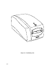
Figure 1-1.
SECTION 1. FEATURES AND SPECIFICATIONS The IntelliStripe® 380, Desktop Motorized Reader-Encoder reads and encodes magnetic-stripe cards and smartcards. CONFIGURATIONS Part numbers and descriptions for the basic configuration are as follows: 16050408 IntelliStripe 380 16050410 IntelliStripe 380, Magstripe Only 16051417 I/O Cable, 10-pin RJ45 connector connects to host 9-pin connector with 12V/Ground connector for Power Supply.
IntelliStripe 380 APPLICABLE DOCUMENTS Standards ISO 7811-2, -3, -4, -5 ISO 7810 ISO 7816 EMV 1996 EMV 2000 Identification cards tracks 1-3 Physical specifications Smartcard specifications Europay-Mastercard-Visa 1996 Level I Specification Europay-Mastercard-Visa 2000 Level I Specification MagTek Documents MCP Serial Transport Protocol, P/N 99875163 IntelliStripe 380, Command Reference Manual, P/N 99875217 SOFTWARE ACCESSORIES The following Software Modules may be required and will assist in the developm
Section 1. Features and Specifications Motorized Card Transport The Card Transport is based on an existing MagTek magstripe/encode module. This module incorporates the following features: Lead-in Roller System The primary purpose of the Lead-in Roller System is to grab the card from the user during card insertion and to make sure the card is mechanically under motor control before reaching the read/write head and its associated drive rollers.
IntelliStripe 380 Spring-Loaded Card Registration Guide(s) The spring-loaded guide ensures that the reference edge of the card is mechanically referenced to the magnetic read/write head, so that the magnetically encoded track data is physically located on the magstripe in accordance with the specifications of ISO 7811. Ability To Transport 0.010 ”to 0.035” Cards Cards that meet the ISO 7810 card thickness of 0.027” to 0.033 will work properly with both magnetic and smartcard elements of this system.
Section 1. Features and Specifications Direction of Magnetic Read: The ISO 7810 and 7811 specifications allow for bidirectional magnetic reading of the card. As such, the Reader provides services that allow the card to be read in either direction. Read Formats: In addition to reading cards that meet the ISO 7810 and 7811 specifications, the Reader reads AAMVA drivers license cards.
IntelliStripe 380 Cable Management The following provisions are made for communication and power lines: • • • • • • Polarization and locking of cable connectors Strain relief of cables Wire routing functionality RJ series connectors for main and auxiliary RS-232 interfaces.
Section 1. Features and Specifications RAM Space: 40 K bytes ROM Space: ROM Flash: Main Program Memory: 512 K Bytes Boot Loader Memory: 24 K Bytes Configuration Memory: 8 K Bytes Host Serial Port The RS-232 Host Serial Port provides serial communications between the Reader/Encoder and the Host Computer. In addition, the Host Serial Port carries DC power from the remote power pack to the Reader/Encoder. The Host Serial Port is capable of communication speeds of up to 115 K bits/sec. USB Port The Host USB 1.
IntelliStripe 380 Opto-Sensor Inputs The Main PCB provides inputs for the three opto-sensors (Front, Encode, and Rear). Rotary Pulse Generator The Main PCB provides input for the MagTek 75/210 bpi Rotary Pulse Generator (RPG). External SAM Ranch Interface, Optional The Main PCB provides resources for interconnect, securement, and power of an optional SAM Ranch PCB. The optional SAM Ranch PCB is accessed from the hatch door at the bottom of the Encoder/Reader.
Section 1. Features and Specifications External Auto-Ranging Power Pack The Reader/Encoder is powered from an external power-pack, which is located near the Host Computer System. Power is routed to the Reader/Encoder through the Host RS-232 cable. Auto-Ranging Input The external power pack features an Auto-ranging AC input that allows for direct connection to either a 100 VAC or 220 VAC, 50 to 60 Hz. Output Rating The power pack is rated at approximately +12 VDC @ 4 A ± 5%.
IntelliStripe 380 SPECIFICATIONS The Specifications are listed in Table 1-1. Table 1.1.
SECTION 2. INSTALLATION The installation of the IntelliStripe 380 Reader-Encoder consists of mounting the unit on a flat surface, connecting the I/O RS-232 cable to the host serial port, the Auxiliary cable to a peripheral device, and the Power Supply to the I/O cable and to a wall receptacle. MOUNTING The bottom of the unit is shown in Figure 2-1 and 2-2. The IntelliStripe 380 may be mounted in one of three ways: 1) foot pads, 2) set of mounting holes for 3 screws (4 x 40), and 3) 4 lock-inplace slots.
IntelliStripe 380 1.105 5.789 Mounting Screws #4-40 (3) 3.230 1.616 .546 Foot Pads (4) Figure 2-1. Dimensions for Mounting Holes for 3-Screw Set and Foot Pads 4.330 1.147 2.810 .959 .375 (4) 2.032 Ø .125 Mounting Flange (1) (use with Lock-In-Place mounting holes) .180 (4) Lock-In-Place Slots (4) Figure 2-2.
Section 2. Installation . Guide Slots & Attachment Holes Card Ejector Rod Card Ejector Rod Mounting Flange Rear Panel Figure 2-3. Rear Panel and Cover Connect the Host PC cable (P/N 16051417) to the RS-232 connector on the IntelliStripe 380 as shown in Figure 2-4 for the RS-232 connection. Connect the Host PC Cable to the PC. Connect the Power Supply Cord (part of P/N 64300091) to the Host PC cable. Connect the North American 100-240v power cord (P/N 71100001) to the power supply.
IntelliStripe 380 To PC Power Supply (with cable) P/N 64300091 Cable P/N 16051417 North American 110V Power Cord P/N 71100001 Figure 2-4. Cable Connections - RS-232 Table 2-1 lists the pins for the host cable P/N 16051417. Table 2-1. Pin List for IntelliStripe 380 to Host PC Cable P/N 16051417 1 2 3 4 5 6 7 8 9 10 14 10P10C RJ Plug PWR GND +12 TXD CTS SIG GND PWR GND RTS +12 RXD +12 2.
Section 2. Installation Cable connections for the USB are Shown in Figure 2-5, and the pin lists are shown in Table 2-2 and Table 2-3. IntelliStripe 380 Back Panel Pin 5 Pin 1 Pin 4 Pin 10 P1 P2 Pin 1 P4 Pin 1 Cable P/N 16051422 P3 Power Supply (with cable) P/N 64300091 North American 110V Power Cord P/N 71100001 Figure 2-5. Cable Connections - USB Table 2-2.
IntelliStripe 380 Table 2-3. Cable Connections – USB Power P3 – 2.5 mm Power Jack Shell Gnd Center Pin +12 Shell Gnd Center Pin +12 Center Pin +12 Wire Color Drain Wire 26AWG Wire (Black) Braid Shield 26AWG Wire (Brown) 26AWG Wire (Red) P4 – 10P10C RJ Plug 1 PWR GND 2 +12 6 PWR GND 8 +12 10 +12 Check all connectors to ensure they are properly connected. Replace the Rear Panel Cover by inserting the mounting clips into the guide slots and press into the attachment slots as indicated in Figure 2-3.
Section 2. Installation Ejector Rod Hole For Card Removal Rear Panel Cover Power And USB Cable P/N 16051422 Figure 2-7. Rear Panel Cover Replaced – USB Connection Plug in the power supply into a wall receptacle.
IntelliStripe 380 18
SECTION 3. OPERATION AND MAINTENANCE The operation of the unit includes inserting and removing the card. Maintenance includes keeping the unit clean and removing jammed cards from the unit. OPERATION The card is inserted with the magnetic stripe down and to the right as illustrated in Figure 3-1. Perform any tasks on the PC as directed. The LED gives status or direction as defined by the institution. Figure 3-1.
IntelliStripe 380 Shut power off by unplugging the power supply (Figure 2-4), and remove the card with the Rod as follows: 1. Remove the Rear Panel Cover to access the Ejector Rod as indicated in Figure 3-2. Ejector Rod Hole For Card Removal Rear Panel Card Ejector Rod Rear Panel Cover Figure 3-2. Ejector Rod Removal from Storage 2. Look into the Hole for Card Removal in the back of the unit, shown in Figure 3-2, to see the jammed card.
APPENDIX A. DIMENSIONS FOR MOUNTING MOUNTING The bottom of the unit is shown in Figure 2-1 and 2-2. The IntelliStripe 380 may be mounted in one of three ways: 1) foot pads, 2) set of mounting holes for 3 screws (4 x 40), and 3) 4 lock-inplace slots. The mounting dimensions of the 3 screw holes and the 4 lock-in-place slots are shown in Figure A-1. Footpad Mounting The footpads are mounted at the factory if it is the default.
IntelliStripe 380 Figure A-1.
Appendix A. Dimensions for Mounting Figure A-2.
IntelliStripe 380 Figure A-3.
Appendix A. Dimensions for Mounting Figure A-4.
Appendix A.