
Installation Manual


INS_RLXE4GE24MODMS_REV– 1 Jul 2016 PAGE 17
INSTALLATION AND OPERATION MANUAL RLXE4GE24MODMS
TECH SUPPORT: 1.888.678.9427
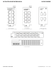
Console Cable
RLXE4GE24MODMS switches can be managed by the console port. The DB-9 to RJ-45 cable
can be found in the package. You can connect them to a PC via a RS-232 cable with DB-9 female
connector and the other end (RJ-45 connector) connects to console port of the switch.
5
9
1
6
1
6
5
9
DB-9 Male DB-9 Female
PC pin out (male) assignment
RS-232 with
DB-9 female connector
DB-9 to RJ-45
Pin #2 RD Pin #2 TD
Pin #2
Pin #3 TD Pin #3 RD
Pin #3
Pin #5 GD Pin #5 GD
Pin #5
Pin Male Connector Female Connector
1 Received Line Signal Detect (Received by DTE
Device)
Received Line Signal Detect (Transmitted from
DCE Device)
2 Received Data (Received by DTE Device) Transmitted Data (Transmitted from DCE Device)
3 Transmitted Data (Transmitted from DTE Device) Received Data (Received by DCE Device)
4 DTE Ready (Transmitted from DTE Device) DTE Ready (Received by DCE Device)
5 Signal Ground Signal Ground
6 DCE Ready (Received by DTE Device) DCE Ready (Transmitted from DCE Device)
7 Request to Send (Transmitted from DTE Device) Clear to Send (Received by DCE Device)
8 Clear to Send (Received by DTE Device) Request to Send (Transmitted from DCE Device)
9 Ring Indicator (Received by DTE Device) Ring Indicator (Transmitted from DCE Device)