
Installation Manual


INS_FVT/FVR20D2I1C4E_REV- 06/22/12 PAGE 9
TECH SUPPORT: 1.888.678.9427
INSTALLATION AND OPERATION MANUAL FVT/FVR20D2I1C4E
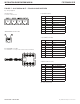
FIGURE 15 – LED INDICATORS
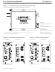
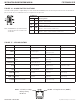
FIGURE 14 – ALARM SWITCH POSITIONS
The mode for alarm operation is configured using a set of two switches labeled ALARM (S2) located on the front panel of the unit. There are two alarm out-
puts on each unit. One on each RJ45 data connector. See Figures 4 & 5 on Pages 3 & 4.
NOTE: The ALARM will also open when Fiber Link
on either SFP port is lost or if Power is lost
on either unit.
GREEN Solid: Link (no activity)
Blinking: Activity
Off: No link
YELLOW Solid: Highest data rate (100Mbs)
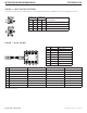
ALARM (S2)
Resulting Mode1 2
ON ON
Alarm 1 – SFP 1 Failure
Alarm 2 – SFP 2 Failure
ON OFF
Alarm 1 – SFP 1 or SFP 2 Failure
Alarm 2 – Video Loss
OFF ON
Alarm 1 – SFP 1 Failure or Video Loss
Alarm 2 – SFP 2 Failure or Video Loss
OFF OFF
Alarm 1 – SFP 1 or SFP 2 Failure or Video Loss
Alarm 2 – SFP 1 or SFP 2 Failure or Video Loss
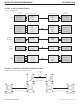
OFF RED GREEN FLASHING
SFP SFP not installed No optical link Link is good and is in use
Link is good but is not in
use
VIDEO – No video signal
An active video
signal is present
–
10/100 LINK – No Ethernet signal Ethernet signal linked –
CONTACT (C)
One or more contacts are
open
Fiber link failed
All four contacts
are closed
–
CONTACT (S) –
Supervised contact alarm
or fiber link failed
No supervised contacts in
alarm state
–
LE-D – Quiet / No Audio Audio Present Call button active
LE-F – Quiet / No Audio Audio Present –
DATA IN Tri-state Low state High state Data activity
DATA OUT Tri-state Low state High state Data activity
POWER Unit powered down – Unit powered up –