
Installation Manual


INS_FVT/FVR20D2I1C4E_REV- 06/22/12 PAGE 8
TECH SUPPORT: 1.888.678.9427
INSTALLATION AND OPERATION MANUAL FVT/FVR20D2I1C4E
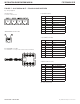
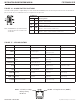
FIGURE 12 – CONTACT SWITCH POSITIONS
The mode for contact closure operation is configured using a set of two switches labeled CONTACT (S1) located on the front panel of the unit. There are four
supervised contacts in the forward (video) direction.
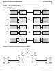
FIGURE 13 – CONTACT CLOSURE SUPERVISED INPUT CIRCUIT
NOTE: These switch settings refer to the trans-
mitter (FVT20D2I1C4E). On the receiver
(FVR20D2I1C4E), S1 SWITCH 1 inverts the
contact outputs. S1 SWITCH 2 is not used.
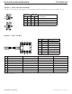
CONTACT (S1)
Resulting Mode1 2
ON ON Full Supervision – When a 1K resistor is connected in series with
the contact closure input, and a 1K resistor is connected in parallel
across the contact closure input. Both open circuits and short
circuits can be detected as well as normal opens and closes.
ON
OFF Series Supervision – When a 1K resister is connected in series with
the contact closure input. In this mode, shorts across the contact
inputs can be detected but open circuits cannot be detected.
OFF ON Parallel Supervision – When a 1K resistor is connected in parallel
across the contact closure input. In this mode, open circuits can be
detected but short circuits cannot be detected.
OFF OFF No Supervision – The contacts will behave as normal contacts with
no Supervision.
INTERNAL
1K
1K
5V
1K Series*
1K
Parallel*
* Optional external resistors
(provided) are required for
supervision. Place close to
the switch for optimal results.