
Installation Manual


INS_FVT/FVR20D2I1C4E_REV- 06/22/12 PAGE 7
TECH SUPPORT: 1.888.678.9427
INSTALLATION AND OPERATION MANUAL FVT/FVR20D2I1C4E
FVT20D2I1C4E
FVT20D2I1C4E
Form ‘C’ Relay
Output
LE-D FVR20D2I1C4E
Door/Barrier
Contact Input
LEF
FVR20D2I1C4E
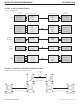
FIGURE 10 – SFP CONNECTIONS
Number of fibers and type of fiber connectors will be determined by selected SFP modules and if point-to-point or redundant modes are required.
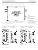
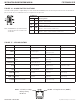
FIGURE 11 – AIPHONE
™
INTERCOM CONNECTIONS
The units are designed to operate with the Aiphone
™
LE-D and LEF intercom system.
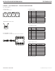
PIN # Wire Color Aiphone Connections
1 Blue LEF ‘E’ TERMINAL
2 Orange LEF ‘1’ TERMINAL
3 Black LEF ‘–’ TERMINAL
4 Red NC
5 Green CONTACT INPUT +
6 Yellow NC
7 Brown GND
8 White GND
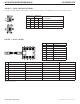
PIN # Wire Color Aiphone Connections
1 Blue LE-D ‘-’ TERMINAL
2 Orange LE-D ‘1’ TERMINAL
3 Black LE-D ‘E’ TERMINAL
4 Red RELAY OUTPUT COM
5 Green RELAY OUTPUT N.C.
6 Yellow RELAY OUTPUT N.O.
7 Brown GND
8 White GND
3 –3E
2 121
1 E
5 54 76
1–