
Installation Manual

INS_FVT/FVR1031_REV–
02/05/10
PAGE 3
INSTALLATION AND OPERATION MANUAL FVT/FVR1031(M)(S)1
TECH SUPPORT: 1.888.678.9427
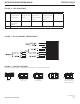
FIGURE 5 – DATA CHANNEL CONNECTIONS
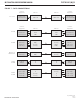
FIGURE 6 – SWITCH POSITIONS
The mode for each data channel is configured using a pair of switches on the front panel of the unit.
Switch
Up-the-Coax
Protocols
RS485
4-Wire Data
RS232 Data RS422, RS485
2-Wire Bi-Phase or
Manchester Data
1 2
1 2
1 2 1 2
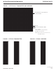
FIGURE 4 – LED INDICATORS
LINK VIDEO DATA IN DATA OUT POWER
GREEN Communication link
has been established
over optical fiber
An active video signal
is present on the BNC
connector.
An active data signal
is present on the
input pins of the data
connector.
An active data signal is
present on the output
pins of the data
connector.
Unit powered up
RED Communication
link has not been
established.
– – – –
OFF Unit powered down.