
Installation Manual


INS_FDX60_REV–
04/23/10
PAGE 6
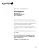
FIGURE 9 – LED INDICATORS
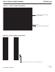
FIGURE 10 – SWITCH POSITIONS
TECH SUPPORT: 1.888.678.9427
INSTALLATION AND OPERATION MANUAL FDX60(M)(S)(-M)
LINK DATA (TX/RX) LOOP BACK (Test Mode) POWER
GREEN Unit In Sync Activity Fiber Link Connections are Correct Unit Powered Up
RED Unit Not In Sync No Acvitiy Fiber Link Issue Exists (Head End) –
OFF No Optical Link – Fiber Link Issue Exists (Far End);
OR Test Mode is Off
Unit Powered Down
Switch
Located on front panel in full
size modules and on back on
small size modules.
The first two switches set the
data type, the third toggles
Loop Back Test Mode.
RS232 Data
1 2 3*
RS422, Bi-Phase or
Manchester Data
1 2 3*
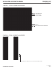
RS485
4-Wire Data
1 2 3*
RS485 2-Wire,
Sensornet Data
1 2 3*
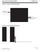
Loop Back
Test
1 2 3*
* Loop Back Test Mode
(see Page 8)