
Installation Manual

INS_CLRFE1EOCX/M-REV- 12/23/14 PAGE 3
INSTALLATION AND OPERATION MANUAL CLRFE1EOC(E,P)/M SERIES
TECH SUPPORT: 1.888.678.9427
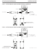
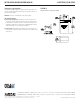
APPLICATION DIAGRAMS
PoE Pass-Through Mode
Non-PoE Mode
IMPORTANT NOTE. PLEASE READ. The applications are shown as general representations only and are not intended to show detailed network topologies. Your actual network will differ,
requiring changes or perhaps additional network equipment to accommodate the systems as illustrated.
Please contact ComNet’s Design Center to discuss your specific requirements.
PoE
Ethernet Switch
or Midspan
Local Remote
CLFE1EOC CLRFE1EOCP/M
PoE Camera
Ethernet
Switch
Local Remote
Power Power Power
CLFE1EOC CLRFE1EOCE/M
IP Camera
Ethernet Connection
PoE Power
Extended Connection
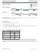
TABLE 1 – APPROXIMATE MAXIMUM EXTENDED DISTANCES
1
Media COAX - RG59/U
Camera Data Rate
10M 100M
Non-PoE Camera
1
5,000 ft
1,524 m
2,000 ft
610 m
PoE CLASS2 Camera (6.5W)
1
3,000 ft
914 m
2,000 ft
610 m
PoE CLASS3 Camera(13W)
1
(10W in Pass-Through mode)
750 ft
228 m
750 ft
228 m
1
Distance figures are based on a 50V PSE PoE power source, and external power supplies for the extenders. Distance figures are obtained using
in-house testing mirroring installations. Factors such as coaxial/copper cable quality, the number of connectors/splices in the cable run, the use
of PoE, and environmental conditions encountered within the installation may affect the actual transmission distance, and should be taken into
consideration. Due to advanced negotiation signaling required in IEEE 802.3at applications, Pass-through applications are limited to IEEE 802.3af PD
devices only.
1 Mixed PoE and Non-PoE systems can be implemented.
2 All Non-PoE systems require local power.
3 PoE powered operation requires that a PoE Camera be connected, and that the camera power requirements are understood.
4 Lower data rates generally provide longer operating distances.
APPLICATION NOTES